Beethoven's 9th

Anyone got a recommendation for a good recording of Beethoven's 9th (or 7th for that matter)?
I've got the Von Karajan version from the early 70's, love the performace but the sound quality is bad - not sure if it was badly recorded, or because it's been 'digitally remastered'..
or maybe I'm reaching the limits of my system.

Sound is cluttered and quite harsh, hard on the ears, particularly at volume (which is the only way to listen to Beethoven)

I only listen to it about once a year when my delusions of grandeur surface... good for drowning out the counry from next door too...😀

Diagnosing a simple transistor guitar amp

I've built a clone of an old Gibson GA-5W transistor guitar amp (schematic attached), because I liked the sound of one that I heard and wanted to understand it better. Simple thing with a common emitter BJT preamp stage, and a push-pull power stage that I don't 100% understand yet.

It passes signal, but the sound is fuzzy and distorted, at all volume levels. I've checked a bunch of connections and component values, and tested it against the voltages given on the schematic, and everything looks about right. I've also poked around with my scope and a signal generator: if I isolate the first stage, its output looks great, no problems there. At the speaker connection, the signal is asymmetrically distorted, and looks pretty similar regardless of signal volume. It doesn't look like crossover distortion to me, and doesn't respond much to changing the bias trimpot.

So, something going wrong after Q1. I tried looking at the signal at a few other points, but I don't really understand what I'm seeing:

- When I connect the first stage to Q2, the signal on the base of Q2 looks very distorted — I guess I'd describe it as extremely clipped on the bottom of the waveform. It looks significantly worse than the output signal at the speaker!

- At the collector of Q2 / base of Q3, I can barely see the signal because there's a pretty loud sawtooth at about 2khz.

- At the base of Q4, I see something that looks similar to the base of Q2, but with a lot of high frequency noise right where the wave is most distorted.

I'm a little bit stumped. My usual approach would be to isolate sections of the circuit, but Q2-5 all kind of work together. I also don't really understand how Q2 and Q3 are working here. I'd appreciate any advice or suggestions.

860934d1594837840-diagnosing-simple-transistor-guitar-amp-ga5w-pdf

View attachment GA5W.PDF

Choices for 2 way build using existing design

I'm interested in doing another two way build of an existing design. Either stand mount or small floor stander and just need a little nudge in the right direction to make the decision as there are many options out there. I listen to a mixture of genres predominantly via digital streaming source but still have CD and Vinyl. I particularly enjoy designs that resolve vocals and mid range well with detail but not over analytical. I like a good amount of bass but detailed.

My listening space is approximately 12ft (3.6m) x 16ft (4.9m) with the speakers positioned on the longest wall and listening position opposite and roughly 3ft (1m) high.

I've had speakers with a mixture of designs, metal cones, coated paper cones (I do like) and I've had soft domes and planar tweeters - but I'm not so much bothered by the ingredients as the cake. I've shortlisted some designs but what gives me pause is that many are designed for free space and having them near (but not up to) a back wall can change the signature of the sound. I also usually angle my small floor standing speakers back by about 6-8 degrees to get the drivers to point to ear level.

So with this said the criteria is:

Design:
2 way ported
6" or 7" mid bass
Small floor stander or large stand mount - max overall height 70cm (27in)
15 litres - 17 litres

Position
Close to wall 30cm - 45cm (12in - 18in) - to front of speaker

Sound profile
Excellent midrange
Wide sound stage and separation of instruments
Good detailed punchy bass (within the limits of the design size)
Detailed and nuanced but not overly analytical
Non fatiguing to listen to

Budget
£350 ($450) - £500 ($650) for drivers and crossovers

Shortlist of kits/designs
Paul Carmody Amiga
Jeff Bagby Mandolin
Jeff Bagby Adelphos
John Krute SR71
Ampslab Starling TA
Madisound Seas CA18RNX

Smaller alternates
Paul Carmody Carrera

Attachments

  • listening.jpg
    listening.jpg
    91.5 KB · Views: 338

Phoenix Gold EQ232 rca output

Si I bought this eq not paying close enough attention to the output rca's and I was hoping Perry or anyone else would know where I can buy the ground case/cover for the rca's. I have had a hifonics unit do the same thing where to tight of an rca pulled those ground pieces off. I tried to searching for it but cant find them.

Only thing I can think of was order a set of these PJRAN1X1U01AUX Switchcraft | Mouser

In hopes that I can harvest those outside canister and use it to fix this:

Attachments

  • 20200809_164754.jpg
    20200809_164754.jpg
    950 KB · Views: 85

The CBT Catch-22

CBT speakers are interesting, and I like how they sound. I've heard them a few times. An issue that they have, is that it's hard to get any kind of 'sparkle' from them.

zaz2e6X.png


Here's an unprocessed response measurement from a CBT owner on Reddit.

ax8vPur.png


Here's the processed response. Note that the high frequencies droop by about 10dB. That's why it's hard to get that 'sparkle' with a CBT. Like all arrays, you get tremendous efficiency when the elements are close enough to sum constructively, but at high frequency they interfere with each other.

hNjQSC6.jpg


Here's their speakers.

They wrote:

"I've never subscribed to the idea of full range speakers for anything but Jazz and I'm afraid that CBTs turned out to be no exception. I really was hoping they would be though. The CBT24 effectively sacrifices the treble performance for the CBT midrange. On one hand, the use of the Dayton 2.5" drivers made them more affordable than any other CBT but at the cost of performance. I'm convinced that CBT is a good technology for loudspeakers, but I would reserve it for 2-way designs where cost is not a design decision.

For $1500 it's not hard to find a traditional dynamic loudspeaker that can deliver a flat on-axis response with decent off-axis. For music, KEF LS50 and Ascend Sierra-2 are simply a far more resolving speaker than the CBT24."

WTB WHAMMY, DAC

Primarily looking for a used WHAMMY (with socketed opamps) at a reasonable price. I have extra Burson Classic opamps on hand on account of not liking the Akitika headphone amp at all, so if you have some other use for the opamps in the WHAMMY you are free to keep them.

I was planning on picking up a Gustard A22 DAC when I get paid in a few weeks, but if anyone has a decent DAC they're looking to sell at a reasonable price, I could be persuaded to buy that instead. 🙂

Adcom GFA-555 II with a bad channel

Hello,

I know there are several threads here on this amp but many started ten or more years ago. A clean start seemed appropriate. However, I have read through most of them in large part. I picked up an Adcom GFA-555 II at GW yesterday. The guy there said it powered up fine with no pops or hums. Hmmmmmmm...... It had 149.99 on it. I took it to the test station and indeed the power light came on but so did the thermal protection. I pointed that out and offered them fifty bucks. Worth a shot I thought.

I got home and turned it on. I took readings on the dc offset at the speaker terminals and forgot to write them down but the left channel was fine but the right was high (IIRC). Opened her up and did a visual inspection and it is really clean inside. I noticed that the thermal protection no longer turned on so I put a pair of cheapo 8 ohm speakers on and a FiiO player with line level output control. I got good clean audio from the left channel and nothing from the right.

Checked the fuses next (probably should have at first) and the negative side of the right channel 7a fuse was melted but not blown. All other fuses were fine. Went to a local electronics store got a new fuse and put it in and started it up slowly with my variac and it immediately started chugging and humming so I shut it down.

I have a variac, a good DMM and a borrowed O-Scope that I do not know how to use. I have figured out how to dismantle it to get to the power transistors.

I have seen where some folks do an in-circuit test on the transistors but do not believe it to be very reliable. Is there a good way that will at least get me started on locating the fault? I have also read that usually it is one transistor that goes but have to believe that the rest that did not fully go have been damaged. At least I have one functioning channel.

I am studying the service manual and doing an eyeball trace following wires and circuits to get a sense of where things are. Interestingly, the big caps look new and are 125 v vs. 100v. And, the power TO-3 transistors are mounted on silicon/plastic thin wafer but I cannot see any thermal paste at all. Is that normal?

Last thing I fixed (with a lot of help here) was an old Nikko NA-850 and the culprits were little transistors that were hidden under wires. The symptoms there were similar to this amp.

I am willing to take out each transistor and cap and test out of circuit if needed. I learned last time that powering up too soon just blows what you just put in. I want to understand where the fault is before I replace anything.

All I hope to get at this point is a starting point. Thanks James

Why do headphones seem to measure so poorly?

I know everyone says that headphones sound better than speakers and are more accurate, and I feel like I agree with stuff under $100. But, I just don't see that with mid level headphones or slightly higher end stuff? Btw, just putting it out there, I haven't listened to any truly high end headphones. Maybe my ears are broken or something, idk, but for example, I have a pair of definitive technology computer speakers that I got for $199, and they sound better to me than my friend's Audio Technica m50x's. I can hear more detail in my speakers, and it sounds cleaner I guess? Now I know sound quality is subjective, but my speakers just sound flatter than her m50x's except for the bass on these speakers which is slightly boosted. I looked up the frequency response of the m50s here: Headphones - 1.4 - Graph - RTINGS.com

I'm not sure how accurate those measurements are, but I'm not surprised, that's what it sounded like to me. Those measurements don't look flat compared to my Definitives which looked a lot more flat to me when I measured them. And I'm sure there are flatter bookshelf speakers than my definitives given the price point. So what gives? Why do people say headphones are much more accurate than equivalent speakers? Like I said, maybe there's something wrong with me XD but can someone clear up my confusion?

Passive attenuator - balancing amp - Icepower

Hi all - Is it OK and/or sensible to go from a single ended input to a 50k pot, then through a balancing stage and then into an Icepower 300as1 balanced input?
I can power the DRV134 balancing circuit directly from the ice power modules so it makes for a very simple single input high powered amp with volume control.
Is the balancing stage necessary? From what I have read these modules sound better with a balanced input.
Any and all suggestions and opinions very welcome!

ShibaSoku AM70A service manual needed / problems

Picked up a ShibaSoku AM70A 2CH Audio Analyzer for a good price (I thought). It powers on and the oscillator works (verified signal on scope) but when I route it's output to it's input (either channel) it doesn't read anything. There is also no signal from the monitor output.
Tried searching for service manual and operator's manual but haven't turned up anything yet.
Unit seems like a nice piece of equipment if I can get it back to working condition.
Opened it up and took out all the boards and did a visual inspection. Nothing obvious found. Probed around on power supply voltages that I could see/reach and nothing seems out of the ordinary.
Anyone have any ideas where to start?

Fake BD139/140 ?

I was given a lot of BD139/140

Transistors have no metallic plate like TO126, all sides are isolated. The thickness is 3.3 vs 2.6mm. Caracteristics (vbr, hfe) are just above datasheet listing.

I already saw this isolated package but I didn't found any reference of this in fairchild datasheet for 139/140.

fake or not ?

Attachments

  • BD139FRONT.jpg
    BD139FRONT.jpg
    390.1 KB · Views: 498
  • BD139BACK.jpg
    BD139BACK.jpg
    393.8 KB · Views: 431
  • BD139MARKING.jpg
    BD139MARKING.jpg
    168.5 KB · Views: 457

FS: Set of 10 Classic Vacuum Tube Design Books

SOLD: Set of 10 Classic Vacuum Tube Design Books

Link to Photo of books

The following classic books (from 1937 to 1999) are AVAILABLE AS A SET ONLY. Please don’t email asking if I’ll sell just a specific book.

To get an idea of what these are worth, I just ran the titles through Amazon (this was a year or so ago). Holy jumping horntoads Batman, if you were to pay top dollar for each of these on Amazon, this is over $3000 worth of books! But I know you’re a bargain shopper, so you’ll take the absolute best price on each - that’s still almost $350 before shipping!

They’re all in good to very good shape. Often they have the original owner’s name written inside the cover, but otherwise pages aren’t torn, marked or defaced.

I’ll take $100 for the lot plus shipping and PayPal, price is FIRM. Shipping will be a bit, but I'll ship USPS book rate. The first book alone sells for more than that on Amazon.

Thanks for your interest!
Frank

Audio Reality
Bruce Rozenblit
1999
Amazon: $128.98 - $755.68

Electronic Analog and Hybrid Computers
Korn & Korn
1964
Amazon: $21.99 - $220.31

Fundamentals of Vacuum Tubes
Eastman
1937, 1941
Amazon: $11.31 - $289.44

The Radio Amateur’s Handbook
American Radio Relay League
1967
Amazon: $2.50 - $199.99 (only 1967 was $50.00)

Radiotron Designer’s Handbook, Fourth Edition
Lanford-Smith
1954
Amazon: $15.00 - $194.79

Receiving Tube Manual RC-30
RCA
1975
Amazon: $16.95 - $44.99

Tube Circuits for Audio Amplifiers
Mullard Ltd.
1959 (reprinted 1993)
Amazon: $13.64 - $623.89

Vacuum Tube Amplifiers
Valley and Wallman
1948 (reprint, 1965)
Amazon: $68.15 - $378.59

Vacuum Tube Circuits for the Electronic Experimenter
Julian M. Sienkiewicz
1961
Amazon: $54.90 - $75.05

Vacuum-tube and Semiconductor Electronics
Jacob Millman
1958
Amazon: $9.95 - $248.56

Some questions on open baffle speakers

I am interested in getting a good hi-if setup. I am looking for a very realistic soundstage with a rather flat frequency response. The music I would be listening to would be centred around piano solo and orchestral work.

Looking into this, I found out about open baffle speakers and they seem like this would be the best route to go. The room that I would be using these in is quite large with many diffusers on the walls and ceiling.

However, I want to build my own and as this is my first attempt at hifi diy (normally do musical instrument diy), I am at a bit of a loss of where to start.

What are the most popular/respected diy designs, and what differentiates them? I have read about the LX521.4, but I have absolutely no idea why it needs such strange type of amplification? I ideally wanted to use a tube amp, like a leak stereo 20 or similar.

When looking into designs, I found that to get good bass response, a high Q woofer is needed, but this can be quite undefined compared to a low Q woofer.

I am after a very detailed and defined sound with convincing 3D soundstage.

I am obviously not adept enough to design my own, so I am generally asking for some guidance on which already proven diy designs are out there, and what books/resources would be good for me to read to get a better understanding of this area.

22uf

Woofer Eton 7-612/C8 - what do you think?

hi all,

what do you think of this woofer / mid

MONACOR: 7-612/C8/32RP from Eton, c ' is the Orchestra series.

This is for use in a small 3-way, so it's the bass performance that I'm interested in. According to the waterfall measurements that I consulted in a German magazine, there is a little drag at the bottom of 200hz, otherwise up to 800hz is quite clean ... does anyone know this woofer?

Thank you in advance for your comments!!

Denis

2 Way speaker project review

Dear Experts,

I'm building a budget 2 way speaker and I would have your opinion on where I am and if my crossover design is correct. I've simulated and built the cabinet, vented box, braced, measured with the UMIK-1 at 1 mt
Drivers: Tymphany XT25TG30-04 with horn, SB SB20PFCR30-4
Picture1.jpg
FR, in box at 1 mt, gated, not smoothed
picture 2.png
woofer
picture 3.png
tweeter
picture 4.png
FR simulated with BoxSim
picture 5.png
Crossover network

My questions
1. is the XO design correct, elegant, or can I make something better?
2. the impedance goes below 4 in some frequencies: I use a standard AV amplifier, do I need to correct them or not (I will use the speakers at loud volume)
3. the drivers are acoustically misaligned by 7mm: do I need to correct it?
4. Is the frequency response good, and how much I can trust BoxSim to buy expensive crossover parts?

Thanks to all for the inputs!!!

Cheers

ES9018 I2C simple volume control

It's based on PIC16LF84A and uses rotary encoder to set volume. There is no visual indication of volume level, except PWM signal at RB2. You can attach an analog voltmeter there. Volume level is stored in internal EEPROM at power shutdown. PNP transistor, 3k3, 18k, 39k circuit senses Vdd drop and set RA1 input low, then 470uF capacitor keeps Vdd long enough for the program to store current volume level in EEPROM. LED connected to RB3 goes on after succesfull initial startup write to DAC. Power supplies for DAC and volume controler should start at the same time in order to avoid audible pop when DAC starts first, or maxed volume level when DAC starts after the controller sends initial volume level. Attached schematics, basic program listing, and compiled hex file.

Attachments

Bias Circuit Design Questions

I'm working on designing a class B amp from scratch based on the typical three stage design. The output is Darlington with 2-3 pairs of output transistors. I'm going for around 100W into 8 ohms.

The best explanation of bias circuit design I've found is from Bob Cordell's book, where he explains Vbe multipliers. I'm working it out in SPICE but when the tempco is correct the outputs have impossibly high bias current.

So my question is: how to set the overall quiescent current level separately from adjusting the tempco? Most circuits I've seen just have a pot in the lower half of the voltage divider around the bias transistor. Adjusting this would just change the multiplication factor, but I would prefer to have a fixed tempco and then adjust the offset to set the quiescent current in the outputs instead.

Can someone explain the reason behind this (very common) approach and how best to set the overall bias current while also having the correct tempco?

Damn it - I've got the bug - How to upgrade my CA A1 MK3 (NON SE)

Hello All,

Right, after looking at cheap ebay $20 "amps" I decided to buy a faulty CA MK3 non SE for the same price and fix it. Replaced caps and the volume pot and now it sounds golden! you would think job done... but:

Having tinkered with it, I am thinking that the case actually is very open for modifications... maybe I may want to replace the transformer and replace the PCB entirely! to provide more watts as 25W is a bit low. or possibly a transplant from a faulty Topaz or similar CA amp, they look quite similar. what do you guys think? waste of money or potential to diy my own amp?

also first post, so be gentle.

Thanks!

16LS, CXPP25-8K, THD&Freq plots. Bias adjustment and questions.

This is the S-5 k-16LS kit amplifier with CXPP25-8K output transformers. It's a PPP design and I wish I had transformers that had 4 ohm taps. I previously looked at rebuilding it as a 3 pair output to lower output impedance. Edcor says 120mA max AC+DC , but never specified on B+ or per plate lead. Others have asked and not gotten answers. I decided that 120mA on the B+ was unlikely since Hammond rates per plate lead and you'd need pretty high volts to get 25W with 120mA total.

I decided to do some testing. There is currently 100mA total on the B+, so 25mA a tube. Changing the cathode bias resistor experimentally I increased it to 163mA and distortion went down. So I figure that the core isn't saturating, and probably won't melt the winding. Transformers never warmed up before.

Here is the test data for this amp since I've never seen the data before. Of course the output transformers are upgraded, and no measurements were needed to know the Edcor was better in the bass frequencies. It's wired in UL mode. I was told that 20% UL taps would be better than the 40% with these tubes, but I have(kinda like I have 4 ohm speakers) 40% taps. This lowers output impedance, right?

I'll try to post test data with old transformers, and the Edcor without UL later.

Frequency response at default .1Vrms output. There is a decimal point in the db number 😉
attachment.php


Frequency response at approximately 4 watts, but I'm not sure if this "level" is in or out now.
attachment.php


1 Watt into 8 Ohms 100mA
attachment.php


4 Watts into 8 Ohms 100mA
attachment.php


1 Watt into 4 Ohms 100mA
attachment.php


4 Watts into 4 Ohms 100mA
attachment.php


1 Watt into 4 Ohms 163mA
attachment.php


4 Watts into 4 Ohms 163mA
attachment.php


Schematic
attachment.php

Attachments

  • Responce.1Vrms.png
    Responce.1Vrms.png
    16.3 KB · Views: 340
  • Responce4Vrms.png
    Responce4Vrms.png
    23.1 KB · Views: 312
  • 1W8OHM100mA.png
    1W8OHM100mA.png
    19.2 KB · Views: 348
  • 4W8OHM100mA.png
    4W8OHM100mA.png
    18.8 KB · Views: 322
  • 1W4OHM100mA.png
    1W4OHM100mA.png
    19 KB · Views: 323
  • 4W4OHM100mA.png
    4W4OHM100mA.png
    19.1 KB · Views: 314
  • 1W4OHM163mA.png
    1W4OHM163mA.png
    18.9 KB · Views: 63
  • 4W4OHM163mA.png
    4W4OHM163mA.png
    19.1 KB · Views: 326
  • k-16ls - schematic.jpg
    k-16ls - schematic.jpg
    89.3 KB · Views: 397

Scanspeak 23W/4557T02 Revelator open circuit VC

I took a punt on the above driver as it was pretty cheap despite being faulty. The seller mentioned it was intermittently working and on arrival I managed a DC voice coil measurement but indeed the DMM started to show the open circuit.

Anyone any experience of these things? I showed it to a sound engineer and he said he'd first try the connextion between tinsel lead and the enamelled wire where it glues to the underside of the cone. This seemed to make sense and is an easy enough thing to try.

Would be good to get this working as it models very low in small boxes.

Thanks

FS: Sennheiser HD650 headphones.

SOLD -Sennheiser HD650 headphones.

Thought to try here before ebay.

One pair of HD650's in excellent condition and working order no issues. No original box unfortunately but will be packed extremely well.

Only selling as I will put the funds towards some Focals.

SOLD

Attachments

  • IMG_1879.jpg
    IMG_1879.jpg
    110.5 KB · Views: 586
  • IMG_1882.jpg
    IMG_1882.jpg
    113.6 KB · Views: 594
  • IMG_1883.jpg
    IMG_1883.jpg
    179.6 KB · Views: 588

Help me improve the response of this crossover (Stock from a Elta stereo CD player)

I found this simple crossover (i really dont know if its crossing over) with just a capacitor of 4.7uf b/w the tweeter and the mid driver. The response of the system is very flat now, i would like to get in a bit more punch to the lows and the highs. Opened it up while trying to add a Bluetooth module to the system and found the crossover setting.

Attached is the image of the 2 way system.

Attachments

  • IMG_0005.jpg
    IMG_0005.jpg
    583.1 KB · Views: 135

Micro Seiki CD-M2 CDM2 CDM-2 - test reports wanted

Who have heard this compact disc player?

‚b‚c-‚l‚Q (http_k-nisi.hp.infoseek.co.jp/cd-m2.htm]‚b‚c-‚l‚Q)
MICRO CDƒvƒŒƒCƒ„�[CD-M2‚ÌŽd—l ƒ}ƒCƒNƒ�
(http_audio-heritage.jp/MICRO/player/cd-m2.html]MICRO CDƒvƒŒƒCƒ„�[CD-M2‚ÌŽd—l ƒ}ƒCƒNƒ�)
Ebay Item number:190401700568 Micro CD-M2

At first look it seems to be similar to the Philips CD-960 (CD960) and Marantz CD-94 (CD94)

philips high end cd player CD-960

http://www.diyaudio.com/forums/digital-source/89200-help-philips-cd960.html#post2226966

Attachments

  • MICRO_CD-M2.gif
    MICRO_CD-M2.gif
    160.3 KB · Views: 945
  • Micro CD-M2 rear.pdf
    Micro CD-M2 rear.pdf
    59.5 KB · Views: 389
  • micro CD-M2 open.jpg
    micro CD-M2 open.jpg
    883.1 KB · Views: 968
  • micro CD-M2 open-II.jpg
    micro CD-M2 open-II.jpg
    545.4 KB · Views: 1,237

Odd Volume Control Issue

I have an strange issue that just appeared on my Rotel RA-2030.

The volume control has just developed a flat spot between about 40 and 50%. There is absolutely no static or other issues, the volume just stops increasing in this range and both channels are affected equally.

I’ve cleaned and metered the pot and the resistance is linear all the way through a full sweep.

Next step will obviously be start pulling and testing components but I’ve never heard of this before and wondered if anyone else had.

Kef Constructor series CS1 Vancouver speakerlab build - info sought

i all , I just acquired a set of Kef CS1 speakers locally. The previous owner says he purchased them from Speaker Labs (?) on West 4th in Vancouver in the 90's - Very well built as you can see from photo. Interestingly they are set up for bi-wire on the back. The p.o. indicated that the crossovers had been "tweaked" by an engineer from UBC but could't remember much more.
So, I am seeking out info. on these or similar models. .. and yes I know this would be helped by removing the drivers etc. but I am not particularity skilled at that ( i.e. a klutz) and thought I would try the non-invasive approach first . Thanks in advance.

"Be kind, be calm and be safe" Dr . Bonnie Henry.

Attachments

  • kef.jpg
    kef.jpg
    674.9 KB · Views: 497

After 10 Years with my Shoog EL34s>>>>

After over 10 years with my Shoog EL34 triode / antitriode amp on 300W toroids and a lot of travelling around, time to use my bigger bottles (813s) that I have had for more than 20 years as SE with parafeed Toroids before I pop my clogs, especially as I have the bases, top caps and PSU Iron.
I want to use mosfets as the valve loads but am not into sand. HT around 1.2KV. Any ideas for these loads, I remember seeing something using about 600V HT a few years back maybe modifiable to higher voltages with more advanced components today. Not looking for lots of power 10W of "Good" sound would be fine. This will be for a winter project, Covid permitting.

Nostalgic rebuild plan - would love your input

Hi all! Haven't really been around in a while, but I'm getting back into hifi and I have a project I'm wanting to tackle and I'd love some input.


So I'm thinking about embarking on a labor of love to restore some speakers my dad gave me when I was 13 or 14. He bought these new, I'm assuming from Radio Shack circa 1978-1980, because he bought a Realistic receiver and turntable at the same time. They are a private label brand called Ultralinear and are basically a knock-off/clone of a JBL L100. They're not expensive speakers and don't sound fantastic, not then, not now, but I don't really care as they remind me of my dad. They're classic rock blasters.


The attached link is NOT of my actual speakers, just the same model.


Ultralinear 210w/o speakers (rare west coast style classics!) Saanich, Victoria


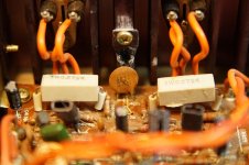
I replaced the rotted out drivers in 1994 or so with some no-name 12's I got from JC Whitney. They've been stored in my garage since the early 2000's and I think I can bring them back to life. I found another article online where a guy restored a set like these, but he just recapped the crossover.


Advice on fixing up Ultralinear speakers — Polk Audio


I'm planning on a little bit more, replacing all the drivers with some low-cost but quality components from Parts Express. Tell me what you think and if you've ever done this (or worked with these speakers before!) BTW, these are not my main speakers, I have a nice set of 1st generation early 80's Klipsch Heresys with a sub for that.


Specs:


Ultralinear 210 W/O speaker
Frequency response - 29 Hz to 21 kHz
Power - Min 10W RMS - Max 50W RMS (circuit breaker)
Nominal impedance - 8 ohms
System components:
12" foam-edge air-suspension low frequency driver
5" self-enclosed edge-treated mid-range transducer
1" ultra-wide dispersion soft dome high-frequency radiator
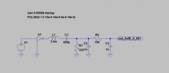
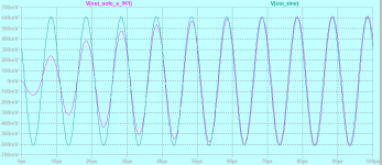
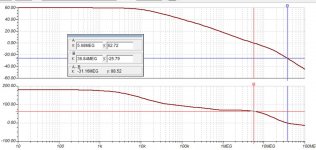
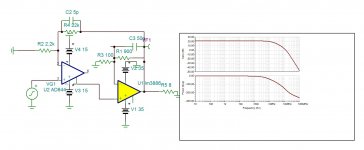
Crossover frequencies: 1400 Hz and 5000 Hz with front-mounted high frequency level control


Replacement parts:


New caps: Dayton Audio DMPC-30 30uF 250V Polypropylene Cap x 4 (5% MP), Dayton Audio DMPC-12 12uF 250V Polypropylene Cap x 2 (5% MP)


New tweeters: Dayton Audio DC25T-8 1" Titanium Dome Tweeter (x2), 8 ohms, 50 watts, 3 kHz - 20 kHz, 93 dB 1W/1m


New mid-range: Pyle PDMR5 5" Sealed Back Mid-range Speaker Driver (x2), 8 ohms, 100 watts, 450 Hz - 7 kHz, 92 dB 1W/1m


New low-frequency: Dayton Audio DC300-8 12" Classic Woofer (x2), 8 ohms, 80 watts, 25 Hz - 2,500 Hz, 90.3 dB 2.83V/1m

Zapco Z-2KD Amplifier

Received amp with blown power supply and outputs rebuilt PS board and tested without outputs and rail voltage was 70 volts. Rebuilt output board and amp draws excessive current and rail voltage is only 20 volts. High side and low side outputs are receiving gate signals but there is no rail to rail oscillation. It shows a small oscillation on scope then stops.

NAD Wireless USB DAC 1 & Pioneer AS-WL300 NIB

FS: NAD Wireless USB DAC 1 & Pioneer AS-WL300 NIB (Lower price)

NAD wireless USB DAC 1, used but in very good condition.
All accessories included. Shallow scratch on the righthand side of the top - see photo.
Universal powersupply with plugs for all countries. Wanted: $70

Pioneer AS-WL300, AV Streamer. New, in sealed box.
I don't know how the power adaptor looks like, what type plug it has and what voltages.
Bought in EU. Wanted: $60


Shipping worldwide is $19.

Let me know if you want to trade.

Attachments

  • NAD-11.jpg
    NAD-11.jpg
    90.6 KB · Views: 122
  • NAD-2.jpg
    NAD-2.jpg
    139.5 KB · Views: 125
  • NAD-3.jpg
    NAD-3.jpg
    151 KB · Views: 118
  • AS-WL300-1.jpg
    AS-WL300-1.jpg
    153.8 KB · Views: 127
  • AS-WL300-2.jpg
    AS-WL300-2.jpg
    178 KB · Views: 135
  • AS-WL300-3.jpg
    AS-WL300-3.jpg
    144.6 KB · Views: 66

F0D2741A Opto-Iso for Motu 896 Mk III

I've looked for a replacement part F0D2741A in the power supply of a MOTU 896 Mk III, but none of my suppliers have it. Even though this is only 9 years old, all indications are the part is obsolete, no longer available.

I've recapped the dead power supply and also replaced the FSCM0765R power IC, checked the diodes and replaced all electrolytic caps. The power supply will not start. Even if disconnecting the load.

About all that's left is the opto isolator chip, but Mouser, etc., doesn't understand this part number.

Any modern substitutes that work in place of this?

WinISD pro signal question

WinISD pro signal and cone excursion question

Hello, could someone please explain - what is WinISD signal in regards to cone excursion?

When I simulate Signal on cone excursion window, and that reaches its maximum - Is the signal rated as RMS, Program or Peak? If its RMS then I should not worry about over excursion, but is its peak then I would have to divide this by 2 to get a program rating and another 2 to get to RMS rating for calculating limiter settings.


for example
Vf0JwI1.png

RMS, Program or Peak?

The most advanced GainClone amp yet

It seems like more serious players are entering chip amps field now: http://www.6moons.com/industryfeatures/gill/gill.html

To keep up with the Joneses, I designed an integrated amp that pushes the envelope even further.

Starting with custom made toroids that have special windings and amorphous cores and dual mono design to the bridged amps output and TVC integrated volume control.

From the outside, the chassis is stylized by Levinson reference DAC and transport.

Attachments

  • 1.jpg
    1.jpg
    77.7 KB · Views: 21,314

Improving the NAD 306 amp. What to replace ??

Hi again .
I inspected every cap inside NAD 306 amp and also the service manual .
In the main amp section all electrolytics are polar ones .
I was expecting to find some non-polar electrolytics to replace those with film caps but I can't find any of those .
I added a photo with the scheme .
Maybe this amp have some huge compromises ?.
And maybe the signal is passing thru some polar electrolytics and those can be changed with non-polar ones ?
What needs to be replaced ?
How can I improve this amp ?
Regards

Attachments

  • Untitled.jpg
    Untitled.jpg
    620.4 KB · Views: 665

Mercury Arc Rectifier with Cold Cathode - Test Setup

hi!

Here is a short video about the test setup of a cold cathode mercury arc rectifier, just to produce some nice discharges 🙂

Cold Cathode Mercury Vapour Rectifier Tube - Test Setup - YouTube


An AEG J10/1000/1Gl rectifier tube with a cold mercury cathode.
There is a liquid cathode pool on the bottom which consists of a huge amount mercury.

Into this mercury pool, there produdes an ignition electrode (made out of graphite I guess, possibly with a coating).

The Anode consists of a big hollow cylinder, out of graphite as well.

When a sufficiently large ignition pulse arrives, the mercury atmosphere gets ionized and the entire path between cathode and anode begins to conduct with an arc. specs:

- max. blocking voltage, peak value: 15KV

- max. peak current, peak value: 1000A

- max. average current, continuous: 1A

- Application: controlled rectifier for adjustable power, my tubes come from the power supply of a short wave transmitter

- use of a single tube for DC operation, two tubes for AC in inverse-parallel connection

Remote control matrix switch - clueless newbie

Hi everyone, I'm trying to build a thing, but my cluelessness is just raising questions. I will use this thread as a log of my activity, and maybe if anyone can help that would be amazing.

The general idea is a 4 stereo input 8 stereo output remote control (over Arduino with LAN) audio switch and volume control. I have 8 audio zones I wish to switch input to. I drew my general design attached to the thread. I am fine with the Arduino bit.

Constraint: prefer through-hole components. I am fine with getting and assembling SMT things, but these parts are expensive so I want to be able to screw up and not waste money.

Constraint: it just needs to sound "quite good" I am not an audiophile and these are mostly not for music.

The components I have sourced are the MT8816 matrix and the PGA2311 volume control. I'll need 1 matrix and 8 volume control chips. They both come in DIP so that is great.

Now down to the questions/discussions I already have.

1. Power supply. Both the matrix and volume chips require a dual supply +-5v and a digital 5v. I'm a bit confused about the difference between the analog power supply and digital power supply. Will I need two separate AC/DC converters? I have never worked with this before but I see some sources online on how to build these analog supplies. I'd prefer to buy the power supply from somewhere. Online I see something like https://www.renesas.com/eu/en/www/doc/datasheet/icl7660.pdf which can produce the -5v. Could I just use that for -5v and use +5v for the second rail and also the digital 5v?

2. Input / output buffers. The volume chips say they need "For optimal performance, drive the PGA2311 with a low source impedance." I don't really know what that means. Should I have some kind of buffer op-amp on the input before the matrix and also after the matrix before the volume chip?

3. Phono socket shared ground. All the twin phono socket pcb mounts I've found share a ground. e.g. https://www.mouser.co.uk/datasheet/2/670/rcj-22xx-1219155.pdf should I just join my left and right ground for each channel output from the volume chip?

I'll keep posting here, but thanks for any help or just pointers I can get in the meantime.

Attachments

  • IMG_20200805_224749.jpg
    IMG_20200805_224749.jpg
    473.8 KB · Views: 160

Two Simple Constant Ic/Id,BJT/FET Measurement Circuits

1. Constant Ic/Id but not constant Vce/Vds
attachment.php

Bridge rectifier + constant current circuit is a bi-directional constant current source.
2. Constant Ic/Id and constant Vce/Vds
attachment.php

Bridge rectifier + JFET also is a bi-directional constant current source.
The Vicomm of OP07 is Vee+2 ~ Vcc-1.5,So the bridge rectifier circuit on the right produces 1.4 and 4V voltage drops, in order to match the Vicomm range of the OP07.
The C1,C3,R2,R4 is the oscillation compensation circuit.

Attachments

  • 1.png
    1.png
    260.6 KB · Views: 218
  • 2.gif
    2.gif
    22.5 KB · Views: 214

Bowers & Wilkins DM602s2 - Rutcho Mod

I have an old pair of B&W DM602s2 that I would like to perform a similar crossover mod to what Rutcho did on those DM601s3 a while back. B&W Bowers Wilkins DM 601-S3 Crossover Upgrade for Better Midrange Perfoprmance

Interesting mod to bring better performance to an old pair of speakers. My DM602 are the next size up in the 600 series and have a larger cabinet and Bass driver, but all of the 600 speakers in a given series use the same tweeter. These also both use a 4000Hz crossover frequency. The crossover components are of different values however. Looking for input on capacitor, Inductor and resistor values that should be used. Anyone with a better understanding of Rutcho's mods want to give some input?
DIYaudio 2.png

Thanks in advance,
Rick

Just received my Slimline, small issue however

Just got my Slimline 2U chassis and everything is spot on except some of the screws. Mainly, the (8) screws used to secure the bottom and top plate are too short. I ordered the 3mm aluminum panels but the screws seem only long enough to work with the 1mm steel panels as they can't grip the nuts in the side rail tracks enough for a secure hold.


There were some extra longer screws used to secure the included base plate that I was able to use for the bottom panel fine. But I need (4) more longer screws for the top one my build is done.


I don't have an issue ordering them online but wasn't sure what size they are. Any ideas?

Advice on Thorens turntables

Hi, I have two Thorens turntables that I have stored for about the last ten years. They belonged to my brother and in the last years of his life he was too ill to use them. I am now moving house to a smaller property and will not have the space to keep them.
I know nothing about turntables, but here goes:
One is a 160B Mk11 with a SME Series 111 tone arm, it has a cartridge but I don’t know what make. Motor runs fine, but it needs a new belt. Perspex lid is slightly damaged at the hinges. Plinth looks fairly good.
The second just has 160 on it, with I presume a standard tone arm . The head shell shows some corrosion. It is fitted with an Ortophon cartridge. Again the motor runs fine but it will require a drive belt. Plinth not too bad. One hinge pin missing for the cover.
Has anyone any idea what they may be worth, I need to dispose of them, and I don’t want to con anyone , but need to know a fair price to ask. Any thoughts.

Attachments

  • AAD86BC3-B348-41A0-AD1D-A4B1DC8ED324.jpeg
    AAD86BC3-B348-41A0-AD1D-A4B1DC8ED324.jpeg
    68.1 KB · Views: 337
  • FD804736-3A2A-4A8B-B808-F7B1FEDB2173.jpeg
    FD804736-3A2A-4A8B-B808-F7B1FEDB2173.jpeg
    83.5 KB · Views: 341
  • 3609A1D0-8444-4CE2-B07C-DE33F9628957.jpeg
    3609A1D0-8444-4CE2-B07C-DE33F9628957.jpeg
    46.1 KB · Views: 342
  • 5F86EE34-BF22-47FB-A55B-4F7899925B82.jpeg
    5F86EE34-BF22-47FB-A55B-4F7899925B82.jpeg
    81.1 KB · Views: 341
  • 4BC64142-85DC-4ECC-9840-904E1447494C.jpeg
    4BC64142-85DC-4ECC-9840-904E1447494C.jpeg
    80.2 KB · Views: 348
  • E2CFB4C8-AA35-4D1F-B42E-9C36CCE061AE.jpeg
    E2CFB4C8-AA35-4D1F-B42E-9C36CCE061AE.jpeg
    104.8 KB · Views: 156
  • 58D44F8C-C801-4EC3-93EE-005CD0319D5C.jpeg
    58D44F8C-C801-4EC3-93EE-005CD0319D5C.jpeg
    58.4 KB · Views: 154

Kenwood SW X1Subs update?

I have had a pair of these for six years and generally happy, and also wife friendly. Sited either side of the sofa. (cost a total of 99p off nearby ebay seller!)
Found a price online in 1995 these were 999 euro each which is nearly 2k worth. The cabinets are very solid and braced - made from very thick MDF.
Originally passive so fitted DLS amplifier 250w modules which seem to be adequate.
Refurbed the units with fresh surrounds.
Looking at refinishing the grille fabric and sprucing them up a bit.


So now considering whether to upgrade the 2x 300mm 12" drive units.

Or do I go larger with 2x 15" units?


Any recommendation - but UK available please.

Specification
Type: subwoofer
Frequency Response: 20Hz to 50Hz
Recommended Amplifier: 50 to 250W
Impedance: 8Ω
Sensitivity: 87dB
Sub Bass: 1 x 300mm polypropylene cone
Enclosure: 120 litre - Ported

Dimensions: 489 x 489 x 510mm
Weight: 26kg
Year: 1995

Passive radiator design tips for a portable speaker

Hi All,

I've been working on my own Bluetooth speaker design for a while now. Having tested a bunch of different drivers, amps, radiators and designs I'd finally got my project to where I was pretty happy with it. In the end I settled on these drivers (after testing several others including a Bose Soundlink Mini knock off): AIYIMA 2pcs 5W 40MM Mini Audio Portable Speakers 16 Core 4Ohm Full Range Speaker Rubber Side NdFeB Magnetic Loudspeaker|Combination Speakers| - AliExpress
and two of these radiators (front and back): AIYIMA 2Pcs Speaker Accessories Passive Bass Diaphragm Vibrating Plate Woofer Passive Radiator Vibration Membrane For DIY|Speaker Accessories| - AliExpress

The casing is 3-D printed in several parts and through some careful design the whole thing is very rigid - being held together with screws and made air tight with none other than good ol blue-tac (which works surprisingly well). A section of women's tights wraps around the inner casing to create the mesh. I've included a section view to give some idea of what's going on inside.

My reason for writing though is I stopped being happy when I compared the thing to my friend's Bose Sound-link mini. Now I've seen plenty of tear-downs of this and the recipe is fairly similar (two drivers and two radiators) and I'm also aware that it is a much more expensive speaker from a reputable company - but this didn't help my disappointment when I realised the HUGE difference in the bass department. The highs were fairly comparable and of a similar volume but the bass from the Bose adds so much to the sound stage that it makes mine seem lacking afterwards.

I'm not expecting to achieve the same thing but if anyone had some pointers on what to try I'd be very grateful. I could only think to maybe add some weight to the passive radiators. Unfortunately the Bose isn't mine to take apart and weigh the components of. I intend to sell these speakers as kits (just requires a screwdriver) for drastically less than the Bose but it would be great if the sound was full and deep like it. Perhaps I should have never compared the two - it sounded pretty good until then!

Also if anyone thinks there would be a market for these (bluetooth speaker kit/educational slant, usb-c charging, 12hrs battery, etc.) then I'd be grateful for any general feedback.

Thanks all,
Jonny

Attachments

  • 1.jpg
    1.jpg
    48 KB · Views: 294
  • section_view.JPG
    section_view.JPG
    101.1 KB · Views: 269
  • 7.jpg
    7.jpg
    52.7 KB · Views: 254
  • 6.jpg
    6.jpg
    54 KB · Views: 269
  • 8.jpg
    8.jpg
    68 KB · Views: 294

FS: Rohde&Schwarz R&S UPV DC to 250KHz Audio Analyzer

SOLD: Rohde&Schwarz R&S UPV DC to 250KHz Audio Analyzer

SOLD


For sale Rohde & Schwartz UPV audio analyzer, well taken care of and in absolutely impeccable condition. Superlative performance.

Included:
- Analyzer
- IEC power cable (EU plug)
- 4 x balanced XLR to unbalanced BNC adapters
- VGA to HDMI display converter
- HDMI cable

The analyzer will be very carefully packed and protected, insured and tracked expedited shipping will be used. Collection in person is welcomed (item is located in France, Paris area).

Price is 5,400 EUR, including shipping to Europe. Bank transfer preferred, PayPal accepted (add 3.5% to cover the fees for the latter).

Attachments

  • 20200418_174529 (1920).jpg
    20200418_174529 (1920).jpg
    794.2 KB · Views: 483
  • 20200418_175207.jpg
    20200418_175207.jpg
    905.8 KB · Views: 460
  • 20200418_181313 (!).jpg
    20200418_181313 (!).jpg
    1,010.8 KB · Views: 428
  • 20200418_181633.jpg
    20200418_181633.jpg
    532.8 KB · Views: 403
  • 20200418_181742.jpg
    20200418_181742.jpg
    893.2 KB · Views: 424
  • 20200418_181815.jpg
    20200418_181815.jpg
    787.8 KB · Views: 117
  • 20200418_182011.jpg
    20200418_182011.jpg
    623.6 KB · Views: 159
  • 20200418_192642.jpg
    20200418_192642.jpg
    702.2 KB · Views: 198
  • 20200418_195145.jpg
    20200418_195145.jpg
    723.4 KB · Views: 211
  • UPV loopback SN.jpg
    UPV loopback SN.jpg
    437.5 KB · Views: 197

JL Audio 300/2 Output FETS

First post, I'll try and make it short as I can.

I have an old JL Audio 300/2 that I bought with a JL 500/1 at a swap meet untested. I got them for $20ea and figured I'd find common issues and repairs/schematics online easily. Someone seemingly hooked the power to ground and ground to power on the 500/1 so I havent gotten to it yet.

The 300/2 powered up and the yellow 'low ohm light' lit up. I have a JL 250/1 that did this and replacing the output transistors fixed it-its still running fine today. So I tested them all while on the 300/2 board, and 3 of 8 seemed bad from what I understood about testing them (from Perry's basic amp repair page)

I replaced all 8 of these irf540's, cleanly, and cleaned/reapplied thermal paste, and even put a layer of kapton tape between the output transistors and the heatsink in case the old clear JL tape was misaligned or damaged.

The amp still powers up fine, but after 5 seconds the 'low ohm' light comes on. This happens whether or not I have any speakers or RCA inputs connected.

Can someone possibly tell me what other parts could go bad that would cause a low ohm light even with new output transistors(could be called mosfets or fets, not positive?) and hopefully find a part# to order from DigiKey or elsewhere?

With the backplate off, I can see that both sets of the green lights on the little daughter boards for each channel do light up and stay green, if that helps. Nothing looked smoked or sooted, nothing was loose, no bulging caps;nothing looks odd other than some sharpie marks on the board from what looks like a previous professional repair or from the factory.

Let me know if there's any other info that could help anyone help me, or any suggestions you might have for me.

thank you,

Dynacord DRP 16 Digital Reverb

Hi,

I've an old Dynacord DRP 16. It works, but I think that it's time of some maintenance.

Do you replace the electrolytic caps? at least for the power supply caps?


https://i.ibb.co/VLMX5x2/IMG-20200806-210913519.jpg

https://i.ibb.co/3FwCwxM/trimmers.jpg


Inside the unit has two trimmers, I read the manual and say:


8.- Adjustment of level display:

Set nominal input signal ( 200 Hz ), adjust R135 so that the 0 dB led just starts to light up.

R135 is the trimmer near input.

So, anybody can explain how to adjust this? and the level pot? max or min? 200 Hz with signal generator?

How is the procedure?

Thanks.


Measuring Dates DRP 16 Entire Unit:

2. Input and output voltages, with reference to modulation display 0 dB;
tone and mix controls in middle position; output control full to right;
measuring frequency 200 Hz; Service switch S 401 closed.

a) inputs +- 15 dB
Input control full to right, HI/LO setting pressed

(input control turned down)

Terminal front 100mV 3.3V
Terminal back 100mV 3.3V

b) input control full to right, HI/LO setting pulled out

(input setting turned down)

Terminal front 3mV 150mV
Terminal back 3mV 150mV

Reference DIY amplifiers

What do you say about making a list with reference DIY amplifiers?

I've seen lots of people that are searching for the "best" amplifier schematic. It would be useful for them(me included) to have a list with all of the DIY amplifiers that are the most popular around DIY builders and that can compete with high-end commercial ones.
A little review about it's design/overall sound would make the choosing easier.

Compound OTA amplifier, LM3886 as example

attachment.php


This type of compound amplifier uses an OTA instead of OPA input stage. It works only with bipolar input amplifiers. The OTA is a transconductance amplifier transforming the input error voltage into output current. The AD844, has the output of it's OTA available labeled Tz which can be used to drive the main amplifier. The input of the main amp and the output of the OTA being both of high impedance, the capacitance at this point determines the dominant pole. Here it happened to be about 15khz, but with an extra gain of 60db. The OTA then provides the main amp of gain 10 60db more NFB to smash the distortion.
The adjusted values for LM3886 gives for 60db extra NFB, phase margin of 62°
Hayk.

Attachments

  • compund ota.JPG
    compund ota.JPG
    66.4 KB · Views: 220
  • compound ota.JPG
    compound ota.JPG
    120.7 KB · Views: 206
  • compund3886.JPG
    compund3886.JPG
    134.2 KB · Views: 502

How a non electrical Engineer made a multi source audio setup

I thought I'd share this one.

My father was an old school Engineer and worked one everything from
aircraft to underground mines, but did not understand electronics.

At one place he worked he setup a unique way to run multiple
audio sources to each of the other engineers desk / drafting tables.

He had about 3 or 4 radios each tuned to a different station and then ran
wires along the wall to each guys desk where each had a set of headphones
with alligator clips on them. They would clip onto the wires of the source
they wanted to listen to. So those wanting talk radio would clip onto one set,
classical music another, etc. I get a chuckle at his solution but it did work.

What Class of ceramic cap is this and...

What class of ceramic cap is shown in the center of the pic attached?

In the circuit where it is used, can this ceramic cap be replaced with a modern MLCC C0G ceramic? This cap is C405a circled in red, and connects across the emitter and collector of TR404a.

TIA 🙂

Attachments

  • DSC05449!.jpg
    DSC05449!.jpg
    782 KB · Views: 217
  • main amp - C405a marked.jpg
    main amp - C405a marked.jpg
    222.5 KB · Views: 230

JL Audio 300/2 channel 2 negative ringing under load

JL Audio 300/2 V1
13.8v supply, 275mV input, 4 ohm load each channel @ 50hz input signal, crossover switch = off, gail fully CCW, full range x1, filter slope 12dB, input voltage set to "low". Please let me know if you need more setup info.

All 8 IRF540's replaced in the output. Originals were shorted, cracked, burnt.
I am having a hard time isolating the ringing on the sign wave of channel 2.
This anomaly starts when the load is hooked up and is not present when the loads are disconnected. This ringing increases substantially with increased input voltage.
I am assuming it is an issue in the channel 2 feedback but I am having a hard locating the issue.
Is this negative side ringing or oscillation due to a leaking transistor or diode in the feedback circuit? Or am I way off in my assumptions?
In the pictures blue is channel 1 and yellow is channel 2.
One picture is zoomed in to roughly 13ms to the right of the trigger showing the comparison in the channels when this ringing starts.
Tips on where to start would be appreciated!

Attachments

  • jl pic.jpg
    jl pic.jpg
    998.4 KB · Views: 78
  • jl pic2.jpg
    jl pic2.jpg
    998.7 KB · Views: 75
  • jl cards.jpg
    jl cards.jpg
    1,001.8 KB · Views: 77
Projects by fanatics, for fanatics
Get answers and advice for everyone wanting to learn the art of audio.
Join the Community
507,798
Members
7,888,890
Messages

Filter

Forum Statistics

Threads
406,262
Messages
7,888,890
Members
507,798
Latest member
Mrookster