Audiomeca J1 spring or suspension kit

An exact copy of original Audiomeca spring. There are two types with different tension (stiffness):
1. 3.5-60-72-7
2. 3.5-60-72-6 (stiffer)
Both within Audiomeca specifications for J1 turntable. Where three springs have different tension (stiffness) to give a good table balance with any tonearm. Maybe can fit J4 or other Audiomeca turntables.
Price - 15$ for one or 40$ for the set of 3 pcs. Shipment from Moscow, Russia worldwide.

Attachments

  • Audiomeca_Orig.jpg
    Audiomeca_Orig.jpg
    398.9 KB · Views: 254
  • AudiomecaJ2.jpg
    AudiomecaJ2.jpg
    572.7 KB · Views: 258

How to bring up new old amp with Variac and DBT

Hi all, I just got a Bedini 150/150 MkII amp and Bedini 66 MkII preamp.

They have sat idle for 10 years so I want to bring them up slowly with my Variac and DBT.

I can't find any tables about what voltage increments I should step to and for how long I should keep it there.

Any help is much appreciated.

Of course I'll clean the huts of fist and do a visual inspection before I fire it up.

I assume I don't have to bring up the preamp with the variac....do i?

FOR SALE: Neurochome MODULUS-686 Stereo Amplifier over 200 watts per channel

Neurochome MODULUS-686 Stereo Amplifier over 200 watts per channel into 8 ohms. SMPS800RE ( 1000W peak ) power supply. J2 Clone chassis. Excellent sounding amplifier, selling to fund new projects.

Asking $1800 or best offer..
An externally hosted image should be here but it was not working when we last tested it.

FS: Mains DC blocker.

Got a grumbling toroidal transformer ?

Sometimes this is caused by DC on the mains.

This unit blocks DC to the transformer.

Mains DC blocker up to 1500VA toroidal transformer with UK 230VAC mains.

Or up to 750VA toroidal transformer with 115VAC mains.

Simple live in/live out terminal block connections.
£4-99 each plus p+p (£3-99 UK,. £10.99 rest of world.)
An externally hosted image should be here but it was not working when we last tested it.

F4 or F5?

Hi everybody.
I'd like to start an autumn/winter project and build a power amp for my old Pi Speakers Theater Four (in a medium sized room). The question is: for those speakers is it would be better to build a F4 and drive it with a hi-gain tube preamp like an Aikido (6SN7 or 6CG7) or a F5 with a buffer like a B1 or an Aikido ACF?
In the past I had various solid state amps and a JEL 300B pair of DIY mono SET. Thanks in advance and sorry for my poor English! :warped:

Vincenzo :cheers:

Line level output on tube amp for subwoofer

Would it be detrimental to the signal to add an RCA output directly after the volume pot on a tube amp? I want to add an output I can use for a subwoofer.

The question is: would having a 10 foot RCA cable connected to that point in the circuit be a high risk of adding noise?

I know there are speaker to line level converters and subwoofers that have speaker level inputs and I've heard the argument that using high level inputs gets you the 'sound of the amplifier' from the subwoofer. But since low frequencies tend to be tough for tube amps, especially SE ones, why feed the subwoofer that version of the signal when it can have the original version? My subwoofer sounds completely different with line level connection to a SS amp compared to a high level connection to the tube amp. I'd love to have the solid and defined bass to go with the tube amp.

The amp has a built in volume control and it seems pretty easy to tap connection off of the output on the volume control to feed the sub(s).

Anyone using smps with preamps ?

Hi ! sorry for the question maybe weird.
All started with a suggestion made to me to try a smps to provide the needed single Voltage supply for some line preamp prototypes (still on paper 😱)
Actually i would use this power supply as a bench power supply to test some circuits good for line stage duties
Even if they are much noiser (usually from 100-300mV of ripple) than a normal linear supply the noise would be located outside the audio range and moreover easily suppressed with a proper RC or LC filter.
My need is a single voltage up to max 48VDC ... i still have one from Meanwell ... great brand i think.
Do you have any personal experience with smps for preamps ?
i have seen many high quality digital equipment using both smps and dc dc converters in their units.
What is your opinion ?

unfortunately i have already some smps and dc-dc converters to test but not spectrum analyzer to check for the noise distribution vs Hz

Also experience on dc to dc converter, both step up and step down would be very much appreciated.
For instance ... i understand someone is even using a battery stepped up to the voltage required. The circuits i am about to test will draw very little current ... some decimals of amp i mean ... no more than 0,2A total or so
Kind regards, gino

Short in KT-88 amp

I've got a DIY, KT-88, push pull, mono bock that has, apparently, developed a short and I could use some help in tracking it down. When the tube heaters get to operating temp, the main power supply drops from from 135 vdc to around 120, B+ from 450 to 350, and ac output from 20vrms at eight ohms to 10. I plugged it into my dim bulb tester and get a small glow. With the output section disconnected, all voltages (ac and dc) in the power supply and driver board are correct. All connections from the driver board to the power tubes to the OPT seem fine. There is continuity among the leads on each side of the transformer, but not between the primary and secondary. The binding post assembly is detachable from the transformer and the problem persists when that assembly is detached.

I've run out of stuff to test; ideas/advice would be appreciated.

Replacing 10” Peerless XLS 830502

We bought a new house and it came with a home theater that’s been pretty abused. I’ve gotten around to rewiring and replacing everything but the 10” old peerless driver which just blew. I can’t find the specs for this particular model.
I like it for what it has and want to replace with a similar or slightly better unit. Can’t be more than 5.5” deep. I need to reuse the box in the wall.
What do you guys recommend? 100-500 bux range.

Rattling Stab tube

Recently I purchased via ebay 4 stabilizer tubes : 0A2WA.
After measuring them and finding nothing wrong with them (only all of them are at the almost lowest side of the stab. voltage tolerance),
I accidentally heard one of them rattling while pulling it out of the socket. Then to be sure, I did some shaking and then I noticed the rattle again. So, I measured it again but did not find any problems, same stab. characteristic.
Should I be worried? Shall I not using it in one of my designs?

For sale, Behringer Xenyx Q502USB 5-Input 2-Bus Mixer with usb

Hello

For sale, Behringer Xenyx Q502USB 5-Input 2-Bus Mixer with usb, including the ac adaptor and the usb cable and the software and files on a dvd, it's new with the box, I use it 2 or 3 times only.

Price are $55. plus shipping cost. You can pay me with Interact money bank transfer.

For canadian only.

XENYX Q502USB

Premium 5-Input 2-Bus Mixer with XENYX Mic Preamp & Compressor,
British EQ and USB/Audio Interface

The ultra-compact XENYX Q502USB mixer’s 5 Inputs (1 mic, 2 stereo)
allow you to effortlessly achieve premium- quality sound, thanks to
its onboard studio-grade XENYX Mic Preamp and ultra-musical “British”
channel EQ. And our easy-to-use “one-knob” compressor provides total
dynamic control for the ultimate in punch and clarity. Add to this,
the sweet forgiveness of our British-style EQ and superb ease of use –
and the Q502USB becomes an incredibly versatile mixer for your live
performances. It is also designed to handle your live gigs; providing
state-of-the-art tools you need to make stunning, professional-quality
recordings with its built-in USB/audio interface.

Gaetan

Attachments

  • DSCF3446.JPG
    DSCF3446.JPG
    300.5 KB · Views: 67
  • DSCF3449.JPG
    DSCF3449.JPG
    141.3 KB · Views: 65
  • DSCF3450.JPG
    DSCF3450.JPG
    179.9 KB · Views: 79

Two ways speakers with conventional drivers _ is there something missing ?

Hi ! sorry for the question quite generic.
Can a two ways speaker really be satisfactory ?
I am focusing only speakers with conventional drivers ... not horns, ribbons, panels ecc. just cones and domes
These are very popular speakers. Broadly they fall in two categories:
1) small to mid size woofers (from 4" to 7") plus tweeters
2) larger woofers (8") plus tweeters.
To say it quickly ... in case 1) i miss the lows ... in case 2) i miss the mids
It seems to me that 3 ways are the minimun to cover decently the audio range ... with 4 ways being the optimum.
Do you feel the same ?
Thank you for any advice and suggestion.

[Ebay] From China (to Germany) shipping by "SpeedPAK" ...anybody familiar with this?

[Ebay] From China (to Germany) shipping by "SpeedPAK" ...anybody familiar with this?

Hi,

when I wanted to order some tube sockets on Ebay from China I saw something I didn't notice yet before in any other offer: Shipping seems to be done by a company called SpeedPAK...

12 X 9PIN TUBE SOCKET MAGNOVAL Valve Base for EL504 EL509 EL502 Bottom Mount | eBay (German)


ebay_speedpak_top.png


ebay_speedpak_bottom.png


12 X 9PIN TUBE SOCKET MAGNOVAL Valve Base for EL504 EL509 EL502 Bottom Mount | eBay (English)


ebay_speedpak_top_eng.png


ebay_speedpak_bottom_eng.png


There seems to be only very few experience shared in the web yet. Do any of you guys know maybe what I can expect how long shipping will take and if it's probably recommended to go for the 5€-standard-service?


What I hope is actually that SpeedPAK deserves its name and the sockets could be expected to be here in 14 days if I choose this vendor.


Thank you!

Question on DAC output levels when used with different source

Subscribed...I’d like to get a better understanding of attenuating the output level of digital/coaxial signals on CD players/transports.

I built a Shigaclone transport based on a JVC RC-EZ51H boom box not that long ago. Although I followed the main build guide to install resistors on the output signal and ground as close as possible with what I had on hand (330R&110R vs 300R&100R) my player puts out a signal that is too high for my system to adjust properly.

I use a DCB1 based preamp with about 6dB of additional gain provided by Jensen transformers on the output. It works very well with all my other equipment.

Recommendations for the signal and shunt resistors seem to be all over the place. One of the original guides recommended 75R&75R.

Further research seems to point toward reducing this signal/shunt network resistance as a way of reducing output.

I’d rather not be playing guessing games and pulling the player apart several times to try different values.

Does anyone know of a way to calculate the values?

I only have a pocket scope on hand that was given to me and honestly haven’t figured out how to use it to check the output level.

Here’s links to the original build recommendations of the Shigaclone:


The CD Transport

http://www.tim.cheapo.cc/images/CD%20player%20mods.pdf

Line level crossover calculations help

I been trying to calculate Butterworth 3rd order PLLXO LC.

The approach I am using is standard filter tables to lookup L and C values.

Typically for these are: 1 2 1.

Then denomalize for frequency and input/output resistance.

I can verify that my calculations are correct using various filter calculators and other examples.

Things get funky when I compare results with crossover calculators, they seem to be using different normalized values as a starting point: 0.5 1.333 1.5555 in this case.

What am I missing here? is there something special about crossovers that I am not considering, I suspect it something to do with dissipation factor?

Thanks,
Rafal

Multiple PAM8403 in parallel (same power supply)

Hi all,
I'm new in this forum and also with electronics.

I will like to know if it is possible to power up six PAM8403 amplifiers in parallel with one 5v 1000mA transformer.

The amplifier that im using is the following:
PAM8403 5V Power Digital Audio Player Amplifier Board 2 Channel Control Kit | eBay

PAM8403 Description
Operating voltage: 2.5V-5.5V
Maximum output power: 3W*2(5V 4Ω)


Thanks

Nuts things to do with opamps?

So I was messing with current sources for unrelated reasons and had a bit of a thought...

You know how mosfets have this annoyingly low and inconstant transconductance? You know how you can build a current source by wrapping an opamp around a mosfet and sense resistor?

It occurred to me that by floating the opamp supplies on the output node, one could remove the supply voltage limit and that the local feedback would replace a rather variable transconductance with one having a defined value, and (providing the drive keeps both current sources at least slightly conducting) would remove the need to match mosfets in a multiple device output stage.

attachment.php


As drawn, the two control inputs are virtual grounds referenced to the output node, so it is current in/current out, the adaption to voltage input is obvious but then requires the driver to also be able to get outside the rails to drive the fets hard on.

Further, making those opamp supplies bootstrapped from the output would allow the gates to swing outside the supply rails without needing an extra supply, allowing the mos to get hard on even close to the rails, a couple of largish caps, some zenners and a pair of current sources or resistors at a minimum I would think, but less messy then a separate controls supply.

One possible downside is that the point where one device cuts off will tend to be quite a hard transition unless something is done to prevent this in the driver stage (got some ideas).

Am I nuts, or is this a sane notion? Power amps are not my usual stomping ground, and hybrids with opamps as well as transistors less so (I have never really understood why that is not a more common topology, modern opamps are quick enough to not screw up the stability margins in this sort of thing).

Regards, Dan.

Attachments

newbie help - how many watts per driver when 50 w per channel

Hi guys

So i have been tinkering a bit.
I am thinking a 2 way system might be easier for me to build, as crossovers are not something I have build before.

But but but - if my amp have 50 w per channel, how many watts for the full range woofer and for the tweeter ?

Is it 50w divided by 2?

Thanks a lot in advance from rainy Denmark

I really don't like these tweets...

So I built the Swans (hivi 2.2a) Amazon.com: HiVi - DIY 2.2A - DIY Speaker Kit - 2-Way Bookshelf Speakers Near-Field Use - Compact Wooden Cabinet - Pair - Black: Home Audio & Theater

I absolutely LOVE my DIY 3.1a. But these 2 ways just do NOT have the high end sparkle that I enjoy from their 3 way bigger brother.

Is there a tweeter upgrade I could drop in that would brighten these up a little bit?? HiVi Q1R 1-1/8" Textile Dome Tweeter

Old viper 1100.5 5-channel amp

Hi all, I picked up a viper 1100.5 5ch amp,its pretty old but is very clean. Put some power to it and it goes into protect mode and stays that way. So I opened it up and can see that somebody had done some work on it in the past. It seems some devices were replaced and I wanted to make sure that they used the right parts or at least equivalent ones. So my question is would anyone have a schematic or maybe some pics of the board that I could compare with. Thanks in advance

Attachments

  • 20200830_010543.jpg
    20200830_010543.jpg
    1,021.7 KB · Views: 130

LTSpice and wavefile

I have just learned today that LTSpice can import and export WAV files in order to introduce more complex signals into the circuit and see how they come out.

Besides the "keeping inside of 2Vpp" requirement on the input and output which you'll need to set up voltage dividers for, and the fact the output transformer and component tolerances are incredibly hard to simulate, has anybody used this to generally test out the circuit in general for other obvious internal problems(like distortion introduced between stages, etc)?

Car audio adjustable tweeter crossover

I was cleaning up the garage and came across these crossovers designed for a component tweeter made by Alpine - see photo. They have never been used. Inside the box is a "Bennic" MF capacitor 0.33uf 100V and a 0.30mH inductor and also a small ceramic capacitor.

There is an adjustment where you can set the level to 0dB, -2dB, -4dB and -6dB.

It is designed to go between the amp output and the tweeter.

I have little knowledge of crossovers. All that I know is that this is classified as a first order crossover.

My questions are:

1. How would the different settings be changing the circuit?

2. Is it basically achieving the same result as an L pad?

3. Would this be useful in any DIY speaker projects?

If it is only in line with the tweeter, then I'm guessing that it would not be suitable as the only crossover in a traditional 2 way. Would it be useful in a 2 way with a larger full range + tweeter for example? Would it matter if the speakers it was used on did not match the impedence of the speakers it was designed for?

Attachments

  • crossover.jpg
    crossover.jpg
    531.4 KB · Views: 160

Tek 575 curve tracer help...ARG!!! This should be easy...but..

Hi guys,

I have been beating my head against the wall for 2 days and am out of ideas. The problem is I can't get the trace to center vertically without the position control being maxed out in one direction, and then it's still not quite centered.

It's a nice Tektronix 575 curve tracer and I am having a problem with just one section, the vertical input amp. I have attached the schematic and indicated the voltages I measured in red. The horizontal amp is identical and it works fine, all the voltages are what they should be.

The problem is in the first section, V454, the top tube in the diff pair. The voltage is low on the plate, and no matter what I have done, it doesn't come back to 50V, it's stuck at about 14.

What I have done so far....
1. all PS voltages are fine
1. new tubes
2. swapped all R's in the plate section, and checked most of the rest of them.
3. pulled all tubes after the first section, no change which is why I think it is just the first stage.
4. the position control works, and varies the voltage, but the range in the top tube is way off only 10-14V rather than 45-52. I made all the tests with the input grounded, although it makes no difference either way.

I've been staring at this too long and just need a little external input. It's a pretty simple circuit...what am I missing.

Cheers

Attachments

SEAS Thor xover Q

Just purchased a new xover for my fantastic Thors i purchased in 2004,
Figured it was time to upgrade.
So I mentioned to a certain web site builder, that i wanted the Mundorf caps in the xovers,,, a pair of 10uf Supreme Silver gold I alrady had and shipped to the builder,,along witha a pair of 8.2 uf EVO OIL SG's.. so there is 1 cap 8.2 which the designer told me *its not important cap, not in the signal, so best not to spend money where it is not needed..**, so I believed him,,But got to thinking,,, I need a 2nd opinion if that cap is in the sound circuit or not.
Its the 18uf in the Millennium tweeter xover.
I have the schematic and 2 pics to upload.
If the Supreme Aluminum is in the sonic path, then its not what i requested.
I requested all tweeter caps to be Mundorf Silver/EFVO silvergold.
With the following:
8.2uf silverglEVO Oil
10uf Silver Gold supreme+ 8.2 Silvergold EVO Oil
2.2 Aluminum EVO Oil (which i can live with, but prefer Silvergold EVO Oil)
So he decided to go with a 8.2 aluminum Supreme.
My guess is the EVO Silvergold OIL will voice a superior high range vs the Supreme aluminum which is 3 X's the size of the EVO OIL.

Attachments

  • thor---odin-xover.png
    thor---odin-xover.png
    29.2 KB · Views: 457
  • IMG_1466.jpg
    IMG_1466.jpg
    671.8 KB · Views: 226
  • IMG_1467.jpg
    IMG_1467.jpg
    687.4 KB · Views: 208

GB Time delay plus protection board

This is a board for a dual relay time delay with some extra protection feature for use in fixed bias tube amplifiers.


The supply of the boards consists of a 230V transformer, but if there is enough demand i'l make a version with a 115-115 primary transformer.


Included are two 12V coil relays that are driven directly by the 555 outputs. The 555 forms a simple time delay, that activates once the charge across the capacitor reaches 2/3VCC.


There is an on board thyristor that will trigger from a 1.0-1.3V signal from the cathodes of your output tubes, this means that with a 10R sense resistor in the cathode leads the circuit will trigger at 100-130mA. Once it triggers it will pull the input of the 555 low, disabling the output relays until the power is reset.


There is also an optional TL431 based protection circuit, that guards the bias supply, once the bias supply sags in enough, the reference pin of the 431 will be pulled high, and it will in turn discharge the timing capacitor as well. So if there is no bias there is no HV, but if the bias is enabled by means of the relays the module wont start. but like i said this part of the circuit is optional, and perhaps a nice addition if you plan on using a separate transformer for bias.


These would be ideal for example for class A amps with 845/211/GM70 that use a separate transformer for the high voltage and bias.


Aksing €5 each for a black ENIG finish board, with the parts available at a 20% markup.


You can ask for a quote on shipping beforehand and i will look up the price for shipping. However if you are from some far-flung destination you can get the gerbers from me for €5 and order the boards yourself instead.

Attachments

  • Board revisie 1.0.jpg
    Board revisie 1.0.jpg
    350.8 KB · Views: 1,439
  • schema revisie 1.0.jpg
    schema revisie 1.0.jpg
    513.2 KB · Views: 1,423

Tubelab-based 845 Options

Hi All,

I've been a big Tubelab lurker for years, and I've thought about jumping into one of the projects. Recently, I nabbed a big DIY 845 SE two chassis amp, and I'm trying to figure out what to do with it. The driver circuitry is sub-optimal (6sn7 to the grid of a 5687 to a parallel 6sn7 driving the 845).

I've got two HUGE OPTs of unknown original (6"x6"x4", potted in wax, very heavy) and a big power supply (separate HV, filament, and bias transformers, a mechanical timer, 3B28s for the HV with a big 8H choke and giant oilers, 5AR4 for the bias, SS for the filament--no separate B+ for the driver circuit). I haven't gotten the PS fire up to see what sort of B+ it'll give me, but it looks like it'll work. I measure the OPTs at 13.5k, but I question whether I'm right.

If I build this into something else, I'm not concerned about maximum power or sonics. I just want it to work, not be too ridiculously complicated, and to light up pretty like 845s do. I'm torn between trying to use some of the PS components I have and doing monoblocks with onboard power supplies (I don't love umbilicals, let alone at this voltage). I'm fine doing quite a bit of point to point or breadboard, but time is the issue.

Could I follow in the path of the 845 project and build based on a TSE-II board? How about a SSE? Or maybe pairs if I do monoblocks ....

A reasonable person would just build a TSE-II and call it a day. But when I sit here staring at those monster OPTs, it seems like they need a job.

Paul

First Time all in One Preamp

Hello,

after having already built two quite good sounding power amplifiers, I would like to start building a preamplifier.

I have already thought about how the whole thing should look like. I will list the already imagined requirements here:

- Volume, balance, and a tone control circuit (Baxandall?)
- Attenuation (1-2 steps)
- Signal switching with relays, so that a microcontroller control can be retrofitted later
- Motorised potentiometer for volume
- 3 to 4 Line Level inputs
- One switchable Tape Output

- Phono MM input stage
- dedicated subwoofer output (fc ~ 120Hz)
- Separate power supplies for relay / control circuit and audio


But some things still make me wonder:
- How do I avoid pops and clicks when switching? Is it enough here to reduce the DC part of the signal with coupling capacitors?
- Does it make sense to use a rumble filter for the phono input? If so, does it only make sense for phono, or also for other sources?
- Is it much effort to add a phono MC stage in case of a system change to MC?
- I have found that I like to use loudness correction on my old Teac amplifier, is it difficult to implement such a correction?
- On Rod Eliott's page I saw active and passive volume controls. Is one preferable to the other?


It would also be great if I could build the circuit from NE5532 and TL072 op amps, I still have some of these in my stock, which I got for free from an electronics store going out of business.


Do you have any tips for me, which literature is good for this topic, or where I can find inspiration on the internet? I already own the books on power amplifier design by Bob Cordell and Douglas Self.

I thank you in advance for your answers to my many questions!

Regards

Lukas

JL 1000/1 blown capacitors

I have a JL 1000/1 here that seemed to have 2 of its 8 B+ filter capacitors exploded its guts out. theres pieces of paper/film scattered about the amplifier.

Otherwise, the amp seems to work fine at lower powers. I have no idea what caused this.

So before I change out all these caps and have them explode in my face, Has anyone happened to have run into this before? and know a potential cause and resolution?

Wonder if it was a bad speaker load impedance or something else.

Tubes from estate, need to test / evaluate in Texas

My uncle passed away a couple of weeks ago. He was a bench TV repairman by the age of 12 until a judge made him wait until he was 14 to go back to work.
That wasn't his profession through life, but remained one of many hobbies until the end.
I grabbed the boxes of tubes as I'm from a small family and am the only one who has anything in his house that uses them. I'm aware that some of them are potentially valuable.
His small signal tubes were stored in ziplock bags without boxes, nothing valuable there - a couple of years ago he told me he didn't have anything special when I asked for a 12AX7 when working on a phono stage. The one he gave me was dead by the time it made it over a jeep road mountain pass to get back to Austin.
How many total? A couple hundred? Probably more, many more. A bankers box full of octal tubes without boxes. A smaller box of globe tubes more carefully wrapped than the rest, some 2A3, 45, another box of 7/9 pin tubes filled to the top without boxes. Anything that would be found in 1930's - 1950's radio / TV. He was running JJ EL-34's in his Fisher st-300.
Overall collection seems pretty heavy in Zenith radio parts.
Sorry for dragging on. I don't know where to look for evaluation of the collection. He left a Seco 107 tube tester (with a home-brew 4-pin adapter) which I have (and don't know how to use) and would want to compare readings from it to another tube tester and see if they give similar results.

Future projects for me - from what he has, a couple or three pairs of the best 2A3, same for 6L6 variations, pick the best of the matched 6/12SN7 6/12SL7 and other preamp pairs.

In exchange, I'm not sure what to offer but if you are into the hobby there is going to be something interesting. The rest I may wholesale to a bulk buyer while the rest of my family discusses which show cars to divide.
Lots of ancient TV's, radio's available.

Open to suggestions.

Thanks, Cheers and stay safe everyone.
-Jeff

FOR REAL? US $56.80! 1000W Amplifier IRS2092 +RIFP4227 WITH supply.

I am trying to build a budget subwoofer, for HT. I will probably be looking into car subwoofers as I am in Asia, where all these Daytons and other subs aren't available.

I came across this amp on aliexpress, which comes with a supply, and is 1000w.

The board contains: (power supply + amplifier) 1000W


Features:

1. Power supply voltage AC220v input, can also be set to AC110V input.

2. The power is large, and the fan needs to be added for the heat. From the right digital power amplifier section to the left switching power supply section.

3. Frequency response: 20HZ--20KHZ

4. RMS power: 500W

5. Speaker load: 4-8Ω

6. Temperature protection: The temperature of the radiator rises to 85 ℃, the protection starts automatically, and the power amplifier stops working. After the radiator temperature drops, the power amplifier automatically starts to work.

7. Overload protection: overload will protect you!

8. Horn protection: The output has DC, the relay is disconnected, and the speaker is protected! .

9. Anti-shock: NTC thermistor at startup to prevent inrush current!

10. Delay start of the relay.

11.length 200X width 130X height 42mm


What's the catch?! It has great reviews too.

Should this amp be good enough for any subwoofer I get my hands on?


1000W AMP 1KW Amplifier IRS2092 +RIFP4227 x2 High Power Digital Amplifier Board Subwoofer Full Frequency Stage Amp Board H130|Amplifier| - AliExpress

CNC shop review

I am not affiliated, just a satisfied customer...

If you are looking for a CNC shop to build custom speaker enclosures, I have gotten very nice results from the Moldova-based Audio-Product. You can also find many of their ready-made enclosures in their eBay store.

They specialize in audio (speakers, turntable plinths, etc) so understand the need for airtight construction, high-grade birch ply or MDF panels, grain-matched real wood veneers, baffle routing, etc. They do a professional job that would be very difficult and time-consuming to match at home, and are much less expensive than most domestic CNC shops, even after overseas shipping.

I just received my second order, a shipment of these custom rosewood-finished boxes for a full-range speaker design.

Attachments

  • IMG_4395.jpg
    IMG_4395.jpg
    1 MB · Views: 138

SymiFet A 100% symmetrical mosfet amp

Im pretty sure this have already been done many times over but i'll post it anyways.

I just came up with this based on five pairs of IRF540/9540 i have.

First a simulation: http://i.imgur.com/qwiho.png

And a readable schematic: http://i.imgur.com/hq1yk.png

Yes i know, the simulation doesent look all that impressive, but keep in mind i do all my simulations at 20kHz, most amps can do 0.005% THD at 1kHz and still exceed 1% at 20kHz.

However if THD can be knocked down to 0.05% at 20kHz, it should make for a really good amp in my opinion, even if it may be too perfect, making the sound lifeless and flat.

Upgraded opamps - Hiss problem

I got a free Onkyo TX-84 from electronic salvage and replaced all the electrolytics. While I was in there I replaced all the NJMxxxx chips with OPA1612's. The sound is incredible but there is constant hiss even with the volume all the way down. The hiss volume stays the same even when the volume knob is maxed out. So it looks like the chips might be oscillating. I added 0.1uF Kemet ceramics to all the Ve- and Ve+ of the chips to ground but the hiss is still there. Is there anything I can add to the circuit or modify to stop the hiss? I'm using headphones with the receiver
View attachment tx-84.pdf

Hagerman Clarinet Cap Alternative

Not sure if this is the right place, but here goes.

I was finally able to track down a PCB for a Clarinet. I have had the majority of parts to build one for years and Jim stopped selling the boards right after so I never built it. Two of the capacitors he had in the BOM was a Murata DE2F3KH103MA3B ceramics. One goes across the the AC right after the fuse and the other is in series with a resistor across the 5Y3 AC. The KH versions seem to be obsolete and I’m looking for suitable replacements.

I think that the Murata DE2F3KY103MA3BU02F would work, but I’m not familiar with X1,Y2 safety resistors.

They are C100 and C101 in the schematic.

Any help with finding a suitable replacement I would appreciate!

Attachments

  • E54046C3-3F84-40E6-A182-A26EA67AB7F5.png
    E54046C3-3F84-40E6-A182-A26EA67AB7F5.png
    52.8 KB · Views: 99

Gain and line level, how to set correctly?

Hi,


I have an amplifier board that other member on this forum have examined and said the gain on it is set to 36db.


I'm going to be feeding it with a signal from a chopped apart Google home mini. The hacky part on this is taking the peak 3.3v speaker signal and using a voltage divider to take that down to 300mv peak. Now, if the TPA3116 based amplifier I'm using has a gain of 36db, is the line level I'm bringing this to correct or should it be lower?


Thanks for any input.

phono stage with different replay equalization?

Hi,
there is a new japanese phono stage (Zanden Model 1200 Mk2, check out www.zandenaudio.com) that features three different settings for the replay equalization: RIAA, DECCA, COLUMBIA.

I was thinking to build a phono stage along the lines of attached schematic found here (passive RIAA equalization), and was wondering who could help me with finding out the time constants for these different settings, and modify the schematic to accomodate them.......

thanks a lot

Attachments

  • phono-eq.gif
    phono-eq.gif
    12.2 KB · Views: 364

[FS] EU Used Agilent 1680A, Tektronix DPO3032, R&S HMO3032, R&S SMIQ03S

Hi.
Due to lack of place i have to reduce my test gear collection.
I will post here test gear for sale.

Shipping EU/Worldwide.

Payment: in PLN/Euro/USD to bank account or Paypal.


1.
Agilent 1680A Standalone Logic Analyzer
- 136-channel portable logic analyzer
- 800 MHz / 400 MHz (half/full-channel) conventional timing, 1 M / 512 K memory depth
- 200 MHz transitional timing, 256 K memory depth
- 200 MHz state analysis, 256 K memory depth

Item condition almost like new.
With keyboard, mouse, papers, cables and some probes visible on the photos.

Price: 2000Euro + shipping

A1680A01.jpg

A1680A02.jpg

A1680A03.jpg

A1680A04.jpg

A1680A05.jpg

A1680A06.jpg

A1680A07.jpg

A1680A08.jpg

A1680A09.jpg

A1680A10.jpg

A1680A11.jpg

A1680A12.jpg

A1680A13.jpg

A1680A14.jpg

A1680A15.jpg


-------------


2.
Tektronix DPO3032
300 MHz Bandwidth , 2 Analog Channel, 2.5 GS/s Sample Rate on All Channels

Item condition almost like new, small scratch on the LCD.
No probes or other accessories, only power cord.

Price: 1600Euro + shipping

DPO3032-00.jpg

DPO3032-01.jpg

DPO3032-02.jpg

DPO3032-03.jpg

DPO3032-04.jpg

DPO3032-05.jpg

DPO3032-06.jpg

DPO3032-07.jpg


----------------

3.
Rohde&Schwarz HMO3032
2 channel oscilloscope with 300 MHz bandwidth, 4 GSa/s sample rate

Item condition almost like new.
No probes or other accessories, only power cord.

Price: 2000Euro + shipping

HMO3032-00.jpg

HMO3032-01.jpg

HMO3032-02.jpg

HMO3032-03.jpg

HMO3032-04.jpg

HMO3032-05.jpg

HMO3032-06.jpg

HMO3032-07.jpg

Powering Up Old Tube Amps/Receivers

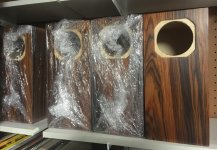
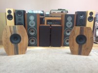
I just picked up a Fisher 800-C, a Garrard turntable, and a pair of 16" alnico woofers (maybe fisher, all I remember is that they said "oakton" on them, will get them tomorrow) out of a console I bought with lunch money. The older gentleman purchased this new and said it was "top of the line" when he got it. It still has original Fisher tubes installed, absolutely mint. It has not been powered up in at least 20 years. I love this country.

I found this post on stevehoffman.tv and I'll repost here because it seems great advice. I have minimal experience in electronic troubleshooting, none with tubes. This is my second tube amp ever, the first doubled as a rat's nest at some point in time, so I've been reluctant to do much with it, this baby has project potential, I'm willing to dive in and do whatever is needed for complete restoration.

If anyone can contribute with hints and suggestions, I would greatly appreciate it. A photo will be provided shortly.

Is the "dim bulb test" a light dimmer? Will that be a good substitute for a variac, because I don't have one. I do have esr tester, a good meter, and will most likely acquire an o-scope shortly.

******************************
Posted by Hegeman's Ghost

Adrian,

If you take it to a local repair person, be sure he has tube amp experience. If you don't mind shipping the amp. there are a few qualified people who you could send it to for repairs. If you are interested in the latter, email me off line and I will provide you with contact information.

Following is a list of the steps that I follow when bringing up a vintage amp/radio/receiver that I have just purchased.

1. Open the unit and inspect the electronic components and wiring. Look for broken or loose wires, leaking capacitors, burnt or badly discolored resistors, etc.
2. Check the power cord. Make sure it is not frayed or broken.
3. Hook an ohm meter to the prongs on the plug(unpluged of course). A reading of 5 to 20 ohms is normal.
4. Check the fuse. Is it good and is it the correct amp rating for the unit. I'm guessing your unit would use a 3 amp fuse.
5. Clean all of the pots and switches with contact cleaner.
6. Test all of the tubes on a reliable tube tester.
7. Clean all of the tube tines and tube sockets with contact cleaner.
8. Clean all of the inputs, and outputs with contact cleaner.
9. Use a variac or dim bulb tester to power the amp up slowly. I start at 20 volts, then go to 40 volts, 60 volts, 100 volts, and finally 120 volts. Obviously, if you blow a fuse at any of the lower voltages, don't go higher until you find out what caused the problem.

In your case, you have already applied 120 volts and the unit took it without blowing a fuse. So it is pointless now to worry about bringing it up slowly.

Question, have you hooked the unit up to a turntable or cd player and tried to pass a signal?

After you do steps 1 - 8 above, you might want to try this and see what happens. You can't imagine how may problems are simply the result of dirty pots, switches and sockets in equipment that has been sitting idle for years.

By the way, if you don't have a tube tester, skip item 6 on the list. If they are new tubes, it's unlikely that both channels will have a defective tube.

Good luck, HG

Re-use Audio Nirvana MkII 2.8 cu. ft. cabs for Eminence Beta-10CX coax drivers, or ..

I am looking for advice on how best to re-use the Audio Nirvana MkII 2.8 cu. ft. cabinets I have built for the AN Super 10 Ferrite drivers. You can see the picture of the cabs here: DIY Full-Range Speaker Kits High Efficiency Speaker Audio Nirvana - 38.5T x 12W x 13.75D inches with a 6" port hole at the bottom. I am driving these with a 15 Watt DIY KT88 tube amp that a few folks have recommended on this forum (built using the great instructions by Blueglowelectronics: Sketches & Info | Blueglow Electronics), and I like this amp a lot!

Now to the speakers, I do like how sensitive and easy to drive the AN 10's are, but I am growing tired of the general brightness of them. As I already spent time and effort on building the cabs, is it at all a good idea to reuse the cabinets by let's say replacing AN's with Eminence Beta-10CX 10" Coaxial Drivers with PSD:2002S-8 1" Titanium tweeters and the PXB2:2K5CX 2-Way crossover at 2,500 Hz? All these are readily available from PE at reasonable prices. Eminence even provides recommendations implying that combo should be good in PA mains: https://www.eminence.com/pdf/Eminence_DIY_Home_Hi-Fi.pdf

Do you have opinions on how the final result would sound? Or would that be a complete waste of time and money, and I should just move on to build something tried and true, for example Zaph's ZDT3.5 speakers?

2 EV or not to EV ?

Good day, everyone.

I have a couple of questions and thought this would be the best community to get some answers.

A couple of years ago I had a couple of JBL 2226's, a couple of EV DH1A's and a couple of B&C DE250's laying around. I found someone online who knew how to build and finish quality cabinets, combining these components and, along with a custom crossover, bringing new life to my listening experience. They are part of my home theater setup along with Focal and Polk and being powered by Arcam.

The frequency response is beyond what I though it could be. The 2226's are crossed over around 800Hz where the DH1A's carry to 3Khz and the DE250's take it from there. The crossovers have pots so I can adjust when things are either a little bright or not enough, and I absolutely love the sound and how low they actually play.

While watching a movie the other day, the sun was poking through my blinds and hitting one of the 2226's. There was a lot of low-end rumbling and explosions in the movie, which I like, but noticed the cone on the speaker moving quite a lot. I know this is normal, but I started thinking about maybe having a dedicated subwoofer(s) to help support and complement the 2226's and cross them over around 50-60Hz.

I have some other components just sitting in my basement right now doing nothing but collecting dust...they are 3 Electrovoice EVX-180B's.

I've read some other reviews on them and asked my friend about designing something to house 2 of the EVX-180B's, as there were favorable comments on them playing down to 27Hz. He, in turn, stated that the JBL 2226's could probably use the help around 50Hz, but that the EVX-180B's are not much better than the 2226's, and that I should consider selling them and getting something better.

Can anyone here assist with any information (pros/cons, different drivers, different cabinet designs, etc.) about this? I'm open to ideas and it would be greatly appreciated.

Cheers

Attachments

  • DSC_0255.JPG
    DSC_0255.JPG
    322 KB · Views: 219

Onkyo 7030C / Nad T753 Discrete Op Amps / IC Op Amps

Hello All.
New member here - first of all while I do enjoy decent hifi it's always been at the budget end, and my experience in electrical work has been limited to (recently) changing a capacitor each on a Meade telescope handset and a Roland JV 1080 synth expansion card.
I cannot read schematics etc so consider me a complete newbie please.

My home theater receiver is a 20 year old Nad T753. I love the sound of Nad, having used them in the UK before I moved to the States.
My CD player is an Onkyo 7030 C. Budget end but well respected apparently. Had it for around 6 years.

A few weeks ago (on a Facebopok hifi group) I saw Discrete Op Amps mentioned.
Not having heard of them I looked them up and started some research. I wondered if I put a few in my Nad and/or the Onkyo I'd improve the sound.
I stress I'm not unhappy with the sound but with a few cheap tweaks wondered if I could improve it.
That was....until I saw the sticker price of a single Discrete Op Amp.

I'd downloaded the Service Manual for the Nad and it showed 9 IC NJM5532M Op Amps (the DAC is apparently a Cirrus Logic CS4340).
I opened up the Nad yesterday with a view to confirming the above - but no way am I trying to take this apart - I'd never get it back again.

I looked inside the Onkyo and that shows 5 Op Amps - JRC 4580D's (assuming I got that right with my magnifying glass).
The DAC looks to be a Wolfson WM 8718S.

Would I likely get any improvement if I had drop in replacements for the JRC 4580D's. Another IC Op Amp? If so what would be suggested as a replacement?
If I changed out any IC Op Amp's for a Discrete - I'd be tempted if I could change just one. Is that possible? Would it need more than that?

I could instead put the Discrete money towards a Cambridge Audio DacMagic ($200). As said - the Nad DAC is a Cirrus Logic CS4340, with the Onkyo being a Wolfson WM8718S. The DAC used in the Cambridge Audio is apparently a Wolfson WM 8742.
Am I going to get $200 worth of difference here? I currently use the Onkyo DAC - I have switched between the Nad/Onkyo - there seems little difference.

I have looked at a few threads here -I have seen some for and against the Discrete versions and if anywhere - due to cost I'm leaning against. Tempted but probably no more than one.

Finally - I'm also tempted to upgrade the Nad. A Nad T758 or a Marantz 7015 are on a shortlist. I'm leaning towards the Marantz as Nad's quality control seems to have some criticisms (and I have experience with that too).
Neither are out just yet and I'm okay with keeping the 753 a while longer.
Any advice on the above is appreciated, and apologies for the length of this - went on a bit longer than I thought it would. 🙂

Adcom GFA-555 II Amp Oscillating

Bought a defective GFA-555 II off EBAY. Right Channel was good, Left channel was dead and the instan. Distortion LED was on.


I replaced Q107 & Q108 and the left channel came back to life.


I replaced all the elec caps.


I biased both channels and they came in right at 1mV.


Output DC offset is less than 1 mV on each channel.


When I tested the amp in bridged mode, 1 kHz signal into an 8 ohm load, when the output was at about 150 watts, it went into oscillation and blew a fuse.


It's done that twice now.


When I replaced the fuse and test again in Stereo everything is fine.


Any ideas what I should check/look at? I'm guessing a cap somewhere but not sure.


Thanks for the help,
Gary

Protection cap for my precious new compression drivers?

A couple of weeks ago I go a good deal on some 18Sound ND4015be 1.5" throat 4" Beryllium diaphragm compression drivers and now have them installed in some JBL 2384 horns driven by Aleph J in a Bi-Amp active setup. Beautiful sound! BUT, Aleph J has a noticeable switch off thump and although I have a mute switch on the amp when I power it down I am concerned that a power outage or an error could send this thump to my Be diaphragms 😱
So I guess a protection capacitor is needed? Crossover is 630Hz so if I go an octave below that I'm going to need quite a large capacitor!
Any suggestions as to a good cap for this job? They sound so good I don't really want a capacitor in the signal path to affect anything 😀

My KISS LM317/LM337 Regulator

After looking around the forums and copying a few good ideas I'm taking my first shot at PS design so be nice! My goal here is to build a very basic +/-12 supply capable of delivering 100ma or more and fit on a smallish PCB. I realize the sky is the limit in regulator design but I'm trying to master the basics here and build on that later. The only suggestions I'm pondering right now, but I'm open to others, is whether I need to keep C5 and C6 and where to find some 'high ESR' electrolytics for C9 and C10?

Regards,
Dan

attachment.php

Attachments

  • Mythirdattempt.jpg
    Mythirdattempt.jpg
    177.9 KB · Views: 2,015

What's with the watts?

  • How do manufacturers get away with ridiculous claims? I will use any crap as a test amp but my latest acquisition takes the biscuit. A Samsung A/V amp claims to consume 75w.

    However, according to the specifications, using some highly-classified nuclear cold-fusion technology it is apparently capable of delivering 170w to the subwoofer channel. 166w to the centre speaker, 333w to the fronts and 333w to the rears.

    My old Yamaha YST-PSW-60 subwoofer, claims to consume 70w, and output 50w. Strip it down and you'll find "Taiwan 25w" stamped on the driver.

    I understand the difference between RMS and PMPO but this flagrant deception is ridiculous. It's akin to Ford claiming the new Focus does 15,000 mpg (when dropped from a C130 with the engine off).

    Rant over.

FS: Delrin thrust plate for Technics 1200 spindle bearing

I bought this new from KAB Acoustics and put about 200 hours on it. They are $46.95 + shipping on the KAB website. I ended up buying an IanMac bearing and don't need this so I am selling it before I lose it.

$25 shipped in the continental USA. PayPal only.

This is for the 1992-2010 Technics SL1200. I had it on a 1999 SL1200-M3D.

attachment.php


attachment.php

Attachments

  • 20200828_185053.jpg
    20200828_185053.jpg
    112.7 KB · Views: 491
  • 20200828_185100.jpg
    20200828_185100.jpg
    122.9 KB · Views: 462

Possible conversion into Current Amp?

Hello you Solid State Guru’s out there. Your expertise would be highly valued, since I need your help and input in order to attempt to do a bit of experimenting with an existing ancient power amp. The amp that will be victimized was published in the Elektor’ Summers Circuits in the 80ties. The circuit, featuring the famous Quad 303 Triple output stage, has been discussed in the thread “Amplifier based on 2N3055”. I built these entirely from spare parts around 1987. Surprisingly, this is one of the few Elektor power amps I built in those years that functioned flawlessly without oscillations or other annoying side effects right from the start. The amps have been gathering dust now for some 30 years. Member Madaudio shared a somewhat stained copy of the circuit, which I reuse here. See below.

The first question I have before possible conversion into a current amp is: could the feedback capacitor, C3/4/5, which is now approx. 2.5 uF, be increased to 100 uF without limiting the functioning of the circuit? Reason is I would like to have as little phase-lead as possible in the DC-100 Hz area for the first step of my experimenting.

Main thing is: I would like to convert this Amp into a Current Drive Amp for some experimenting with 4 Ohm woofers. Basically some experimenting with low Qts woofers, but with high Qts in-box characteristics because of current drive. Bandwith needed will not exceed 1500 Hz. For that reason I would like to leave out the Zobel. To clarify my purpose: This has nothing to do with subjective issues as how Current Drive is supposed to sound, but only about woofer-amplifier interaction and investigating the woofer transfer function around in-box woofer resonant frequency. With this background in mind, I do not intend to modify other than necessary for transformation into a very basic Current Drive amp.
Could this circuit turned into something like the Joe Rasmussen Transconductance Amp as attached?

Or this: Member Adason hand drawn schematic.

General question: What should be done to turn this circuit into a working Current Drive Amp for use with a woofer-only?
Thanx for any input and help.


Eelco

Attachments

  • Elektor2N3055.jpg
    Elektor2N3055.jpg
    339.2 KB · Views: 429
  • Trans_Amp_Schema_Wiring_Caution.gif
    Trans_Amp_Schema_Wiring_Caution.gif
    25.9 KB · Views: 465
  • CurrentAmp_adason.jpg
    CurrentAmp_adason.jpg
    671.2 KB · Views: 432

Questions about a Lundahl & a Sterling ST69

Hi there, new DIY guy here. I was hoping to change out the output transformer in my ST69 with a Lundahl. I've done the switches with ribbon mics no problem, and make the assumption switching the output would be fairly easy. Needless to say, I have learned my lesson.


I grabbed a Lundahl LL1940 (it being the "Lundahl Tube Transformer"). I've tried following the pinout guide given by Lundahl, but to no avail. Any help would be appreciated. Just trying to learn here.

FS: Wild Burro Betsy’s and/or Baffles

Hi guys,
I just purchased a brand new pair of Betsy’s with the idea of mating them with some H frame subs, but before doing that I decided to build some baffles similar to those found elsewhere on the web.
I love the Betsy’s and I still plan on building some subs, but in the meantime I have these for sale.
The wood is 7/8” solid oak with a walnut racing stripe. I have the baffles sloping back at 6 degrees. They sound amazing but do taper off at 80hz.
If anyone is interested, $200 plus shipping for the woodwork, or
$300 plus shipping for the whole assembly.
The pair weighs 25lb without packaging, so you can estimate shipping cost from my zip code, 28901.
Stay safe,
Peter

Attachments

  • 7C4D80B6-51C1-4F88-8D2C-DF91262B00E7.jpg
    7C4D80B6-51C1-4F88-8D2C-DF91262B00E7.jpg
    522.9 KB · Views: 342
  • B462859E-BF40-4F04-A03D-BA46270FCBE0.jpg
    B462859E-BF40-4F04-A03D-BA46270FCBE0.jpg
    547.5 KB · Views: 337
  • 7D4AA218-567D-4D07-87DC-7E462D2E2DA8.jpg
    7D4AA218-567D-4D07-87DC-7E462D2E2DA8.jpg
    461.8 KB · Views: 341
  • CED76832-E420-4555-B4DD-02EB5C04CDBB.jpeg
    CED76832-E420-4555-B4DD-02EB5C04CDBB.jpeg
    907.4 KB · Views: 355

Really tight octal socket

I got myself some of these sockets. They look nice and high quality, I was hoping for them to be better than the usual cheap loose wobbly kind.

It turns out they are on the other extreme. I only have 2 types of octal tubes, a Sovtek 5AR4, and a pair of Guiguang KT88. I can get the 5AR4 to sit all the way in, but I need tool to remove it afterwards. The Chinese KT88 I can't even get them all the way in.

I was hoping to to remove the nuts on the pin to loosen the jaw. I tried with a small plier but it won't do. I don't have (and never seen) a wrench that tiny

Any tips to loosen them up? I was pushing the tubes in and out but I think I will eventually break something.

Anyone have experience with them? Will they eventually loosen up? Or am I better off with the cheap wobbly kind?

Attachments

  • 1.jpg
    1.jpg
    125.5 KB · Views: 310

Point source omnidirectional speaker.

I’m fairly new at speaker building and shy away from many traditional designs looking for something different to work on.

I have found a liking for omnidirectional speakers. After make my first I realise the 6 speakers caused an amount of lobing that I seek to try to eliminate.

I researched what is available on Apples HomePod and they seem to use 7 drivers for mid/highs without noticeable lobing effect.

I am working on a larger beast with 12 inch subwoofer down facing and 16 mini speakers using load folded horn design as shown in the picture. Dsp will flatten the speaker freq response.

What should I be looking out for to get the best omnidirectional point source response? Appreciate your experience and comments.

Cheers
Tony

a27d24_d2c984bf1bfc459a919ebb5b9c499af7~mv2.png

FH3 - Best Alpair 7.3 alternative?

Hey,

I am based in UK and very keen to build myself a pair of FH3s. Unfortunately the Alpair 7.3 isn't available anymore over here.

Anyone have any views on what would be the best alternative out of the Alpair 7 MS and the Pluvia 7.2 HD? Or any others worth considering? I've not been able to find much about these newer options specifically considering the Frugalhorn 3.

Best regards

gmarsh Weiner TPA3118 Stereo Amp and Weiner PBTL Mono Amps

D5B78032-73F3-42A9-B72C-96264A0F43AC.jpeg
6114C303-31B6-43C7-99C4-5124C39F823E.jpeg
56F29F2C-8794-45D9-9D8F-BE545A2B2381.jpeg
E4341ED3-865B-4B42-A863-C4201CD00CCD.jpeg

gmarsh-built Weiner TPA3118 stereo amplifier
Complete amplifier with two Cinemag CMLI-15/15B2 input transformers...$120

—————————————- OR ——————————————

Weiner TPA3118 stereo amplifier module only.........................................$40

gmarsh-built Weiner TPA3118 PBTL mono amplifiers, pair.........................$80

Upgraded Astron RS-12A 120VAC/12-13.8VDC power supply....................$50

Will only accept PayPal payments. Will waive PayPal fees. Does not include shipping via USPS Priority Mail to continental US.

Selling these lure at-sounding Texas Instruments Class D amps, because I have too much audio gear.

Is this circuit a capacitor multiplier a regulator or neither?

I found a project article that promises to reduce ripple greatly at a fraction of the heat dissipation of a regulator. The author sets this up for low voltage supply. I have a few questions... Is this a regulator or some type of capacitor multiplier, or neither? Also what mosfet would I use if I wanted to scale this circuit up to handle B+ level voltages? It looks promising to me as a preamp DC filament supply as it wouldn't dissipate as much as a regulator and regulating filaments isn't really critical anyway. For B+ it looks like a simpler alternative to full out regulation, a middle ground between unregulated and regulated?

An Alternative to Linear Regulators: Equivalent Power-Line Ripple Rejection with Less Power Dissipation | audioXpress


Thanks

Novice help putting together a preamp

I have lurked here for a long time and am posting for the first time. I hope you don't mind entertaining some very rudimentary questions. I have built lots of speakers over the years and a few electronics, both tube and solid state, from kits, but it has been a while. I have no EE background but I can solder and read a schematic and work on a circuit without going to the ER. I am working on educating myself on tube circuits, including reading Kevin O'Connor's book. I am hoping to build a preamp/phono from some off-the-shelf circuits I have already. I have both the preamp boards from Ken Stapleton. He specifies that the linestage requires 285/265/6.3 and the phonostage requires 285/245/6.3. I spoke with him fairly extensively over email (super nice guy, BTW) and he says for the 245 and 265 you can meet somewhere in the middle to power everything with one power supply.

I also have the tube rectifier power supply kit from John Broskie. I am not dead set on using this power supply, but I have it and it is much more approachable to me than building one from scratch. I'll attach his schematic below, but it is not my intellectual property to please let me know if that is against rules or etiquette. I am wondering if someone could please point me in the right direction of figuring out if this power supply would be appropriate and what transformer values I would need to get it there. I would like to use dc for the heaters, and I am very confused about how he is handling that since he shows considerably higher voltage for the heaters. Additionally, I'd like to know what to look for in a choke to use, but if appropriate that can be another thread. I still have some reading to do on that front.

Thanks, guys.

ps-tube-9.gif
Projects by fanatics, for fanatics
Get answers and advice for everyone wanting to learn the art of audio.
Join the Community
507,827
Members
7,889,912
Messages

Filter

Forum Statistics

Threads
406,326
Messages
7,889,912
Members
507,827
Latest member
Sus12