Exotic iwata/JBL loudspeaker pair fo sale

Well I’ve broke my own heart. My wife and have decided to move our household to Europe and now I have to sell off my favorite toys. In this case my pair of JBL cinema cabinets with IWATA 300 fiberglass waveguides from Auto Tech in Poland. The compression drivers are JBL commercial cinema loaded with TrueExtent berryllium diaphragms. I tell you the sound is truly magical! I got four UREI 6250 amplifiers that used to power that I amthrowing into package. Their condition is absolutely pristine. You will never hear a better stereo. The last time that I measured them, they were quite flat from 40Hz to 18kHz and had no trouble reproducing authentic theater sound tracks. Unfortunately I cannot ship these. The buyer will have to come to my home and pickup. To offset the hassle I am offering the whole package for $2,500 total. How is that for a deal?

I also have two JBL commercial cinema subwoofers. They feature 18 inch drivers in a cabinet 4 cubic feet. They are very clean to 40Hz in most rooms. I will sell these two cabinets deep discounted. They work

very well with the described loudspeaker pair.

Should anyone have an interest, Please let me know

Attachments

WM8805 problem

Hi.
I've been playing with wm8805 chip lately and i really love the sound of that chip but i cant get it to lock on anything higher than 16/44.
If i play higher res.like 24/96 Files the sound gets hiccups and if i play 24/192 than i get no sound and lots of crackles.
Im using spdif input with cap in series and 75ohm to ground. ...the chip is connected to wm8741 dac (i2s).
The chip is setup in hardware mode and it suppose to support all data up to 192.
...i cant figure out what im doing wrong.
But it sound amazing with 16/44 files.
Has anyone experience similar problem with wm8805?, if you have any suggestions please let me know.
K.

Question about calculating power dissipation

Hi Folks,

Great to be here, and this is my first post!

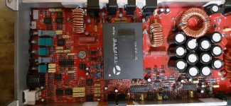
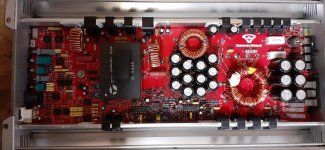
My company Pangolin manufactures laser equipment, including servo drivers and laser scanners.

We use LM3886 as a part of our servo driver. Our servo driver is like an audio amplifier, and our scanner (motor) is like a speaker. Our laser scanners have impedance properties similar to a speaker, so the LM3886 works well for this application.

The LM3886 is incorporated into a digital servo driver. This servo driver has a multi-channel A/D, and with a high sample rate, we digitize both the voltage coming from the LM3886 output, and also the current flowing through the scanner's coil (current that is ultimately provided by the transistors in the LM3886).

Digitizing the voltage and current provides great insight towards our servo system operation. I can graph these over time, and create oscilloscope waveforms of various quantities, including this voltage and current. We can also perform "math" on these, and graph related quantities.

For example, we calculate the average power dissipated (heat generated) by our scanner (like the speaker in an audio system). To accomplish this, we simply do RMS Current squared, multiplied by the coil resistance. (One way to get Average Power is I^2R.) Since we digitize the current, it's easy to do an RMS computation on the samples and obtain that quantity.

We'd also like to calculate the actual power dissipation (i.e. heat generated) on the part of the LM3886. In other words, I'd like to calculate the average power. But for the power amplifier, I'm having trouble wrapping my head around how to do that. It seems a bit more tricky.

The question is about calculating power dissipation (watts) in real time based on data samples.

-------------------------------------------

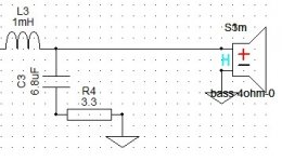
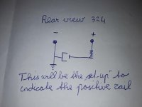
As I mentioned, our servo driver has digitizes both the voltage that is output from the power transistors to the motor coil (we call this "Instantaneous voltage") and also the current flowing through the motor's coil (we call this "Instantaneous current"). We sample these quantities very often, so at all times the servo driver is aware of the instantaneous voltage and current.

I'd like to calculate the heat generated by the power transistors while they are supplying current to the coil.

Presently my way of calculating this is shown below.

if(InstantaneousCurrent >= 0)
{ //Current is positive -- must be coming from the positive transistor
InstantaneousTransistorVoltage = (PositiveRailVoltage - InstantaneousVoltage); //For example, 24 - 21 = 3V
InstantaneousTransistorPower = InstantaneousTransistorVoltage * InstantaneousCurrent; //For example: 3V * 3A = 9W (Power = Voltage * Current)
}
else
{ //Current is negative -- must be coming from the negative transistor
InstantaneousTransistorVoltage = (NegativeRailVoltage - InstantaneousVoltage); //In this case transistor voltage will be negative (-24V - -21V = -3V
InstantaneousTransistorPower = InstantaneousTransistorVoltage * InstantaneousCurrent; //For example: -3V * -3A = 9W (Power = Voltage * Current)
}
AverageTransistorPower += CurrentFilterConstant * (InstantaneousTransistorPower - AverageTransistorPower);


So, in other words, for each sample, I take the instantaneous voltage through either the upper transistor or lower transistor as applicable, and multiply it by the instantaneous current to obtain an "InstantaneousTransistorPower", and then average that over time.

Alternatively I could calculate the heat in the upper transistor if(InstantaneousCurrent >= 0), or heat in the lower transistor, and then sum the two together.

Either of these techniques make intuitive sense to me.

--------------------------

But then, just today, while searching for "calculating average power", I see "Average power = VRMS * IRMS". So, they're multiplying the RMS of each.

My code presented above above makes intuitive sense, but it deals only with the average. So it would be like "Average Power = Average Voltage * Average Current". For sure Average isn't the same as RMS.

So here's the question for all of you folks on DIY Audio: Should I be calculating the RMS voltage that appears across each transistors, and multiplying that by the RMS current flowing through each transistor (and then summing the upper and lower transistors)?

Note that sometimes the current flows through the positive transistors, and sometimes through the negative transistor. In the case of the LM3886, both are in the same physical package so I don't care too much, and it's all about the heat that is being generated, and thus must be dissipated by the user.

---------------------------

Best regards,


William Benner

Strobe Sony PS-X9

I have already had some help from members in the past for which I am grateful, however I am still stuck 🙁.

After resoldering the power supply and NEON power supply, and measuring the voltages, Q701 (2SC1431) doesn't have the right values (resp. B=36v, E=53v, C=240v). According tot the service manual it should be 155v, 157v, 220v. I suppose that's the reason Q413 doesn't measure right either.

Does anyone have an idea what might be wrong? 😱

Attachments

Heat Sinks

How do we connect a heatsink in an amplifier? Or to an amplifier module?

Does it matter where it goes in the case? DOes it have to attach to the module or can it just run along the sides of the amplifier case?

Why I ask is because the UCD400 Hypex module has a part in which I have seen it connected. While many other module don't have this. So just curious where I put the heatsink in the amp casing?

Finemet OT Trafos

Today are arrived the firsts FINEMET C nucleus from Hitachi distributor.
Three types for different use, one p-p, one SE and one fro MC step up.
Soon I will have the protos to check and the intention, if they seems fine, is to produce a line of trafos.

Walter

ps: it is funny that I am a Hitachi employee ( on computer company inside the Hitachi galaxy)

Attachments

  • IMG_5381.jpg
    IMG_5381.jpg
    830.6 KB · Views: 981

Aleph 1.2 questions (soon done)

I will soon have completed my Aleph 1.2 project. I will at a later stage post images and so on, but for now I have some questions.

1. Each PSU concists of the following. I have 2x625VA trannies with 45v secondaries. This goes into a capasitor bank of 8x66000uF (the psu is based on KK's design). My first question is: Will a thermistor do the job as an inrush limiter? I currently have a couple of CL-10s that I got from my supplier that I was thinking of using. If these thermistors are far from enough (my worry), can someone please help me with (direct me to) a sufficient softstarter or something that will work?

2. The capacitors are all Mallory cans. Original I was told. As they only are rated for 60VDC with a surge of 75VDC I was thinking of taking the voltage down to 58VDC by the use of power resistors. First of all, is this safe? ( I don't really get understand the rated versus the surge value) Secondly should I try something else? I used a variac and got 58 VDC out of one capacitor and one 625VA, the primary side was then 215V. As the secondaries are ca. 46 volts I was thinking of using a 1.7-1.8 ohm resistor to bring down the voltage to 58-59VDC. Any comments will be appreciated!

It may seem that I have taken on a too difficult project. This is true, very true. But the last 6 months have been spent worrying, waiting, building and more waiting, and in the not to distant future I will hopefully have succeded. (I have some helpers), so please don't be too frustrated with these questions...

Thanks for all your help!

Folke

Needed... Tube amp top covers

Greetings everyone.

I am looking for the top covers for two of my tube amplifiers.

A.- Harman Kardon AX20 – Nocturne.
Width: 12-1/2”, Depth: 11-1/2”, Height: 3-3/4”.

B.- Stromberg Carlson ASR-333 (same chassis with ASR-433).
Width: 13-1/4”, Depth: 13-1/2, Height: 4-1/4”.

If any of the esteemed members of this forum has a spare cover of these dimensions and is willing to part with it for a reasonable price please let me know.

Alternatively, perhaps some of you know where I can buy the perforated metal sheet or some suitable metal mesh to make a decent cover. Any suggestions will be greatly appreciated.

Thank you for reading this and for any offers or suggestions.

Resistor design?

Spent extra time & $$ sourcing carbon composition resistors for EL84 PP project attempting to minimize noise. Most values were not in tolerance- especially from ebay vendors.
Investigating using carbon film or metal film for next build- any noise advantage of carbon comp's vs those other designs? Film resistor tolerances seem to be much tighter- perhaps beneficial in PP design for balance.
Thanks,
Jim

helps to know erased circuits, planet audio RXD1400 amplifier module.

Good afternoon, I request your collaboration and help with this amplifier of the brand planet audio model RXD1400, I repaired the source but when testing the digital output mosfet transistors, I found that the module was not switching, it is a black module covered in epoxy, I was able to dismember it but it turns out that it has the license plates erased, it is only possible to see two integrated, I attach some images.

The politics

Found and joined this site after being ridiculed for posting a tube amp build on another site...

Not looking to start an episode- but these are my reflections when thinking back to previous acrimony-

Just received my copy of 'the absolute sound' which- in my assessment, is an "If you have to ask the price,,, then you can't afford it" audio connoisseur mag.

Thumbing through 152 pages-
9 inks/mentions SS amps/preamps
11 of tube
4 of unknown

Concluding that SS DOES have solid ground in the industry and is beneficial... My preamp tone control front end is NE552... But high end audio DOES includes tubes... rest my case.
Jim

Moray James' Karlson 1/4 wave T-line cabinet for FE167E, etc.

Long time Karlson experimenter Moray James made this innovative little design back in the days when Job Ulfman's Karlson Speaker forum was active and took it to a Hi Fi show in 2004.

(Moray had a stoke this past July with complications so we can give good thoughts and praters towards a full recovery - plus there is a GoFundMe where one might help a bit with things). Fundraiser by Rachel Zhang : Support Moray to go through challenging times

At a later point, Moray "raised" the wings so their lower intercept was with the top of the speaker. Myself, being a stubborn/strict Karlson interpreter, would experiment with aperture flare, top gap, and probably XRK971's suggestion of Melamine sponge pads.

The cabinet's picture taken from the front may be one of Moray's other designs as its aspect appears taller than the one featured in the plans. I'm sure he'll clarify.

With Moray's kind permission, I present details for that design

Attachments

  • Cutaway2 Web.jpg
    Cutaway2 Web.jpg
    236.9 KB · Views: 236
  • Damping line 1.jpg
    Damping line 1.jpg
    55.9 KB · Views: 234
  • Damping line 2.jpg
    Damping line 2.jpg
    47.3 KB · Views: 230
  • Front one Web.jpg
    Front one Web.jpg
    154.5 KB · Views: 240
  • FRONT1 2X.jpg
    FRONT1 2X.jpg
    159.2 KB · Views: 231
  • Side1Web.jpg
    Side1Web.jpg
    237.8 KB · Views: 151
  • TopView web.jpg
    TopView web.jpg
    154.4 KB · Views: 140

8600S Thank you Vkung!

Hi Everyone!

Been a lurker for awhile, and decided to create an account to reach out to some people to start a project. After a some reach pointing to the 8600, I decided to reach out to Victor for some insight into the kit. He might be the best customer service and fastest responses I have every gotten with any product in my life, DIY or not.

So I ended up ordering a 8600S with upgrade Vcap cutf couping caps, and a pair of Psvane Acme 300b + siemen 12au7. The build in it of itself is extremely straight forward, and the minor areas of confusion were explained in detail by Victor. He responds in about 5-10 minutes max. If you have soldered before, honestly it is an extremely straight forward build. Take your time and double check everything. Go back under a light and make sure all your solder is properly flowed, and everything is in the correct place before closing everything up.

She fired right up, and sent off my measurements to Victor for a quick look and everything was within range.

Impressions:

I am using this mainly as a headphone/computer amp. I will probably be doing a DIY speaker build over the next few months to make sure of the speaker outs as well.

The amp was a bit on the bright side and harsh around the edges, but I could already hear the open stage and extension in the upper and lower registers. Remembering that many of the components require significant burn in, I stopped listening after about 10 minutes and let the amp play at low volumes straight.

At around the 2 day mark, the harshness started rounding out and the bottom end started filling in. The stage was about the range of my previous KT88 amp, but the imaging and details were really coming through. The imaging was better, and everything was really coming in nicely.

At the 4-5 day mark I started tube rolling a bit to get the sound to my personal preferences. ATM my favorite setup is the Psvane Acme tubes + telefunken 12au7 smooth plate x2 + telefunken 12ax7 smooth plate/mullard 12ax7 long plate. I really like to rotate between the telefunken and the mullard as they just have such different personalities they let me remember why I love the other tube so much.

I have let the amp run in at this point about 9 days, and now will stop as I have not heard any appreciable changes. This is my 3rd tube amp for my headphones, and they have all been 2k+.

Black background: 8600s this base covered. its completely silent. go 0 complaints. The tubes i have dont pickup any noise. I have had issues with tube noise and general amp noise in the past.

Details: Best of all the amps I have used.

Stage/imaging: Stage matches the better of my previous 2 amps, but with improved imaging. I do need to explore this again, as my current headphones are not wide staging headphones. I will explore this again when my Verite C headphone comes in the next few weeks.

Extension: The lower end bass is filled quite well with authority and not bloomy. Of course this is something that can be adjusted with tubes to your personal preference. But the 8600S naturally seems to have great extension that is just accented in any direction by your tube choice.

The 8600S is quite moldable in the direction of its sound with your tube selection. I really enjoyed the sound with a full telefunken tube setup for the 12a_7 tubes, and mullards add their magic for a warmer, mid focused romantic sound. 5751 windmill getters worked great as well. I have a full set of bugle boys that I need to test that I havent gotten around to yet. RCA clear tops 12au7, with tungsol triple mica D getter 12at7 sounded great as a budget setup as well.

Not really sure what else to say except that, as much as the amp is amazing, the communication with Victor just took it to another level. This is hands down the best I have heard from a tube amp, and the greatest responsiveness from a representative I have ever had. Its honestly just a really enjoyable listen. Romantic, with all the technicalities intact, and non fatiguing. I can listen for hours, and not exactly sure what else I could ask for in a tube amp, but will be having some of my friends come over for a listening session over the next few months and hoping to get them to transition over as well.

Anyone with knowledge of M&K MX350/MX5000 Drivers?

Hi,

Just about to purchase a MX350 MkII, but had a few concerns and
wondered if anyone could help before I parted with my money...


Seller claims to haver replaced one of the drivers - the front facing one.
It looks like he has replaced it with a model number S30F77 which
correlates to the drivers installed in the MX5000 not the MX350 MkII
(as far as I can tell).

Will this have any adverse quality issues? or were they interchangeable?

Thanks

Light bulb in power trans primary

Hi,
I have a power with dual winding primary of 115V
In series connection this will give me 230V primary.

Question is : is it OK/safe to insert 6v light bulb in between the windings (1st winding neutral -> hot -> bulb -> 2nd winding neutral -> hot) ?

The trans is around 35VA so the current in primary should be around 0.15amp max? I can use higher rating bulb to anticipate some turn-on surge.

The bulb meant to drop the voltage a little in secondary and can also functions as indicator light

Thanks in advance

Onkyo protection mode

I have a Onkyo tx-nr509,goes into protection mode and will show ever so briefly sp wire error code.I have read and researched all threads,videos and i seem to understand some transistors and or channels have shorted.I think one resistor is bad it would spark when i powered up the receiver,my problem is it is 2x .22ohm resistor which has a common pin in middle and two resistor package.I could not find such any more so received two .22ohm 2w resistors,but they only have two pins.my question is how to join these two resistors so they have a three pin common ?Thank you for all your help.One more question in one of my pictures it seems that there is a large transistor,is that what it is?
dWk9MiZpaz1kMGJhNzBjMjJhJmF0dGlkPTAuMiZwZXJtbXNnaWQ9bXNnLWY6MTY3NzcyNTEyNzcxNzU2ODM2MCZ0aD0xNzQ4N2ExZDVjNWEzZjY4JnZpZXc9YXR0JmRpc3A9c2FmZSZyZWFsYXR0aWQ9MTc0ODdhMTU4YWVhNGUxYzI4ODINCklETGlzdD0NCkhvdEtleT0wDQpJY29uRmlsZT1DOlxVc2Vyc1xkYWRcQXBwRGF0YVxMb2NhbFxNb3ppbGxhXEZpcmVmb3hcUHJvZmlsZXNcZ2VvNm9lb2suZGVmYXVsdC1yZWxlYXNlXHNob3J0Y3V0Q2FjaGVceW5MWTAwZHNPOWw2RGprVlZWSHpVdz09Lmljbw0KSWNvbkluZGV4PTANCg==

Attachments

  • received_1477123799148618.jpeg
    received_1477123799148618.jpeg
    263.4 KB · Views: 78
  • received_1710444319120758.jpeg
    received_1710444319120758.jpeg
    173.8 KB · Views: 81
  • received_4348870035188241(1).jpeg
    received_4348870035188241(1).jpeg
    303.3 KB · Views: 83

stability of bias of KT88 in Xindak V30

Anyone know how often KT88 will drift over their life?

I picked up a used Xindak V30 and suspected the tubes needed adjustment. After searching around for a while I found this post in their discussion forum:
»¶Ó*·ÃÎÊе¿ËÍøÕ¾

The image points out the relevant resistors and trim pots to adjust, and seems to mention something about 0.5V, and 50mA, which is consistent with the 10 ohm value of these resistors based on ohms law.

After opening it up, they measured between 0.38 and 0.43V so I brought them back in spec.

Considering the hassle of opening and flipping over a heavy amp, is it worth making these points adjustable from the outside? How often might they drift?

By the way the amp sounds wonderful!

RIAA filter PCB

Hey everyone.


I recently designed my first PCB.

It's an RIAA filter circuit. The boards are 25mmx50mm (~1x2 inch). They are mono because I design my amps symmetrically.

As a special offer to fellow diyAudio members, I'm offering a pair of empty boards for 5$ USD shipped anywhere I can send mail to.

I will also offer the same as a kit with 5% tolerance parts rated for tube or SS duty to anyone here for an additional 5$ for a total of 10$.

For another 5$, I will assemble and test the boards for you.

The blank is being offered for those who want to use exotic parts.

Due to the spacing of the board, I recommend you use nylon screws or at least nylon washers.

If you get a kit, you will need 33nf - P=15mm, 2x 0.1uF - P=7.5mm, 1000pf - P=15mm. Any resistors up to 1/2W will fit these boards. The connectors are standard 2 pin 5mm spaced blue screw terminals, or you can solder directly to the board...

If you're interested, send a PM 🙂

The parts I include are suitable for anything that has a Zout of 600R or less, but the topology is the topology. You can change the values to suit your individual filter design goals.
Cheers!
Koda

Attachments

  • RIAA-Filter.png
    RIAA-Filter.png
    6.3 KB · Views: 142
  • PCB_riaaatest_2020-08-29_13-36-07.png
    PCB_riaaatest_2020-08-29_13-36-07.png
    11.2 KB · Views: 134
  • 2020-09-13 16-53-33.jpg
    2020-09-13 16-53-33.jpg
    537.4 KB · Views: 122

Rockin' the KaZba Dipole (K aperture Z-baffle Dipole)

Here is an idea that I have been toying with for a dipole with really uniform dipole polar responses in the mid and higher frequency regions. Much of this was Freddi's inspiration and we got to thinking that given very uniform polar response that a K-aperture provides, what if we use this to enforce a sort-of slot loading on an open baffle or SLOB? Many people like the sound of a dipole, and have used various means to make the bass units more compact (H baffle, W baffle, SLOB, etc). Adding these enclosures around the baffle to enhance bass starts to affect how the dipole nature of the higher frequencies behave, making them less of a dipole.

To remind you of what a K-aperture can do for polar response, take a look at the data from the XKi (5dB variation over 45 deg off axis up to 10kHz):

461843d1422331652-xki-xs-ab-initio-karlson-6th-order-bandpass-xki-rs100-4-tape-neweq-polar.png


So here is the general concept of the Karlson-aperture Z-baffle dipole, or KaZba Dipole. The Z configuration provides a couple of advantages: angles the driver relative to the K-aperture to reduce resonances, makes the structure stiffer with a big inherent brace, allows the mounting of a second driver in push-pull to reduce 2nd order suspension hysteresis harmonic distortion, and just plain looks cool.

470112d1425731040-rockin-kazba-dipole-k-aperture-z-baffle-dipole-kazba-sketch1.png


So this can be implemented with a pair of full range drivers of any size really, but since we want some semblence of real bass, I am going for 8in drivers. I will be using woofers for the prototype - I am picking some relatively low cost units and so found these buyout 8in units from PE (5 mm xmax, 88dB, 8ohms, is not bad and moderate Qts and $10 ea - the price is right) http://www.parts-express.com/wfr800gs-8-poly-cone-rubber-surround-woofer-8-ohm--299-343. To this, I will add a whammy of an upper end dipole - where it makes all the difference: a Heil ESS AMT. The Heil AMT is a world-class tweeter that is almost full range, able to go as low as 600Hz. I will probably cross at about 750Hz in a 2-way. The KaZba, hopefully, will provide a nice wide bandwidth and smooth response up to well past 1kHz and be an excellent match. The woofers will be driven in parallel so sensitivity should be about 94dB at 2.83v.

Attachments

  • kazba-sketch1.png
    kazba-sketch1.png
    155 KB · Views: 10,577

FOCAL specs Bass and Midbass drivers from the 80's?

I highlighted the 8C412 woofer and the column headings.
Hope they are readable on screen?
May need to download them and zoom in more!

Attachments

  • Vintage Focal Bass-Midrange specs A_Page_3.jpg
    Vintage Focal Bass-Midrange specs A_Page_3.jpg
    916.3 KB · Views: 170
  • Vintage Focal Bass-Midrange specs A_Page_2.jpg
    Vintage Focal Bass-Midrange specs A_Page_2.jpg
    853.7 KB · Views: 160
  • Vintage Focal Bass-Midrange specs A_Page_1.jpg
    Vintage Focal Bass-Midrange specs A_Page_1.jpg
    954.8 KB · Views: 173

New project: Yamaha A-S500 clone

Hello to everybody!
I decided to build Yamaha A-S500 clone. I think it is very exciting (for me)!

I did PCB board is Sprint Layout, I soldered almost all components and I connected it to power. No explosion! Yay! But resistors R136 and R137 got super-hot, so I disconnected it from power. The reason is I did not connected several parts, because I thought they are not necessary, but obviously they are.

The question is: What parts can be removed? I mean parts linked to speaker protection. (I will have an independent module for speaker protection.)
I ignored all parts after 0.22Ohm 3W cement 3pin resistor. Now I know it was not good idea.

Please, see the page 57 of service manual: a-s500.pdf
All what I want is just main board 🙂 I will be happy to share PCB and additional experiences.

Thanks! Milan

img for reference:
as500-1.jpg

NAD T762 - no audio output?

Anyone have experience with the NAD T762. It turns ON and when I select the FM tuner, it displays the FM radio channel frequency and also the text messaging, however no sound is output to the speaker ports. No audio at Speaker A or B, or even at the headphone jack.
Are there fuses in the outputs or might the relay contacts be bad (destroyed)? Voltages present appear OK: +67VDC, -67, +5, +22, +12.
Anyone have a full schematic diagram and voltage chart?
Thanks for any help you might be able to provide.

Using a vintage panelmeter

Hello,
A fellow member here wants to have some old style meter on his new to build solid state amplifier.
The power supply has a positive and a negative rail voltage of around 18 volts.
I have a few Simpson model 324 new in box in stock ( just the replacement panel meter ) so not the complete unit.
In the photo you can see it can be used in a range from 0-30 volts.
The text on the meter says 1000 ohms per volt.
In the second attachment i copied the information that was given by the shop a few decades ago. ( The box mentions a date February 1964, it is probably NATO stock)
What value resistor to use to get the correct reading for around 18 volts DC, probably will add a pot for fine adjustment.
Can the same meter also be used to indicate the DC value on the negative rail and if so which changes need to be made in the connections??
Greetings, Eduard
P.s the correct answer will be rewarded with a new meter if you are willing to pay the transport.

Attachments

  • Simpson 324.png
    Simpson 324.png
    760.7 KB · Views: 214
  • thumbnail.jpg
    thumbnail.jpg
    64.2 KB · Views: 225

Development topic 12=>200-450V 100mA flyback.

TME carries a core for a flyback designed to supply 450V 100mA from a 10-14VDC supply. This sparked my curiosity. As flyback transformers are hard to come by unless you custom order.

So i got a bunch of these to play with: TI-EF25-1068 FERYSTER - Transformer: impulse | power supply; 45W; Works with: UC3843 | TME - Electronic components

However i was quickly stuck, because the data supplied is incomplete, however i emailed FERRYSTER and they promprly supplied me with all the data i need. So a shout out to them is in order!
Heres the data from their email to me:

Lprim 10.89 µH ±10%
Ratio 1:10
Ipeak 15.8 A
Isat >18 A
fosc 70 kHz (UC3843, DCM)
Rsc 0.075 Ω (Ipeak = 13.33 A), 0.068 Ω (14.7 A) 5 W


So it turns out these are optimized for 70Khz, which is convenient because it keeps the switching losses down. The 3843's output is not really suited to driving very large mosfets, so i will try a couple and see which one works best.

I want to try these with 68mOhm sense resistor value, and a number of switching Fet's i have on hand, more on this later.

Heres the circuit i came up with, its a test board, so i have not galvanic-ally insulated the output from input. Eventually i want to make a fixed 400V version that you can stack.

Are there Diyers with more experience in flyback design that want to lend me their 2 cents?

Eventually i also want to combine this flyback with a number of other flybacks to furnish all the power needed in a tube tester ! from a 12V bus (Cheap chinese SMPS anyone)

Attachments

  • Flyback test board R0.0.jpg
    Flyback test board R0.0.jpg
    435 KB · Views: 261

How to measure an Open baffle for XO design (active) - Pureaudio clone

Hi to all

I'm a little bit confused on how to proceed and make measurements with Umik-1 and rew on my open baffle speaker. I have a minidsp that i want to use for testing and then build the analog crossover network from Nelson Pass with the adjustments and corrections discovered with the help of Minidsp and Umik-1

I know how to measure and use the software/hardware but need guidance on how to do it. In room measurements, near field? Measure each driver first and then the complete speaker? What to correct first? the frequency response with near field measurements on each driver, or what?

The open baffle speaker is a pure audio clone with 2 eminence beta15 per channel and a Markaudio 10.3 for the fullrange in the middle of them.


Thanks in advance.

Recap Pioneer PL-400 turntable questions

My Pioneer PL-400 turntable is not maintaining speed, it will work sometimes, then when he operates for a while the speed will increase. I suspect capacitors mainly because the turntable was built 40 years ago in 1980. I has a couple odd capacitors that I want to check with the experts on. One is a .47uF tantalum, C5, that runs from one of the buffer amps in IC2 to ground. Any reason I couldn't replace that with a film capacitor? The IC's use ceramics to decouple and a couple for timing, C14&C15, around the crystal, X-Tal. Could I replace those with film capacitors? The last one I have a question about is C8, an electrolytic 1uF, 50V, could that be replaced with a film cap? I suspect cost in 1980 drove the selection of the caps and space for the tantalum cap, but pretty sure I can find a cheap small film cap that would work, if the tantalum wasn't selected for a specific purpose.


Scan20200815132205(2).jpg

View attachment Scan20200815131635-0.pdf

Min Phase Horn with Faital Drivers at German DIY Show in Gelsenkirchen

I start this split thread on the topic of “Min Phase Horns” to no longer occupy Earl Geddes ones with what he isn’t directly involved in.

An externally hosted image should be here but it was not working when we last tested it.


Roots of “Min Phase Horns” go back some month in discussion here on diyaudio in several threads – where I – considering myself a noob in horns developed towards the idea and the term “min phase horn” which finally got reality ready to purchase for the DIY’er from German Strassäcker company due to the effort “jzagaja” has taken as a manufacurer.

The whole min phase philosophy originally stems from John Kreskovsky who repeatedly was teaching the very basic fact that speakers actually *can* be seen as min phase device.
Meaning that by advanced equalization a close to perfect behaviour can be achieved.

My contribution here was to look at horns as to be seen as pure “diffraction alignment device” meaning that if we want to achieve min phase behaviour over an as wide as possible room angle we have to concentrate on the effects of diffraction in a way to hit exactly that goal.

The basic philosophy behind my min phase horns is presented in my paper down from the capture “Second step of Optimisation”

http://www.kinotechnik.edis.at/pages/diyaudio/DDCD/DDCD_dipole_horn.html


There was a lot of contribution of others to this concept evolving in several threads on diyaudio especially “soongsc” and “rcw” which are somewhere on the same line. It may be worth to go back some month of this discussion.


The first public appearance of a Min Phase Horn took place at German DIY show 2009 in Gelsenkirchen – though it’s wrongly have been announced or anticipated as Kugelwellenhorn there.

Some pretty pictures can be seen in a German DIY forum:
http://www.roehren-und-hoeren.de/phpBB/viewtopic.php?t=7528

It’s a huge min phase horn for which I have calculated the contour, but have not been any further involved in the design process.


It may be helpful to read through following ( not only ! ) postings too:

http://www.diyaudio.com/forums/multi-way/103872-geddes-waveguides-67.html#post1930197
http://www.diyaudio.com/forums/multi-way/103872-geddes-waveguides-67.html#post1930266
http://www.diyaudio.com/forums/multi-way/103872-geddes-waveguides-71.html#post1988358
http://www.diyaudio.com/forums/multi-way/103872-geddes-waveguides-72.html#post1990489

There is a lot more to read about though to get the whole picture – anyway – I hope to having made a useful starting point to a good discussion about min phase horns - in particular the very *first one in public* as well as any other ones to come (sooncs and rcw - do you hear me? )

Michael

technics sa-515 amp protection led lit

Hi apologies if this is in the wrong forum, but i have just acquired a near mint technics sa515 integrated tuner amp. However the protection led is lit and there is no sound. I have checked the voltages on the SVITA 7317P speaker protection ic and on pin 6 i am getting 47 volts DC whereas the service manual says 1.3 v DC.

I replaced the D617 diode close to this pin 6 as it had battery acid leaked from the FM memory channel storage but still getting the 47v .
The protection Relay coil also connects across this pin 6 and the 47 v dc but not sure from the circuit diag what its supposed to do as its the coil connected across it.

Cheers
For any advice

Mackie DL806 won't charge the iPad

Hi,

I have a Mackie iPad controlled digital mixing desk that won't charge iPad. It starts charging for a second, then stops (iPad has "not charging" on it's status bar). If I connected an iPhone to it, it charges. I found the schematics here. The SMD fuse near the iPad header is OK.
attachment.php

My thought is that it's either the current sensing U61 highlighted in blue or the microcontroller (U44). I don't think it's likely to be the voltage converter (U61).

What are your thoughts? What might be wrong with this blasted thing? How to test it further?

Attachments

  • mackie_806.png
    mackie_806.png
    251.3 KB · Views: 387

New Old Stock Inventory of Parts

Over the last two weeks I've been working on a clean out job, the place was an electronics lab that did work and research for both civilian and military contracts.
From what I can tell, (I'm not being told very much from the people who hired me), the place was active from 1956 to 1992.
The last load I hauled out of there consisted of about 30 large metal drawer cabinets, the kind you store small parts in, each cabinet is dated 3/1944 through 1955 by a brand I've not seen before out of Philadelphia, PA.
The reason I bid on the job was because I needed the cabinets for another project.

To the point here, the cabinets are full of electronic components, Transistors, Resistors, capacitors, etc.
The selection is extensive, with most part numbers being in the thousand quantity or larger.
About 1/4 of the parts lot is electrolytic capacitors, most from Sprague, Mallory, and several others. All are US made. The electrolytics are all axial. The Sprague caps are orange and look fairly normal, the Mallory caps are white, and appear to be made out of a plastic body open on one end filled with some sort of epoxy or resin with a blue writing.

I realize that electrolytic caps degrade over time, I was told that none of these are viable parts and I should just haul all the electrolytic caps to the dump.
I took a handful of the electrolytic caps to a local repair shop that works on TV's and such, and he told me they test fine.

I'm looking for opinions as to whether these could be viable parts or just trash.
Right now I'm looking at a 20ft trailer full of electrolytic caps all new in the box, most likely over 40 years old. None are newer than 30 years old.

Info on Krix Apex mk4?

Hi guys,

I'm sorely tempted to open these up but for someone with so many enclosures and drive units laying around it's really odd how frequently I find myself without a set of speakers to listen to 😕 🙄

Recently I babysat a nice old set of Polk LS70s I'd sourced for a friend looking for a bigger sound than his B&W stand mounts. I got very used to having them around and soon after uniting them with their ecstatic new owner I went out and purchased these Krix on something of a whim.

20200906_180430_resized.jpg

Krix-Apex-floorstanding-speaker-hires.jpg


Any members have any info or insights into these? Not much information online.
Solid enclosure, deep bass, I think I got them for a good price too.

First Phono Stage Design: MM D3a > 2C51 Hybrid

I have been without a proper phono stage for several months now after selling my integrated amplifier, so it is time to build one. Below is my first attempt at a MM phono stage design, after much reading, learning, and reviewing various schematics (inspired by SY's "His Master's Noise" MC phono stage, among others).

My cart is a MM Ortofon 2M Bronze with a 5mV nominal output. It is a two-gain stage "all-in-one" passive EQ with a source follower FET output buffer.

First stage is a triode-strapped D3a, cascode CCS loaded and IR LED biased with 1.2V on the cathode. Next is the RIAA stage optimized for a 1.9Kohm plate resistance of the D3a and the 49pF Miller capacitance of the 2C51.

The second gain stage is 1/2 of a 2C51 triode, also cascode CCS loaded and LED biased with a HLMP6000 with 1.6V on the cathode. Output buffer is an AOT1N60 FET with a IXCP10M45S current sink. Output cap is 1uF.

Power supply is not pictured, but it will be a Maida regulated B+ with a DC heater regulator for the D3a and 2C51.

Net gain at 1kHz is roughly 50dB.

So that is the gist of it, hoping for another set of eyes to see if I overlooked anything. Will I run into issues with the Miller capacitance of the D3a input with a MM cart? The recommended load capacitance of the 2M Bronze is 150-300pF, the Miller of the D3a is roughly 200pF.

Thanks for the feedback.

GaGRTow.jpg

How to convert PRE-OUT to LINE-OUT?

Hi All,
Is there a way to convert PRE-OUT from my receiver and convert it to LINE level output? I do not have a dedicated power amp and want to do some tinkering with the signal (which needs it to be line level) and then feed it to another receiver as multi channel input.

I have searched a fair bit and I see a lot of discussions about converting Speaker level to line level but never Pre-out to line level.

I realize Pre-out is a variable signal as it has the volume component while line out is constant.

Any help would be very appreciated.

Sony Optical Device KHM230AAA/J1 882013209

There is now another laser replacement unit that can be added to the list of the unobtainable Sony lasers.
The KHM230AAA has long been in short supply and for a high price for a genuine Sony unit. They have also always shown up in google searches as available from various ebay or amazon vendors, most of them in China.
But there are often other vendors that come up in google searches that make it appear that they have genuine Sony replacement lasers.

I recently thought I had need to seek out another laser for my old Marantz SA-8260. I knew the best suppliers were the official Sony parts dealers, Encompass Audio in the US, and EETGroup.eu for Sony Europe. A search on their parts lists show the KHM230AAA/J1 882013209 unit to be no longer available. However I did hope there might be some place that still had a small supply of NOS units.
And I was desperate enough to start looking at the German sites, the prices of which have always been well above the official Sony price. I contacted Donberg Electronics as they always come up in searches. The do not have stock but try to get it. They quickly replied that they could not get it. Situation now became dire, so I went with another German vendor, martin-electronik, that showed "Available Now"
You can see it right here: Sony Optical Device KHM230AAA/J1 882013209, € 340,94 - Compute

However, it is not "Available Now", as it took 10 days for them to acquire a unit. And with mailing, well, it took a month to get "Available Now".
And then after all that when I installed the laser in my player it didn't work. I know the procedure for replacing lasers in the SA-8260, and I've also in the distant past replaced lasers with Genuine Sony's, and they work from the get go. And though "Available Now" does not expressly state that returns are not accepted, they are not. Martin was quite up front about that.

There has always been Supermanmeliu in Taiwan. I have twice purchased there. Once was when I was repairing someone's player, and once when I wanted one for myself. In both instances the initial unit did not work properly and I had to get a second unit. However the one I got for myself a couple years ago just doesn't work right, and I can't be bothered.

So yes the KHM230AAA/J1-882013209 is for all intents and purposes unobtainable now.
Pity

MTX TA92001

A friend asked me to take a look at this amp, apparently he didn't test it before buying it and it has some issues. :headbash:

When I got it, the "SHORT" light would illuminate when applying 12v to the remote input (B+ and B- hooked up) and the fans would twitch for a fraction of a second. The power supply did not turn on -> pin 4 of the TL494 was being pulled high.

I checked the output FETs for a short and found nothing.
Seeing no obvious fault I lifted 2 legs of Q101 to bypass the protection circuit, applied power and it came to life.

At this point I started drawing a schematic of the overcurrent protection starting at the shunt bars and checking components as I went. I found Q201 (marked 1G, I'm thinking it's an MMBTA06) to have 39 ohms between the collector and emitter and removed it from the circuit.
Is it safe to power up the amp with this transistor removed? My selection of on-hand spare parts is nearly Zero and I expect to need more parts as I find and correct the other issues.


A few other oddities with this amp:
1.) After lifting Q101 the power supply runs any time there is voltage at the main B+ and B- terminals, it doesn't matter if I have the remote connected or not. Nothing else seems to turn on, only the power supply.

2.) There is currently DC present on the speaker (+) output terminal. This voltage changes depending on the rail voltage. (Rail voltage is dependent on the voltage from my bench PSU.)

3.) Others have noted a through-hole resistor with silicone in place of 2 surface mount resistors that looks to have been done after initial production. (Link and Link) This amp has the same resistor (blue arrow in overview picture.) I found the short leg broken off. When this resistor is in-circuit there is DC present on the + speaker output terminal. When the resistor is not in-circuit, there is no DC on the speaker terminal. When the power supply is running, this resistor gets warm to hot (hurts to touch.)

4.) Two things you can't see in the pictures (thanks to the 3-layer PCB design) are the connections between the collector Q419 and R201 (pad closer to the LARGE electrolytic cap.) And the connection between R204 (again, pad closer to the LARGE electrolytic cap) and the emitter of Q202.

5.) It looks as though someone has been in here before- the solder for one of the large caps was done poorly and there are sections of SMD components that are not sitting square (last picture.)

This is my first large amp and my first MTX amp. As such, I'm working slowly and cautiously.

Attachments

  • IMG_6246.jpg
    IMG_6246.jpg
    264.2 KB · Views: 158
  • IMG_6217.jpg
    IMG_6217.jpg
    820.2 KB · Views: 139
  • IMG_6218.jpg
    IMG_6218.jpg
    815.2 KB · Views: 134
  • IMG_6219.jpg
    IMG_6219.jpg
    846.8 KB · Views: 129
  • IMG_6224.jpg
    IMG_6224.jpg
    658.1 KB · Views: 124
  • IMG_6245.jpg
    IMG_6245.jpg
    370.3 KB · Views: 103

100 years with the wrong purpose

We are fast approaching November 2nd 2020, so is applicable to mention Mary Hallock- Greenewalts invention the rheostat, Patent 1,357773 and on that date a century now, of the invention being used widely for the wrong purpose.

Its inventor intended the rheostat to be ( index 25) 'designed to vary the brightness of a lamp, or the light it gives forth by amounts capable of causing the minimal perceptible variation in the intensity of such light between the limits of operation "

Nowhere in the inventions description is any mention of passing audio signals.

Tube rolling for my Tube T1 tube preamp

Any suggestion on tube rolling for my Tube T1 tube preamp (mini class d TDA7498E amp)

Atm i use 5654 6AK5 CV4010 JAN GE MATCHED PAIR NOS BOXED VALVE/TUBE

5654 6AK5 CV4010 JAN GE MATCHED PAIR NOS BOXED VALVE/TUBE | eBay

Little Dot Tube Amps: Vacuum Tube Rolling Guide | Headphone Reviews and Discussion - Head-Fi.org

I want to get some improvements in the high more soft and airy

I think the highs are a little to loud and not super soft, could sound as if my combination is analytic, that it doesn't sound good with bad recordings and really good with the best recordings but can have a little to much highs

Shure i can just adjust the highs and lows since my tube preamp (senucn-audio) has tone controls but i would like the balance to be a little better without having to use the tone controls.

Generally it's a little bright but i also think that 12 o'clock on the tone controls isn't neutral therefore i have them set to between 11 and 12 o'clock

Interconnects 1 sommer basic cable, cordial cfu cc (short) and qed xt25, a nad d1050 dac with nerdis optical cable (i use a 4 way input control)

Speakers which have a better balanced sound without the tube preamp,buffer is defenitive technology demand d7

Daisy-chaining power rails

I am building a preamp with many different modules inside---preamp, high and low filters, headphone amp, and several balanced/unbalanced converters. I am aware that it is NOT good practice to daisy-chain the GROUND returns---I will run a separate 18 gauge wire for each of these to the power supply ground. But what about the positive and negative power rails? Can those be daisy-chained between modules without causing problems?

Kenwood KA-801 amp, can't adjust bias!...

I changed the trimpot, for a Bourns single turn, 100ohms guy, but the OEM one was ok, after i had cleaned it with Faderlube. I tried a few paralell resistors of different values in the trimpot's circuit, no change. The trimpot has a 33ohms resistor, parallel to it. I had to change that resistor to a 18ohms on the Left channel, to be able to achieve the 18MV required, as it was over-biasing even with trimpot all the way.
My problem is on the Right channel. The bias thermal diode, a STV-4H, seems ok as it measures the same as Left channel's.
The bias stays close to 0 to 1MV, even when warm. The driver's heat sink stays cooler then the right channel. Have no scope and, can't hear any crossover distorsion but?...Kenwood KA-801 High Speed DC Integrated Amplifier Manual | HiFi Engine

Amplifier looks bone stock and is freshly re-capped but the problem was there before. Checked Resistors; R-2, 4, 6, 10, and 16, all ok. Diodes; 2, 4, and 6 ok too. What do you guys think?

FS: Holton DC Blocker One (Australia only)

For sale is a Holton DC Blocker One from Holton Precision Audio. Priced at AU$200 plus shipping which is less than half retail price. Ship in Australia only.

This was purchased November 2019 so is in the 2019 Hammond case. The system where it was used is no longer in existence so it's no longer required.

Holton DC Blocker One R2 (Updated 2020 Model) – Holton Precision Audio

Attachments

  • RZ_DCblocker.jpg
    RZ_DCblocker.jpg
    136.7 KB · Views: 177
  • RZ_DCblocker_back.jpg
    RZ_DCblocker_back.jpg
    143.8 KB · Views: 173

Speakon connectors, audiophile approvable?

Opinions wanted.

I HATE spade lugs. I once nuked an amp that was rather good sounding, but, apparently, rather delicate, by hooking up spade lugs to the amp in a dark corner of the room. Yes, I bridged the speaker terminals.

Note: PS Audio 200C amps are NOT short tolerant!

I hate banana plugs. They never seem to have much grip.

I hate five way binding posts. Even the best of them. The best ones are
NOT the ridiculous touchproof type (hey, who ever got electrocuted from a live speaker cable anyway?) but even then, they're either too loose or it's too easy to overtighten them and cause damage, and even then if you tighten them to correct specs to get some "coining" of the spade lugs (assuming you're using spades) then if you disconnect them and then reconnect, the connection won't be quite as good at least in theory.

So, why is is that the audiophile community has not embraced the wondrous thing called the Speakon connector?

To me it's the answer to a big problem. Easy to use, reliable, capable of handling high power levels, connects up to four circuits in a single plug, idiotproof when assembled correctly, high contact to contact mating area, and, yes, highly "tweakable" if some audiophile connector company decided to make a real audiophile version of it. Imagine Cardas or WBT versions of Speakon connectors. They would be things of great beauty, costing a lot, and of course, sounding better because your wallet demands you think that they sound better otherwise you're a rube.


I've got a pair of Krell KMA-160 monoblocks which sport four PAIRS of binding posts and places for two XLR input jacks, one of which is a blank cover plate. I'm SERIOUSLY thinking of dropping a Speakon connector into that spot (no drilling needed) and being DONE with the binding post/spade lug/banana clip nonsense. And if I can find drop-in speakon-equipped jack panels for my speakers (Aerial Acoustics 10Ts) then I think I'll retrofit those, too.

I already retrofitted them to my QSC MX1500a power amps. I could take out the binding posts and never miss them.

What do YOU think? Why is it that speakon connectors have not found a home in the audiophile world?

Box design for these components

I’m trying to design a 3-way speaker box with several limiting factors in place that must be adhered to.

I’ll be cutting all the pieces on my CNC machine, no exceptions. My CNC is a small one so no piece can exceed 10” in length or width.

I already own drivers and they are:

Peerless (Tymphany) XT25SC90-04 1" tweeter

Scan-Speak Discovery 10F 4” midrange

5.25” Boston Acoustics woofer (from a 2-way component car speaker kit bought in 1999)

Also, this system will have a Polk Audio PSW10 10" Powered Subwoofer for the low end.


Can these components deliver good sound from a fairly simple box design? Do I need to swap one of the drivers for something else? I’d like to use all these drivers but if one or more of them is going to make the speaker sound bad then I’ll swap.

Analog AC voltmeter with offset error

Hi all, I have a question for you about moving iron meters. I'll explain the background first:

I recently did a check of the accuracy of the analog AC voltmeter in my Hickock 539A tube tester up against an accurate digital voltmeter. The result was that the analog meter (a moving iron instrument with 130VAC full-scale) has a 2V offset, but almost no sensitivity error: If I subtract the 2 volts from whatever reading across the scale, all readings are within ±0.8% from 20V and up, and most are a lot closer. For an instrument of this type, I believe this is almost as good as one can hope to get it. I should note that the pointer was set to perfect mechanical zero before the measurements, so the offset is not due to incorrect setting.

My quick and easy fix to this was to simply move the mechanical zero to compensate for the offset. The instrument then indicates correctly in the range of interest, but it's somewhat disturbing to see the pointer off zero when the tester is powered off. And some who borrow it might adjust it to zero in their best intentions, thinking they corrected an error.

So the question is: Is there a way to correct this inherent offset error? If any of you can enlighten me on what would be required to do this, it would be most welcome.

I should add that I'm operating the meter from 50Hz and not 60Hz as is was designed for. I don't know moving iron instruments well enough to say how much of a difference this might make, nor if it would create an offset or a sensitivity error. But from the measurements it seems the sensitivity is not affected.

Bass driver choice

I posted a while ago about taking the drivers and crossovers from my audio excite revelation 2 monitors and building a 3 way floor stander.
My plans are to keep the passive x over and add active amps for the new bass drivers. Due to WAF I have agreed to use two 6.5" bass drivers per side (narrow cabinets with curved sides).

As the existing speaker uses a scan speak 15w4531g00 I thought that it would be a good idea to use 18w8531 as bass drivers as these are likely to integrate well with the 15w units that I already own. After having to put this project on hold due to personal reasons, I am now able to start up again 🙂

My main dilemma however is that when I searched for prices on these units, a couple of websites stated that they are being discontinued! Do I snap up four of these units while I can or would it be wiser to look for alternatives of a similar quality? If so, any recommendations?

Thanks

Paul

Syscomp CGM-101 or CGR-201 CircuitGear

I am looking for a Syscomp CGM-101 (Circuitgear Mini) or CircuitGear MKII. I have been using one for many years and wrote quite some software for it (more advanced Network Analyzer) but recently mine got broken. I do not want to switch to other alternatives and looking for some old/used Syscomp products. Probably someone wants to get rid of this ancient device and buy something more modern such as ADALM2000 or Analog Discovery, so I will be willing to help and contribute to that 🙂

Visaton FRS8 M or ?

I am looking for a budget full range speaker for up to 15$. It will be capped at 150 or 200Hz. I only had experience with Visaton FRS8 M in that price range and it sounded pleasant (as much as 10-15$ speaker can ofcourse). So before i order them i was wondering if there are some better alternatives in the ultra budget segment ? I would prefer dimension around 3 or 4".

Help with amp layout

Hi everybody, I'm writing now because I finished the design and audio test of my amp. (EF86 - 12AU7 with CCS - 2xKT88 UL)

An externally hosted image should be here but it was not working when we last tested it.


Now I want to make it beautifull...

This is what I was thinking.

An externally hosted image should be here but it was not working when we last tested it.


what do you think? Any suggestions / advices / corrections are welcome.
Projects by fanatics, for fanatics
Get answers and advice for everyone wanting to learn the art of audio.
Join the Community
507,837
Members
7,890,256
Messages

Filter

Forum Statistics

Threads
406,348
Messages
7,890,256
Members
507,837
Latest member
PaulPagoda