Old TV in Wales kills broadband

But how?

Here is a recent story on electrical interference causing internet outages in a Welsh village. The story is all over the press, but here it is from the ISP concerned.
Second-hand TV wipes out broadband for entire village

None of the stories have much technical detail, perhaps on purpose. Anyone know more about what equipment was affected and how the trouble was caused? Was this a wired or wireless broadband?

Can our audio equipment be zapped like this?

Illusion - 6SN7 SRPP preamp in a plastic jiffy box

My last four tube preamps have been made mostly with parts on hand. Anything from 100% parts on hand to the last one here 80%. We are in strict lockdown in Victoria Australia and I’ve parts laying around for over twenty years. Time to use them up.

I used most expensive parts first now down to less so. Like these Ozzy made Miniwatt 6SN7 GTA which tested 88 and matched each other in emissions. Built in a plastic jiffy box and sprayed copper hammertone with an etch primer. Looks great and I’m supper surprised how good these cheap vintage tunes sound. PIO output caps with the pot on the output. Dead quiet and sounding Delicious! I called it “Illusion”.


retro-thermionic: “Illusion” - 6SN7 SRPP preamp in a plastic jiffy box

Attachments

  • 3F2E197A-DA2A-4575-8F6A-8163B3EF70BA.jpeg
    3F2E197A-DA2A-4575-8F6A-8163B3EF70BA.jpeg
    64 KB · Views: 263
  • 3BC39A75-ADDB-4C8B-B932-DFE0B7390021.jpeg
    3BC39A75-ADDB-4C8B-B932-DFE0B7390021.jpeg
    87.3 KB · Views: 258
  • BD0DE2B3-D89F-4F38-9FF9-ED34D3091D02.jpeg
    BD0DE2B3-D89F-4F38-9FF9-ED34D3091D02.jpeg
    66.9 KB · Views: 254
  • 347EA082-79BA-44F0-8DD6-171F7B1EC955.jpeg
    347EA082-79BA-44F0-8DD6-171F7B1EC955.jpeg
    79 KB · Views: 277

Luxman D-105U adjustments problem

Hi, i own a D-105U for now almost 20 years. short story it died on my like 10 years ago, no play anymore.

i recently replaced the laser assembly from a known good source, and managed to found back my original copy of the service manual (not a reprint but a real one from Alpine directly). it played right away withtout any adjustments but is far from correct/stable.

i am not able to understand the whole procedure in step #3 altough i am extremely experiemented in this, there seems to be error in the manual there, and also it refers to a "jig" for the two final steps of adjustments...no details can be found about it.

Anyone with experience on this model? the procedure seems very "short" and uncomplete. i am used to far more complex and extensive procedures for cd players....

to the best i was able to perform, the CD now plays, but eventualy skips from song 1 to 4th or so randomly and experience difficulties to catch tracks.

at least it plays....

maybe there is something else bad in the circuit not related to adjustements. i will check power supply/capacitors since they are 30 years old already... (1990)

any kind experienced help would be appreciated.

thanks

Attachments

  • what1.jpg
    what1.jpg
    68.1 KB · Views: 204
  • what2.jpg
    what2.jpg
    107.4 KB · Views: 189

Philips Miniwatt SQ E810F

I went through my tubes and discovered a pair that I will most likely not need. Open to offers, money goes to diya. Except shipping cost of course.
IMG_5642.jpg
IMG_5643.jpg
These were taken from lab equipment that was supposed to be disposed in the late 90s at my university. The equipment was fully functional and serviced and calibrated in the mid 80s. Then it went almost immediately into storage due to sand taking over the world [emoji16]

A little knowledge sometimes works...SA-GX690

Bought cheaply as it had an intermittent power fault.
Technics SA-GX690.

Would switch on (but the speaker relay would not kick in) excepting one in forty presses of the power button. Once on it worked as expected with no other faults or aberrations. 🙂

Once on...if left for some hours (80+) it would re-power the relay if switched off and back on again....

If left off for 24 hours the initial fault reappeared.

So... my limited knowledge, as a total amateur, best guess was a component failure in the timing circuit for the speaker relay.

Finally tracked down a service manual/schematic and saw the capacitor #C753 25v 1000mFd in the relay circuit that might have a relationship to timing and checked it by replacing with a good known one.... Fixed ! 😀

Looking at the cap and its placement it would seem the fan hole dictates the capacitor size and so a small cap that fails quickly was chosen over a larger and more reliable unit.

At least I will know to check and replace in future for this otherwise useful amp.
Hope this helps any others with the same problem.

Even a blind squirrel finds an acorn now and then....

Best,
Bob.

Attachments

  • Screenshot from 2020-10-07 20:55:41.png
    Screenshot from 2020-10-07 20:55:41.png
    660.5 KB · Views: 255

I have an excellent pro audio driver and need a crossover and cabinet design

I have two P.Audio BM12CX38 coaxial speakers. View attachment P.Audio Coaxial Speakers - P.Audio BM12CX38 coaxial 12_ speaker - P.Audio BM12CX38 500 watt 12_ .pdf Actually I have 4, with two of them installed OB with subwoofers. A very nice speaker - and since I've lost some of my hearing in the upper ranges over my 60 years, the 18khz top end is not an issue really. I am pretty good with the wood working skills - not so much with the speaker and cross-over design software. I'd like to build a set of cabinets for them. What are my best bets?

Thx
Tris

Any 2 way 12" with 1" Compression Driver out there worth building?

I'm looking to build a relatively small 2 way Bass- Reflex stand-mount with easily obtainable modern pro drivers and horns (B&C, Faital, Beyma etc.) with 12inch Midbass and 1inch compression driver, something like the JBL 4429 in size (40-50 liters). Googled left and right but couldn't find anything.
Are there any well documented open source designs you can point me at?
Thanks in advance.

8 or 16 Ohm Tranny Tap?

Hiya all on this very sad night~~ About speaker loads & trannies: Is there ANY difference in sound if I use a particular 16 ohm speaker using the 16 ohm tap, as opposed to me using the exact speaker, except in 8 ohms, going through the 8 ohm tap? I think I know what the consensus is, but is it true that using more tranny iron benefits the overall sound?
Thanks

Audioamp.eu excellent service

In my KT150 Push Pull amplifier project I used the ABS-Q autobias module from Audioamp.eu.

“The module dynamically controls automatic bias settings to maintain a strict symmetry of currents through both tube branches in the output stage, and to completely avoid flow of DC current through the output transformer, all with minimum requirements on the anode current in the tubes. The DC saturates the output transformer which results in increased distortion of low-frequency sounds. Bias control is realized by maintaining a constant bias on output tube grids, independently on the level of the driving signal.”

For some reason after more than a year one channel no longer worked.
I contacted Pavel from Audioamp.eu and he immediately sent a new ABS-Q board, free of charge. Problem solved.

That’s what I call service!

Regards, Gerrit

Attachments

  • ABS-Q module from AudioAmp.EU modul-pro-rizeni-pushpull-koncovych-stupnu-pro-cty-1.jpg
    ABS-Q module from AudioAmp.EU modul-pro-rizeni-pushpull-koncovych-stupnu-pro-cty-1.jpg
    9.2 KB · Views: 151

Next learning step?

So I am getting into the book
“The Audiophile project source book”
This is my first book on SS getting into building receivers (a big jump from just buying ones already made)
I am hooked, I am convinced that I should try to build one myself.

And I would like to build an SS amp or one of his amps.
However this is the problem of reading a book almost 20 years old

His kits or site is not available. So I would have to create my own circuit boards (which would be a fun hobby but not yet ready). I think to start I should just focus on a practice solder pre printed circuit board

What is the next step? I would like to try to build a ~10w-30w amplifier, pre amp, phono
Or what kits do people go to? eBay? Diyaudio store?

Or should I read another book first that has laid out components?
What is the next book people recommend?

Or, how do I go from circuit diagrams to component layout with confidence?
Should I just buy a proto board and try assembling the components?

Looking for recommended direction

Thank you!

basic question on plate curves

I thought i knew how to do this but i need help biasing my preamp triodes 🙄 I have searched the forum and the internet but so far i have found nothing that helps me on using plate curves.

I selected a poor operating point for my 2 parallel 12ax7's with an HT of 150V..
I chose a bias of -1.6V corresponding to 0.4/0.5mA plate current per tube.

This gave me a cathode resistor value of 4K per tube, and an anode resistor value of about 75-95K for both the tubes.
I have bypassed each tube cathode with 150uf.
However when i built it and tested it i got about 0.5V accross the cathode resistors, i dont know why?

(I used to have a good web page on this but i cant find it anywhere, if there is a blatent thread i missed on this subject please link me to it 🙂 .)

Regards
Craig

ONKYO TX-SR373 won't turn on

Hello, I got a ONKYO TX-SR373 from neighbor with amplifier damaged. Output transistor of FR channel shorted. My neighbor report that it starting to distorted then blew up. I managed to fix the amplifier (maybe?) by diagnostic every parts of that channel, replace related parts, re-check again but unit still refuse to turn on. Relay clicked (haven't press anything, seem to be powering on by itself) but nothing happen.

I do further re-checking, voltage at all rail is still fine fine. Unplug amplifier from unit won't help.

Note : Relay will click after 2-3 second of plug the unit even I haven't press any button. Front display always blank, reset function won't work.

I never own Onkyo product and don't really sure if it normal that unit turn on by itself for doing something or not. I haven't leave it plug in for long time, I'm aware of it might get more damage.

Linux Mint Help - FTP

I've just put Linux Mint 20 Ulyana XFCE Edition on as I tried Windows 10 and got angry with it.

Whilst it is working better than W10 so far I have something I'm struggling with. My IT skill level is probably about 2 or 3 out of 5 where 1 is a baby and 5 is Bill Gates.

I've got a USB stick in my router which I'm trying to use as a poor mans NAS, just for some central storage. I've got the settings below on my Tenda AC15 router.

router.png


I can see the files using Firefox typing the address given in the router screen.

firefox.png


But using Filezilla I can't access them at all.

filezilla.png


What is wrong?

As an aside, I first tried doing this using samba which seems to be built in to Linux Mint, but despite trying all the recommendations I could find online about editing the smb.conf file to downgrade the protocol I couldn't get it to work. So now I'm trying FTP.

My android phone can access the files on the USB fine through VLC media player (most of the files are movies).

The Neodymium magnet racket

While shopping for a massive sized Neo Axial polarity ring magnets for a project, trying to get some outstanding Qes values, I'm finding some 200mm diameter, 12mm thick, with a 52mm inner diameter dimensions...but upon pricing such a large magnet, $200+ for each one!!! I thought I could stack a half dozen, $1200 USD worth of magnetic force! Then I remembered those few particular drivers that "showed off" their trick magnet assemblies...it was the utterly cheap tiny pill sized magnets...those ones that sell for some four dollars a pop...they cutely arranged them in a radial pattern.
The really expensive drivers?, I'm betting they are the ones with the "real thing".


-------------------------------------------------------------------------Rick..........

Attachments

  • neo magnet 1.jpg
    neo magnet 1.jpg
    376.8 KB · Views: 316
  • neo 2.jpg
    neo 2.jpg
    278.1 KB · Views: 315

World's youngest and weirdest Dynaco QSA-300 :)

On July 1st 2017, my friend and I finished assembling a Dynaco QSA-300 from a kit. It sat unassembled in its original box for 41 years until last month.

We set aside the original circuit boards and substituted a homebrew circuit good for -110db distortion floor. It's a TMC amp similar to the Blameless and Honey Badger designs.

We used the factory-supplied, 41-year-old filter caps. Maybe this is nuts, but I brought them up to rated voltage slowly, trickling current in through a series 10k resistor to give them time to reform at low voltage. After a few hours, each original cap held >60V with only about 1mA of leakage. They tested fine.

We used the original chassis, transformers, rectifiers, emitter resistors, and hardware.

Everything else is new. We used new MJ21195/6 output transistors, as the factory-supplied Fairchild parts are only good to 1MHz. We used new mica TO-3 insulators, as I didn't trust the hard-anodized metal (aluminum?) insulators from the factory, some of which had scratches through the coating.

The QSA-300 can be built as a quad amp, with one pair of outputs per channel, or as a stereo amp with two pairs per channel. It can be built with either 50V or 70V rails, there are two sets of taps on the transformer secondaries. We built it as a stereo amp with 50V rails. In this configuration it's good for 75wpc at 8 ohms and 150wpc at 4 ohms. By "4 ohms" I mean it can drive 3.2 ohms in series with ANY reactive load, without exceeding the outputs safe operating area. See Cordell's chapter 15.2 regarding "overlapping elliptical load lines", that's what I'm talking about. The amp is overbuilt.

We also implemented a solid state load relay for DC offset and muting, that's on the PCB.

I attached two schematics. One is the "top level" showing the whole amp with power supplies and output transistors, the other is just the PCB. The "black box" in the protection circuit for the PCB is a VOM1271 optoisolator to drive the SSLR.

Attachments

  • dyna300_top_level.png
    dyna300_top_level.png
    63.7 KB · Views: 490
  • dyna300_pcb.png
    dyna300_pcb.png
    110.8 KB · Views: 549

R-2R ladder connected to amplifier causes voltage to DECREASE

I'm working on a project and requires 4-bits of data from a micro-controller to connect to a DAC using R-2R. I chose R to equal 1k ohms and the max V_out from the DAC (V_R-2R) without the amplifier measures around 1.6V and the current is about 0.8mA. When I connect the amplifier (LM386n-1 powered by a 5V source) according to a schematic below, with resistor R_f value 2k ohms, I expect V_o to equal 3.2V. Rather my measured values are: current is about 15mA and voltage is about 0.9V (yes it goes down). In all honesty, R_f does nothing because I get the same reading on my Voltmeter if I remove that resistor. What am I doing wrong?
PS: The link to the schematic shows a Theveninized R-2R connected to the amplifier.
An externally hosted image should be here but it was not working when we last tested it.

Help Removing MM/MC Switch from EAR 834p

Hello, I believe the MM/MC switch on my EAR 834p is failing. Sometimes the left channel will drop all together, and depressing the MM/MC switch a time or two will bring it back. Lately I have been noticing that unless I am depressing the switch just a little bit, I have a noticeable channel imbalance, with the left channel maybe having 80% of the volume that the left does. I do not have a balance adjust anywhere in my system, so no easy workaround.

I'm using an MM cart now and do have an external cinemag-based SUT to use when I can finally get my MC cart retipped, so I'd like to remove the switch and bypass the internal SUT all together.

Can anybody provide direction on how to hard wire to the MM section with the switch out? I have attached a picture of the twelve pins that make up the switch soldered to the board.

FS: LXmini clone complete system

New build and used very little, LXmini speakers using the Vifa TC9 full range drivers in lieu of the Seas.
The baffles and bases are made from red maple. Woofers can be secured with screws rather than silicone adhesive.
Also included are Sure 4 channel amp, Meanwell power supply and 2x4 minidsp configured for the LXminis.
$400 local pick up Atlanta area.
Possible trade for turntable of similar or greater value.
Cheers
Peter

Attachments

  • D91C806D-2E0D-4386-8A89-646D24210899.jpg
    D91C806D-2E0D-4386-8A89-646D24210899.jpg
    505.9 KB · Views: 470
  • B52BC993-CD25-4C2A-A157-FA74AECCD634.jpeg
    B52BC993-CD25-4C2A-A157-FA74AECCD634.jpeg
    962.1 KB · Views: 511
  • B713AAA5-B822-4B77-AA6A-AC06EFE54E99.jpg
    B713AAA5-B822-4B77-AA6A-AC06EFE54E99.jpg
    453 KB · Views: 445
  • F4991059-9E98-4427-9BBE-C20DCE7C8BF1.jpg
    F4991059-9E98-4427-9BBE-C20DCE7C8BF1.jpg
    685.3 KB · Views: 443
  • 276F53FE-DFAA-4BFB-A306-E94652AA0FD6.jpg
    276F53FE-DFAA-4BFB-A306-E94652AA0FD6.jpg
    371.5 KB · Views: 431
  • 4517B0DA-A113-4115-9521-DCB902463CF3.jpg
    4517B0DA-A113-4115-9521-DCB902463CF3.jpg
    374.6 KB · Views: 201

Changing Bass Drivers for Martin Logan ESL

Hi , got in a mood to experiment a little with my Martin Logan ESL 15 A speakers. I love the sound of electrostats and idea of using Built in Amplifier with DSP.
I'm experimenting with with swapping out existing 12inch woofers in favor of 11inch , decided to to work with Scan Speak ,

28W/4878T01

https://www.scan-speak.dk/datasheet/pdf/28w-4878t01.pdf

Renaissance-Cut-away-Right-Side.jpg


each speaker currently has 2X 12 inch woofers in 1cu/FT enclosuers sealed with 500W for each woofer at 4 ohm....

I'm having a hard time deciding how to mount 11" woofer in place of 12" , would probably need something fabricated but if you have any ideas let me know please.


as i said I'm experimenting now , to see if i can make bottom and more presice ,, not looking to add more bottom end but to make bass more defined , correct and fast,,,, woofers will play from bottom up to 300hz that s where the electostat panel takes over...
Ive heard good things about ScanSpeak woofers and always wanted to try ,,, worst case illput everything back to Stock and return the SS drivers or sell 🙂

1. Please help to confirm that 28W/4878T01 will work in 1cuFT sealed enclosure with some fill in it ( so ill have 2 woofers in each speakers )
2. Please help with some ideas on how to best mout speaker since original speakers is bit larger compared to new ne.
3. do not flame me if I'm doing something stupid , lol

Enjoy....

Jvc /Victor turntable TT 71- QL7 little problems

Hi guys, I have owned this turntable for a long time and it has always worked well; For some months now, the touch keys have only been working if I slightly moisten my fingers, but if I have dry skin, the controls are not responsive or respond after many insistences.
I have seen the service manual but I do not understand where to intervene to solve this silly problem.
Anyone have a solution?

Thank you very much.

Need Help Finding a Repair Tech in Dallas

I have a monoblock solid state amp (Samson) from Tube Research Labs that recently tripped its internal breaker (no fuses in the design) while on but not playing any music. The company is out of business with the passing of the owner. I do not have the skills to attempt to diagnose/repair. It does trip the breaker any time I attempt to turn it on.

I have struck out finding any repair places in the DFW area that would look at the amp. Does anyone know of a skilled tech in the DFW area that I might be able to contact? Thanks

XTC (Orelle) POW-1 adjusment

It happens, that I own an XTC POW-1 amplifier (Orelle High-End division).
It is power amplifier with 4 channels, which user can configure for his requirements:
1) 2 channel input, 2 channel output - 2x175 W (each pair of iutput channels works in bridged mode);
2) 2 channel input, 2 x 2 channel output - 2 x 87 W each channel for bi-amping;
3) 4 channel input, 4 channel output - 4 x 87 W for simultaneous reproduction from 2 stereo sources (2 zones configuration)
Amp has 1 pair of ECW20P16+ECW20N16 Mosfet in each channel (4 pairs totally). Recently one channel has failed, so I was to order pair of P20+N20 from Profusion, as 16 series are not available any more. But according to Profusion, the Mosfet manufacturer, 20 and 16 series are equal technically.
Due to extreme rariness of the amp, SVC manual and principal schemes are not available :-( Maybe, some of you had experience with this device and/or any technical data for it and can suggest how to adjust the new Mosfets properly?

RCA phono connector caps/shorts do they work?

Hi Everybody,

I have only just found this forum today and will be looking through a lot of post as soon as I stop this post.
But I have an old retro system, Sansui 771 Receiver being my main Amplification at the moment.
Seeing this video on YouTube a few days ago on RCA caps noise stoppers
RCA, Phono Plugs Caps Noise Stoppers, Do they work ! channel leakage, Vintage hifi audio stereo - YouTube
Was wondering if they really do anything or not, as my unit seems to suffer from what he is saying
Any thought would be good as think of ordering a few sets

Regards
Rav

What is the 'Subwoofer Pre Out' o/p voltage and impedance of Marantz M-CR510 & NR1510

What is the 'Subwoofer Pre Out' o/p voltage and impedance of Marantz M-CR510 & NR1510

Have gone back and forth twice to Marantz customer support via email but they don't seem have this info.

Below was their last email reply
--------------------------------------------------------------------------------------
Dear Kevin,

We can not sure the output level.

However, from my experience, the input impedance of active subwoofer as 22 kohms /25 kohms /33 kohms are popular.

Our amplifier is connected these impedance subwoofers.

Please refer the input impedance of active subwoofer for several brand.


Best regards,
Marantz Asia Pacific Customer Support Team
Sound United
--------------------------------------------------------------------------------------

I need this for the amplifier module I have narrowed down for my subwoofer build. The input sensitivity of the amp is 0.9V and impedance is 5k ohms.

McIntosh MC 2105

I decided to recap a McIntosh mc2105 amplifier that I've owned for quite a while. It worked when I started, but I ran into a number of existing problems that I was able to fix. I've attached a schematic.

The issue is in the input section, both the circuit board layout and the schematic are useful. Q5 and Q6 are both blown. (I probably caused this myself through testing for other issues.) McIntosh carries replacements. Their original number was 132-506; their new number is 132-255. I ordered four pieces to be on the safe side. The face of the new transistor reads “A1016 G.” I installed Q6 only to discover it didn't work at all. Googling I learned a few things (I think). If I'm right the common identification is 2SA1016; and, the pin-out has changed so that (looking at the flat face, pins down, reading left to right) the order is ECB. If so, then Q6 was installed wrong.

I installed Q5, left channel, adhering to the new pin-out. It functions, but poorly. I used a small, 8ohm, 100 watt, dummy load on that channel. As gain increases the dummy load gets very hot and the transformer starts to whine. All DC voltages on the input board are correct or a little above normal. Signal input voltage to the left channel (test point 1) is correct; however, the base of Q1 does not show any AC voltage. (The right channel Q6 is missing, however, Q2 base shows correct AC voltage.) Q1,2,3,4 all test OK.

The solution seems simple – find the right transistor and install it properly. But at this point I'm at a loss. I cannot let the unit stay hot for any length of time. I'm not sure I've got the correct part, or that I'm installing it correctly.

I'd appreciate any help. Thx

Attachments

Problem with Audiodarex SE 845

Good morning,
I would have some question about an amplifier with 845 tubes on behalf a person who I know, that doesn't work properly. In the case the main problem seems to be in the PSU since I observed having just one 5R4 in the first side of the schematic (for the 845 B+ supply) and this goes over the max V, from specs, even for the proper C(in).
In fact, the other consequent problem is the overheating of the transformer (it reaches up to 80-90 ° measured), which has probably led to "cooking" it.
The other doubt, is the OT with primary impedance of 3.5K wich is supposedly too low for a pair of these power tubes and leads to some distortion.
Now, since this job is quite out of my reach I wondered an opinion in order to solve the more importants problems, then any finishing touches are left in the following times.
Upon hearing from another manufacturer in the area, he proposed a different approach using some EF86 as preamps and drivers (yes, both if I remember correctly). This seems to me an odd solution whith 845, but I don't know....I read of an amp running with 4 small 12AX7 - two for channel for each 845 - the Orfeo "Bel Canto" and it is a good sounding amp. How about it then?
The owner is very disheartened as he spent a lot of money on a device he relied on and then it turned out to be a rip off, now he wants to to fix things but without spending a fortune, possibly without upset the project.

Attachments

  • 71ce9b1a-5311-4ea9-b8b8-aa650624aa67.jpg
    71ce9b1a-5311-4ea9-b8b8-aa650624aa67.jpg
    178.2 KB · Views: 333

What is the name of this little component?

I noticed this on a Chinese page, but although I know how useful this component would be, I don't know its name. It would be easier to find more of them if I knew. And yes, I tried.

I think it would be very useful in constructing metal enclosures for electronics, such as amplifiers, CD players, etc.

Another interesting would be a tool that presses a similar shape into sheet metal.

Attachments

  • component_1.jpg
    component_1.jpg
    682.2 KB · Views: 579
  • component_2.jpg
    component_2.jpg
    621.6 KB · Views: 452
  • component_3.jpg
    component_3.jpg
    650.6 KB · Views: 446

Mini Monitor DIY planar magnetic tweeters !

Since the release of some B&G knockoffs on a major website site i stop pursuing to make something that equals or comes close.. since there is no need. done and dusted. lets go back to why i even started a neodymium tweeter. and simplify the thing i wanted to make years ago.

The mini monitor loudspeaker/ planar tweeter

Part 1 introduction babbling away etc.....
Mini monitor revival - Part 1 introduction - YouTube
Part 2 making a single ended version
Mini monitor revival part 2 - Tweeter #1 - with first measurements - YouTube
Part 3 converting single ended to pushpull
Mini monitor revival part 3 - From Single ended to Push pull (with measurements) - YouTube
Part 4 a few tunes 🙂
Mini monitor revival part 4 - Music In stereo (Cheesy Disney edition) - YouTube

i made these kind of tweeters before, but thought i had to come along in the SPL war 🙂 but actually allot of woofers dont benefit at all from it. the woofers used are dayton DS135 86.6 according to there datasheet. but to make it able to sing (and even to hot on the top end) i ended up -9 db on the tweeters. and 2 dB BSC .... so there is allot of room to use simpler tweeters, and simpler tweeters usually means les crap in the way like magnets and steel etc. that makes the FR look like poo 🙂

Attenuate at the input?

ive built an lm1875 gainclone and after much tweaking i have to conclude that it just cannot sound 'right' below 20x gain as specified by the chip's datasheet. I imagine the thing will sound even better (read: more stable) at 30x gain or more, but the thing is i dont need all that gain and frankly will feel uneasy knowing that all the noise before the gainclone is being amplified unreasonably when i only ever need 1/3 of its output, not to mention the amp is now set to clip and blow the speaker if the volume pot is ever accidentally turned to max. And my preamp is opamp based so it already needs 3x gain to stay stable.

So does it make sense to put a fixed attenuator at the input of the amp if im not too concerned about messing up the input impedance of the lm1875 since i plan on buffering it anyways?

Headphones for recording

Hi all & hope all are well!! As I enter back into home recording, I'm in search of a set of headphones that I can use for extended periods of time. Having previously owned a 24trk home studio, I've been through the AKG's & the DF's, which now that I look back, weren't too weighted or uncomfortable, though things got a little hot,, but kinda accurate. So, with accuracy & comfort, in that order, what's out there to use with my 'in the mail' 24 trk digital workstation? My present living situation, though near perfect, leaves me a small window where I can do some loud 'pleasure' listening,,, So, what's the latest that won't require a 2nd mortgage.
Thanks in advance~

Fusion 15's vs Econowave Deltalite vs another option

I am officially ready to make a purchase on my dream, direct radiating, compression driver with large 12'' or 15'' inch driver with extremely high sensitivity.

The Fusion 15 at DIYsound group is without a baffle and crossover parts that's okay, but there service was dismal. Plus they don't have any Denovo DNA 360 to sell separately for future centre speaker. For $250 for woofer tweeter, ports and waveguide its average.

The Econowave deltalite 12 is a great option I can get the Eminence woofers slightly cheaper and the B&C DE250 should be around for a while to purchase seperately, overall it will cost me about the same.

The Econowave sensitivity is around 90db in the midband(dont even know what that means) while the Fusion 15 is 99db in general that's a big difference.

Does anyone know accurately the sensitivity for the Econowave deltalite 12?

Any other options around that $200 to $300 a piece for this type of speaker with higher sensitivity. These two options are the best minus the sensitivity issue with the Econowave.

The HTM 12 from sound group is also a good option including baffle and crossover parts but its out of stock.

Power amp Advise for a new repair technician

Hey guys,

So I've been the repair technician at a store for 3 months now and have managed to get to a stage where I can fix maybe 70% for the things that come through but when it comes to debugging Power amps that are either triggering circuit protection or have some distortion the only method I know is brute force testing every component and crossing my fingers. I'm also the only technician at this shop and have no prior practical experience/people I know to ask for advise.

An example of this is the denon PMA 350 I've been working on all morning. All inputs go through a selector switch, then an op amp, then some small transistors followed by the output transistors and relays. There's was distortion on the left side that made a 1k sine look like a square wave. I traced the sine wave through and out of the op amp into the transistor amplifier stage. On the emitter of the first transistor in this second stage The sin wave becomes a square wave. I tried swapping some transistors from the working side with the faulty side but the distortion is still there, making me think there might be some negative feedback in that section, meaning that all transistors in that area will show the distorted signal (I'm guessing?). Now the schematic online seams to have different board markings and a different components in general so I'm stuck there.

To my questions;
1) does anyone have a technique for testing transistors in circuit?
2) if distortion is generated somewhere in a section with negative feedback, how do you trace the signal to a faulty component?
3) if no schematic is available is the a more economic route to help make sense of the circuit than reverse engineering the whole thing?

Thanks for any and all help!

caps for altec bolero 690c crossover rebuild

caps for altec bolero 890c crossover rebuild

Altec Bolero 890c: Need 2 each 3uf caps and one each 6uf cap; can only find 3.3 uf caps and 6uf caps from seemingly dubious sources on ebay: Questions:1) are 3.3 caps too high uf rating; 2) can anyone recommend US sourcing;3)are there other acceptable, accessible cap values I can use instead of the ones above. This is my first recap and I want to get it right...Thank you all for assistance...Kindest regards, Warshard

Lundal LL 1670 grid choke

I think I have toasted a pair of these by applying too much heat when soldering leads to them🙁 I have 2 meters that act funny when I try to measure them and I get no sound from the amp when they are installed. Put the grid resistor back and works fine. I suspect I must have melted the internal connections to the pins. Could these be repaired or am I SOL?😱

DIY Help - 2

Making a new thread because where we started and where we are now is 2 completely different places lol.

I'm currently looking at making a 3 way big bookshelf speaker that uses a DSA270-8 woofer, a RS52FN-8 mid and a RST28F-4. Crossed at 900 ish and 3400 ish in xsim. This is the best i could get in this program.

Hows it look, any suggestions? Am I a moron?? lol i really dont know much about this subject so any input is appreciated, thanks everyone.

Attachments

  • XSim 10_5_2020 6_02_25 PM.png
    XSim 10_5_2020 6_02_25 PM.png
    190.2 KB · Views: 211
  • XSim 10_5_2020 6_02_19 PM.png
    XSim 10_5_2020 6_02_19 PM.png
    158.8 KB · Views: 215
  • XSim 10_5_2020 6_02_31 PM.png
    XSim 10_5_2020 6_02_31 PM.png
    145.3 KB · Views: 203

Trying to find a forum for Driver Repair

There are some driver repair threads but they are scattered over a number of subforums. I've tried browsing those subforums and those postings are so rare, browsing isn't practical.

Being a total noob, dare I say this site, which looks like the 800# gorilla for DIY audio to me, should add such a subforum? - or are there other forums out there that are more attuned to driver repair (although I have not found any.)

Apologies,
Tom

Another newbie :D

Hey all,

I've been building DIY synthesizers and doing small woodworking projects for a number of years, so it was only a matter of time before I started looking at DIY audio!

Currently I have a decent listening setup in my home office (some Focal CMS65s with an RME interface and some acoustic treatment), but my living room is severely lacking! I've been scratching my head about the best way to build some towers that can be used for both music (likely streamed from a networked media server) as well as some home theater uses.

Could any of you help point me in the right direction about where to get my toes wet? It seems like home theater would require a multi channel receiver but audio would just need the audio source, EQ, and amp? Is there a good solution for tackling both?

Cheers in advance, looking forward to understanding all of this better!

Bass BIns, MBMs - Subs or Woofers?

Hey everyone,
If you were using a pair of MBM type enclosures as speaker stands, would you run them as subwoofers through the LFE channel on your reciever, or would you use a MiniDSP to cross over your main L&R channels to these MBMs and run the resulting channel full range on your processor?


Has anyone actively crossed over a normal speaker and a sub/bass bin/MBM to create a fullrange speaker? Or would I be better off simply replacing my front subs with these new guys and recalibrating my eq setting accordingly?

Meniscus Statements-How much power?

I am considering building the Meniscus Statement II speaker kit but am a bit concerned about how much power/current they need.
My best sounding amplifier is a Bakoon AMP 5521 but it is only 35 watts and probably not that high current.I suspect this speaker is sensitive enough but it might be too low impedance.I have not been able to find a minimum impedance measurement.
If the Statement II is going to need too much power any other suggestions?
I listen mainly to smaller scale acoustic music/jazz/blues/Indie folk.

Two of the same drivers - VERY different Fs...

Hi,

Very confused.

Just got a couple of 6" Tannoy dual concentric drivers.

They are the same kind of driver as was used in these:

Tannoy DC6i Compact Definition Install Loudspeaker

I'm trying to measure the Thiele/Small parameters of the drivers so I can design/build enclosures.

Measuring Fs on the drivers using this method:

Measuring Loudspeaker Driver Parameters

On one driver, I am getting an Fs of 104Hz, the other has an Fs 127Hz.

Using the exact same methodology for both, and switching back and forth the numbers are remains the same for each driver.

These are NOS drivers, and have never been used. Exact production dates are unknown. Tannoy has been of no help sadly.

Any thoughts on why there is this rather large discrepancy?

Thanks!

P

How to connect dbx active crossover

The dbx manual does not provide a diagram/drawing of how to connect a preamp/amplifier to dbx 234 crossover. I can't find a video in English that shows how to connect. Please help.

I'm attempting to connect 2-way speakers to an active crossover to a McIntosh MC2205 and a preamp.

Do I Connect the preamp outputs to the amplifier, the speaker outputs are connected to the crossover inputs, then the mid/high outputs and low/mid outputs are connected to their respective drivers on the speakers?

I've looked all over the internet and am confused...

Parallel 6N2 ECC83 12AX7 cold bias: how much is used??

Hello, I'm tesing a common chatode resistor of around 3-4 kohm with 500uA current (250uA bias per tube) and I like the sound in my parallel configuration.

Measured distortion is not so bad, but I'm using heavy GNFB and the resistor is bypassed by a cap.

I have 315V++ with 150Kohm common plate resistor. Plate voltage is 245V.

I don't see schematics with such low bias (even with just one tube and 6-8K cathode resistor), and I'm looking for similar solutions and possible issues.
Thanks

Hum problems with Boss CE-1 clone

Hello, I have the following problem.
I made a clone of a Boss CE-1 chorus pedal.
I have tried to make the problem visible through videos. Hence the links to Youtube.

51s42un.gif


rr2ase4ew.png


However, I have the following problem. When the pedal is activated, I get a lot of noise on my signal. This seems to 'dance' along with the chorus effect.
CE-1 Clone issues - YouTube

I did another measurement, and then you can clearly see that the supply voltages dance with the chorus / vibrato effect.
In this video it is measured on pin 8 of IC2. This is the + 14V. This is the AC voltage on the 14V. You can clearly see that the AC signal responds to the effect.
Meting CE-1 clone - YouTube

In the following video I have drawn out the time base and zoomed in further on the signal.
The yellow channel is -14V (pin 4) and the blue channel is + 14V (pin 8)
I assume that the power supply should be kept as clean as possible. Why could this be? All help and tips are of course welcome.
Meting CE-1 clone_2 - YouTube

Lundahl LL 1682 PP Output Transformers Pair

For sell a pair of Lundahl LL1682 PP
5,5K Primary Push-Pull Transformers, good for several type of output tubes.

They have been slightly used, they are in very good (as new condition).

Price is 170€ for the pair + shipping (Please consult)

I accept Paypal.

Attachments

  • LL1682 1.jpg
    LL1682 1.jpg
    85.6 KB · Views: 352
  • LL1682 2.jpg
    LL1682 2.jpg
    90.9 KB · Views: 315
  • LL1682 3.jpg
    LL1682 3.jpg
    112.6 KB · Views: 309

WTB 2SA1265N/2SC3182N plus more

Hi, looking for right channel transistors for my Luxman LV-102. I received a non working Luxman and when I opened it it turned out to have been bathing in some liquid (most likely some oil) that had caused the right channel to short and frying some copper traces on the PCB.
I am in need of following

2SJ77 Toshiba
2SK214 Toshiba
2SC3182 Toshiba
2SA1265 Toshiba
2SC1904 FEC ?

Anyone?? Preferably I want the original Toshibas but I know that Hitachi have made some too if it is impossible with the originals.

Different Fs on drivers - what number to use for enclosure...

Hi.

Looking to build Voigt Pipes for a pair of drivers that I suspect will have different Fs values after break in. They are NOS and I have a thread going on them and the break in here:

https://www.diyaudio.com/forums/multi-way/361103-drivers-fs.html

My question is, with two drivers that have different Fs values, what number should I use for calculating the enclosure?

Thanks!

P

Reasonable Tube amplifier Hum / Noise

A neighborhood Audiophile brought me an ordinary vintage 6BQ5 / 12AX7 push pull amplifier, saying that he hears it has Hum, even with nothing connected to the inputs.

Having a quick look with my Fluke DMM, I measured 4mV RMS AC at the speaker terminals.

I measure 2V AC RMS on the 400V B+ - and single digit mV on the screen and 12AX7 B+. It uses a 5U4 for the rectifier and the power supply was designed to power a receiver, located in a different chassis. It has a large power transformer. No bottom metal panel; it's mounted onto a piece of wood.

I gave him some polyprop caps to replace the original coupling caps to the output tubes, as he told me he could solder. Inspecting, it appears he did this successfully. The 6BQ5 grids all measure about 4mV DC, except one, which is 30mV. (I believe this didnt change from what the original caps presented).

The AC cord is 3 wire, with the ground connected to the steel chassis. The grounding scheme of this amp is soldered directly to chassis, wherever was most convenient (i.e. no star or single point ground).

Are these values reasonable? What should a "good" reading be, in the circuit nodes I've mentioned? For a generic, vintage small tube amp operating correctly with no special power supply attributes, such as active regulation or choke filtering?

Thanks!

Please help me identify this crock device

Hi,

what is this device? What are its advantages? The youtuber calls it crocodile. It looks like a device that establishes an AC connection once shut.

The last attachment is to show that I understand that there are valid diy audio applications for actual crocodiles. I may come around to do this in a coming project.

Thank you.

Attachments

  • device1.PNG
    device1.PNG
    122.3 KB · Views: 200
  • device2.PNG
    device2.PNG
    154.3 KB · Views: 203
  • crocki.PNG
    crocki.PNG
    45.3 KB · Views: 201

Thoughts on 1/2 and 1/2 M2/AlephJ monoblocks

Been thinking about my conversion of M2 and AlephJ amps into mono blocks. The change results in each amp modded to contain one M2 board and one AlephJ board, with a heavy duty switch sending the power to one or the other.

All in all, it was a great change, both amps improved over their stereo single amp versions. Down points is the fact that obviously the two amps could not be used in two different systems, at the same time. A slight pain as I run several systems at home.

The other pain that occurred recently, was failure of one of the amps power supply. The amps being in mono block configuration, this failure took TWO amps out of service!

Thinking about this, I believe I will reconfigure the switch and amps like this:

Put both M2 boards back in the M2 and the same with the AlephJ...the switch will now determine if both channels or only one channel is powered up.

Like this I can use them as mono blocks like the 1/2 and 1/2 version, but flipping the switch would let them operate in stereo. Now they could be used in two different systems (switched to stereo), and failure of one wouldn't put both out of service.

Russellc

Directly-coupled buffer with only one supply rail?

I've been poring over and simulating lots of class A buffer circuits lately, and I only just now realized you can hang a mosfet off of ground in the following fashion (see screenshot).

With a second copy of the circuit, you could build a buffer which has no input capacitor and no output capacitor, yet only uses a single supply rail.

Sorry if this is old news for many of you, but I feel giddy at this realization! I can build a directly-coupled buffer for my etymotics with just a wall wart 😀

Attachments

I post pictures of my current systems

I post pictures of my current systems here as background information. I will place a link to this in my profile.

First, vintage Sony system. good power, good bass, but too boomy and the large speakers are on top of a large shelf because there is no place to put them. They are currently aimed at the topmost part of the opposite wall.

This is the system targeted for replacement by a DIY system.

Edit : The speakers are these as far as I can figure out (could not remove the grille)

http://www.thevintageknob.org/sony-SS-G333ES.html

Attachments

  • ssss.jpg
    ssss.jpg
    128.5 KB · Views: 521

Rubycon,Nichicon,Elna Japanese High Voltage Capacitors for tube amplifiers.RARE.

For sale rare and hard to find High Voltage 500V Japanese capacitors Rubycon,Nichicon,Elna for vintage tube amplifiers. Some used, some new NOS. All caps were tested and measured.


1.500V Rubycon 2x47uf /100mm x 35mm/$50 each - 2pcs. / USED

2.500V Rubycon 2x20uf /60mm x 35mm/$50 each - 1pcs. / USED

3.500V Nichicon 2x47uf /80mm x 35mm/$50 each - 3pcs. / USED

4.500V Bluestar 2x47uf /80mm x 35mm/$50 each - 1pcs. / USED

5.500V Nichicon 2x22uf /70mm x 25mm/$40 each - 2pcs. / USED

̶6̶.̶5̶0̶0̶V̶ ̶N̶i̶c̶h̶i̶c̶o̶n̶ ̶2̶x̶2̶2̶u̶F̶ ̶/̶7̶0̶m̶m̶ ̶x̶ ̶2̶5̶m̶m̶/̶$̶4̶0̶ ̶e̶a̶c̶h̶ ̶-̶ ̶2̶p̶c̶s̶.̶ ̶/̶ ̶N̶O̶S̶ / SOLD

7.500V Elna 2x22uf /60mm x 25mm/$40 each - 1pcs. / NOS

Attachments

  • IMG_1716.jpg
    IMG_1716.jpg
    391.3 KB · Views: 1,012
  • IMG_1687.jpg
    IMG_1687.jpg
    226.4 KB · Views: 1,003
  • IMG_1684.jpg
    IMG_1684.jpg
    221.4 KB · Views: 985
  • IMG_1718.JPG
    IMG_1718.JPG
    939.5 KB · Views: 972
  • IMG_1748.jpg
    IMG_1748.jpg
    174.1 KB · Views: 922
  • IMG_1755.jpg
    IMG_1755.jpg
    290 KB · Views: 142
  • IMG_1732.jpg
    IMG_1732.jpg
    359.9 KB · Views: 169
  • IMG_1735.jpg
    IMG_1735.jpg
    398.9 KB · Views: 240
  • IMG_1739.jpg
    IMG_1739.jpg
    212.1 KB · Views: 178
  • IMG_1731.jpg
    IMG_1731.jpg
    372.6 KB · Views: 190

FREE DH Labs Power Plus AC Cable

I have three 3ft pieces and one 2ft piece, of DH Labs Power Plus AC Cable. Typically about $10 a foot, but free to a good home! (Better than having it take up space in my closet...) Just pay shipping. I'm in the USA and believe I could get it all in a medium flat rate Priority Mail box, which would make shipping about $14 for all of it. That is probably worst case. People are also welcome to take less than all of it.


See my feedback on Audiogon on EBay, same user name.

3.5m male to male to connect two computers/phones

I am connecting a laptop(Thinkpad T480) to Thinkpad T430 or an Android phone so that one's audio output becomes another one's input and vice versa. Both jacks are TRRS CTIA (not apple). Mono would do. I assume I just need to buy something like this Audio cord, cut and resolder wires. Any idea what to what? I assume there are some more or less standard colors there.

Or else I would need to buy two trrs barrel connectors and wire them up. Right?

The purpose of this weirdness is to be able to call into voice conversations that happen on T480 using skype, teams, etc. So one would either call an android phone(auto pickup) connected to T480 or some VOIP phone number that T430 automatically responds to. Do you think this is workable? Or latency/quality will kill this?

Thanks,
Alex.

Questions about repairing a Nikko Alpha II power amp

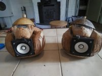
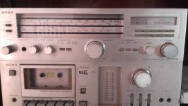
Long story short, a friend of mine gave me a Nikko Alpha II power amplifier that had a scratchy right channel. I figured it would be a great project to learn how to fix up an amplifier. Keep in mind that I have no formal education regarding electronics, and my knowledge of circuits is very, uh, rudimentary.
Here's what I've done to it so far:

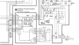
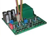
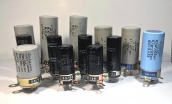
  • Replaced all capacitors on the power supply board and amplifier boards. Several of them on the amp boards were leaking, a couple had leaked quite a bit. I should note that the protection circuit board, the only other board in the amplifier, had already been serviced when I got it.
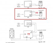
  • Replaced all of the wiring on the main transistors (the ones attached to the heatsink) with jumpers, since the circuit boards they were mounted to were degrading and losing their connection (hence the scratchy left channel)
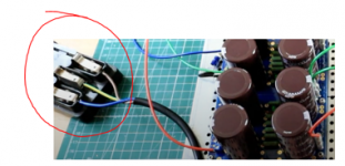
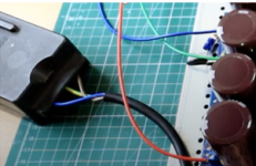
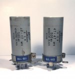
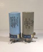
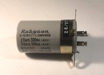
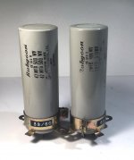
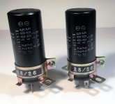
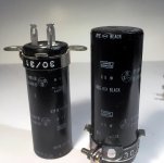
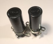
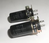
  • Replaced the 4 power capacitors with caps of the same voltage rating and size, to make mounting the new ones into the chassis as easy as possible. The originals were 10,000 uF/63V, the new ones are 22,000 uF/63V.
  • Replaced one capacitor on the protection circuit using jumpers, since it seems to be degrading in the same way as the transistor PCBs with the traces coming loose. (I should note that the amplifier and power supply boards are made of a different, higher quality material and are holding up just fine)
Every fix I've done has usually resulted in me gacking something else up, so the state of the amp has been between one channel muted to the other channel muted to functional--at one point it worked but when I put the chassis and heatsinks back together, a bare wire shorted a one channel and a cap on the protection circuit's PCB trace came loose while I was checking it. The most recent repairs were the power cap replacements and fixing the capacitor on the protection circuit board.


Now, I've turned it on, and hooked it up to my speakers, and it produces music... that sounds like garbled ****. In particular, the midrange and lows mostly sound fine but the treble in both channels is severely clipped and warbled. I've tried this with two different sources, speakers, speaker wires... to the same result.


Interestingly, when I turn the amplifier off... it keeps playing music for maybe 10 seconds, WHICH SOUNDS MOSTLY FINE. The clipping (99%) is gone.


Any idea what I should be looking for? Are the new power caps too much, or did I mis-wire something... maybe something with the transistors again? (Also, if anyone has a website that could ELI5 transistor bias in an amplifier that would be deeply appreciated, most of what google produces goes way over my head). Would it be possible to replace the protection circuit board with something generic that isn't degrading?

Thanks in advance to any and all help!

Faulty Pyramid PA310

I have this pyramid pa310, very good amp. I had replace the 50k potmeters, becuz they were faulty, after playing for some time, the amp goes into protect mode ( the relay clicks out), I have to wait atleast 10hours then I could play it back, but after 10 minutes of playing it clicks out back


I took it to a technician, when I got it back, and turn it on the relay clicks right away without any delay..... and I think he tuned it becuz I'm getting 83watts per channel which it suppose to be ~~~35watts per channel.....


But there is still a problem with the amp when I connect both channel the right channel starts to play very low and distorted but If I Turn it off and and plug out the left side Input, It start to play normal. Same problem applies to the Left side too


I think the technician had changed two Output transistors from the left


Any idea what may be the problem

And any idea of how I could make It have the delay protection when I turn it on 😀


Thanks....

loudspeaker measurement amplifier

Hi there,
I have measured and built a good number of speakers over the past 15 years doing measurements using old amps that I had or found at thrift shops. I am thinking of building a small portable amp to measure and design speakers. I have a couple of questions:

I know that Class AB is typically the recommended type of amp. I believe that Class D (or T) is not recommended due to a floating ground but I may be mistaken and love an explanation regarding this.

Also, if anyone has built a very basic amp just for this purpose, I would love the opportunity to copy your work. I have looked at LM3886 builds and although I think I will try one some day, for now, it seems like overkill for my immediate purpose.

Thanks,
Jay

First project :: XU216/AK4499/OPA1612 :: DAC Pinout & circuit examples

Hi 🙂

I've a bit of experience with Altium Designer, C/PP, general MCU stuff, things like I2C and so on. I'd like to have a crack at making a decent DAC to level up my elec skills. I'm hoping this community could be of help.

I'm at the first hurdle, finding accurate footprints/models to avoid naming 128pins or more. I'm going with the AK4499 to start. Also noteworthy, I'm doing a prototype using TQFP or similar SMD packages to keep things simpler. My first query is, where's all the chip info? I've read the datasheet which is pretty light, very little examples of circuit diagrams/schematics which is a bit surprising but it's at least not the es9038pro hiding behind an NDA. (Great dac though, no hate here) I'm also curious about what the numerous identically named pins are doing like that, no doubt there's method there that I'm missing but either way it's always nice to have clearly labled gpio/input/output/control(i2c etc)/power.

I'm starting to work up the I/V converter section according to the data sheet and I find things a little confusing (on the aforementioned points).

If anyone has thoughts, ideas, examples, anything to kick start a discussion on the topic that'd be great. Even if it doesn't address the points I've made, still all learning is good learning.


Cheers
TIA

Dayton 8" FR PS220 Discussion

This thread is about the Dayton 8" Neo FR driver.

PS220

Which as of this post is now in stock it seems.

The main thing is that this is NOT a DECWARE driver, but a discussion of possible mods and applications seems appropriate.

There is a separate thread on the DECEWARE driver. Here:
DECWARE THREAD

Fwiw, I ordered two just to see for myself... and for fun.

_-_-bear
Projects by fanatics, for fanatics
Get answers and advice for everyone wanting to learn the art of audio.
Join the Community
507,803
Members
7,889,056
Messages

Filter

Forum Statistics

Threads
406,270
Messages
7,889,056
Members
507,803
Latest member
Wynton87