Mutec MC3+ USB external Clock Ref.

Hi! I want to test Mutec MC3+USB performance when synchronized to an external master clock. Mutec sells its fantastic and expensive 10Mhz clock, the Ref10 (now there is also an upgraded version) but in the manual it says that it is possible to use WordClock, Wordclock x256 and 1, 2.5, 5 and 10Mhz as reference. However, in the reclocking section of the manual there is no mention of wordclock x256 as valid reference.

In case anyone knows it, would it be possible to use an 11.2896Mhz or 12.2880Mhz as external master clock also for reclocking?


I have asked Mutec directly but no reply yet.


Best,
JM

tone control by elliott

well ,i am a audio enthusiast and had some difficulty in frequency response of the given circuit ,also providing the pcb layout. would anyone suggest the chnages and modification to have a complete tone response ,say 20 hz to 20khz

Attachments

  • 3384469800_1429246320.jpg
    3384469800_1429246320.jpg
    56.7 KB · Views: 719
  • 4394235700_1429246255.jpg
    4394235700_1429246255.jpg
    44.6 KB · Views: 702
  • 5644535000_1429246290.jpg
    5644535000_1429246290.jpg
    158 KB · Views: 700

Korg AX5G power issue

Hi!

I have a KORG AX5G multi-effect, which worked perfectly until I have accidentally dropped it to the floor. Wasn't a big hit, it fell less from 1 meter and I almost catched it, but it doesn't get any power since, neither from the main power supply, nor from the batteries.

I opened the box and haven't seen any broken parts.

Any idea how to fix this without buying a new one?

Thanks!

Weird situation with Marantz CD-65DX and even stranger solution I found

Just serviced one of these Philips based players (CDM4/11 and TDA1541A), recap (almost complete), cleaning, installed independent regs for TDA and 7220 (opted to not do the NOS here, it's not for me). Also did full adjustment and controlled everything. Turned out there was a smaller clamping issue (sometimes CD made mechanical noises and reading failed, but would play a disc straight when ok), so I tried to adjust the spring for the clamp, this went terribly wrong (never happened before, done this before), as the little pin where it fits on the right side simply broke off!! :O So, I installed the spring on the left side, fortunately Philips probably had foreseen this happening or, in an ideal world, it should have two of these springs, so on the left the CDM clamp and base have the pins. Well, from then on, the refusal to read TOC went worse, about half of the time (even pressed ones! seemed arbitrary, sounded like the laser was trying to read (noisy) and then it failed, the other times it would read well it would make the normal soft and smooth sound). Would play very well when TOC eventually was read, no skips, nothing.
Checked supplies, laser and laser supply - all well. Beautiful eye pattern with 2V-p-p. Even checked real laser current over drive transistor emitter resistor, within normal range. Service routine would be the same too: focussing and everything all straight, but then sometimes failing at step "3".

Then, found out that a little pressure on top of clamp in centre made it fail much less. So, figured it was in fact a mechanical problem.
Tried to change the clamp - no luck here, it's a strange rare format, it's larger than the normal CDM4 which I had as spares.
Tried fiddling around with the springs, nothing changed. Then decided to test without all the clamping, fixing the CD directly to the internal CDM part with bostix (have done this before, it works fine, but sometimes CD decides to fly into space 😀), and beware, it was doing the same thing sometimes! Normally, in some players I had clamping issues, this would isolate the problem.

This got me really puzzled, thought maybe something could be wrong with the lens, radial arm, focus coils, whatever, so I decided to swap the RAFOC only, from a known good CDM4/19 (or at least this is what I tested at the time, it was working!), and to my surprise, the CDM4/19 laser doesn't work in this player!!! 😕 I thought they were all more or less compatible, within the CDM4 series, only changing the motor types (this one has the hall motor, so I couldn't simply swap the whole unit). It wouldn't even focus, and no surprise here, laser voltage was only 11mV with the POT turned to max! WHY???

Took it all out again, swapped the RAFOC again, and then, while testing the original CDM4/11 with a particular CD which would almost never read the TOC (only the internal part, without drawer and clamp), I accidentally pressed the back part of the inner cdm (towards the transformer) DOWN (remember it's suspended on springs, but in this model, it's also secured with rectangular plastic parts which are screwed on at two corners, diagonally), and, how strange, it read the TOC. I maintained my fingers there (so the cdm would be slightly tilted), it would read the TOC everytime! I then tried to press slightly down the other side, too, so it wouldn't be tilted, just lowered, and still, would read the TOC perfectly! So, I installed a few washers between each of the plastic rectangles and the metal bracket of the cdm, so that the path of the spring suspension would be shortened and the cdm effectively was (in an equal way) lowered about one millimeter, but still somewhat suspended. It did the trick!! Mounted back all the rest of the mechanism (thinking that the clamping could make it worse again), but no, still working perfectly!

I've got it testing for some hours right now, hasn't failed TOC once on several different CDs, also CD-Rs, even some difficult discs and scratched, not one skip, too. This is amazing, I can't understand what happened? I mean, this lowered the CDM, yes, but it didn't affect distance to CD from laser, as the motor is on the same part. It might have affected the clamping force, yes, but being more FAR away, shouldn't it have become LOWER now? Remember that before it would help to press slightly on the center (which, btw, would also push the CDM down, so it was the same problem since the beginning, but doesn't seem to have to do with the clamp!). Can it have something to do with the suspension springs?? But why?? Maybe balancing of the RAFOC? I remember once a CDM4/19 which would only work well when the inner cdm part would have two diagonally opposed screws, NOT fitting the other two. Was mounted like this from factory! In a Technics. Maybe that's it? Would love to hear some thoughts on this, to better understand.

Hopefully the player is definitely fixed like this, still have to do further testing, but I found this so strange and odd that I had to share. Also, it might come in handy to some one some day if experiencing something alike.

For the rest, I'm going to test that spare CDM4/19 in another player when I have time, hopefully the fact that it doesn't worked in this player is really due to incompatibility and not ESD-damage, for example...

Obsolete transistor replacements

I am having problems finding genuine 2SA992/2SC1845, 2SA1145/2SC2705, 2SA1306/2SC3298 , and some other ones. I trust ebay as much as a tuna sandwich from a gas station vending machine when it comes to authenticity of merchandise. Unless someone knows a reliable source and would be kind and point me in the right direction.

What do I look for in finding replacements? What is important? What should be prioritized? Ft, Cc, Ic, Vcb, Vce, hFE are some of the perimeters besides that the transistor has to fit on the PCB. I am trying to bring life back to a Sansui B2102 if it matters.


I've spent some time on this now and I don't feel confident in the replacements suggested that I find as most of those are now obsolete as well.

TDA7498 input protection

Hi everyone,

I'm building a guitar amplifier on TDA7498MV with EQ, and have the following problem:
Since the EQ is built on virtual ground with 15 Volts offset, I have to protect the inputs of TDA from transient response(split capacitors charge/discharge on turning on/off).

I'm about to use the circuit as in attached file
attachment.php

and confused about D3, D4 diodes.
If I use usual silicon diodes, the voltage on INN/INP can get lower than -0,3 Volts(absolute maximum ratings from datasheet). Schottky diodes can have leakage current. 5 uA is still acceptable, but I don't know how warm they could be in closed case(for example at 100 celsius their leakage current can get up to 10mA).

Does anyone knows the most suitable solution for such case ?
Thanks in advance

Attachments

  • protect.jpg
    protect.jpg
    81.9 KB · Views: 200

Download Mp3 music from Youtube to your computer

Hello! I was listening to music on Youtube and saw a good song, I wanted to download that song to my computer but I don't know how to do it. I followed the ways on Google instructions but still with no success.
Can you guide me if you know how to download Mp3 music from Youtube to your computer? Thanks for reading the article !!!

- alle achtung marie klingelton -

  • Locked
Korg NuTube B1 guide

SNEAK PREVIEW. Not yet complete (getting closer though)

Add wiring diagrams


Korg Nutube B1 assembly guide

Nelson Pass' original article - http://www.firstwatt.com/pdf/art_diy_nutube_preamp.pdf

NuTube website - Nutube – English | korgnutube.com – English

Pete Millett's NuTube US website - NuTube


Please read though the entire guide before starting.

If the photos are very big now, reload the page and the forum software should resize them. You can then click into them for proper aspect ratio, and then click into the expand button in the lower left to make them very large.


Neatness counts!! 🙂

CHASSIS MECHANICAL AND WIRING


IMG_2476.jpg


Gather these parts.

(Well, you don't actually need the knob right now... 🙂 )

Note that the toggle switches are identical.

IMG_2477.jpg


IMG_2478.jpg


IMG_2479.jpg


The bottom panel has the 4 holes drilled for the PCB standoffs


IMG_2481.jpg

Insert the nuts into the channel


IMG_2483.jpg

Slide the nuts under the holes then attach the screws

IMG_2484.jpg


Make sure the holes are aligned with the threaded part of the aluminum extrusion, not the square channel where the nuts go.

IMG_2485.jpg


IMG_2488.jpg


Back panel

IMG_2490.jpg

Barrel jack assembly

IMG_2491.jpg


IMG_2492.jpg


RCA assembly

IMG_2493.jpg


Place the shoulder washer here as shown

IMG_2494.jpg


IMG_2496.jpg


Align tabs as shown

IMG_2497.jpg


Power switch wiring

IMG_2503.jpg


Make the leads long now and trim them to size later.

IMG_2498.jpg


Begin with the LED


IMG_2499.jpg


Bend the LED 90deg around the curve of a screwdriver. Long leg on top.

IMG_2500.jpg


Wires as shown

IMG_2501.jpg


LED and resistor as shown. Making a couple of bends where the LED attaches to the switch will greatly aid assembly.

IMG_2505.jpg


IMG_2504.jpg


IMG_2506.jpg


korg%20power.jpg


SELECTOR SWITCH WIRING


IMG_2511.jpg


It's easier to make the wires long now and trim to size when soldering.

Please note that you don't have to follow my color scheme, but if you do checking things will be much easier...

For that matter you can substitute other wire if you like. It's DIY, after all. 😎

IMG_2507.jpg


Solid colors on the left, white traces on the right. Begin with orange on the bottom.

Note that there is no "top" or "bottom" to the switch until you attach things to it.

IMG_2508.jpg


Brown in the middle, this will go to the potentiometer


IMG_2509.jpg


Blue on top.

(Shameless plug: the Fire-Metall solder is absolutely the nicest I have ever used. )

IMG_2510.jpg


Complete. Mount into front panel as the power switch.


IMG_2513.jpg


Potentiometer breakout board

IMG_2514.jpg


IMG_2515.jpg


A little tape helps keep everything in place when soldering the PCB

IMG_2516.jpg


IMG_2517.jpg


The screw terminals mount as shown if you want to use them.

FRONT PANEL MECHANICAL AND WIRING


IMG_2518.jpg


IMG_2519.jpg


IMG_2520.jpg


IMG_2521.jpg


IMG_2522.jpg


IMG_2523.jpg


IMG_2524.JPG


The screws go the threaded section, not the channel where the nuts are.

IMG_2525.jpg


Hopefully you can get your chrome nut on the switches better aligned than this. 😀

IMG_2526.jpg


Front panel should look like this now.

General Design Question - Amplifiers vs Distortion Pedals

Hi Folks,


I'm currently putting together a passive summing mixer for use in my modest home studio. I thought it would be good if I added some sort of make-up gain stage to bring the output of the mixer up to something like line level.


Ideally I'd like the gain stage to be relatively clean up until, say, 80% of its maximum, with the last 20% introducing some subtle distortion.


I realise that there are a lot of different ways that this can be done - amplifier stages (Neve BA340), op amps (API 2520), older amplifier designs like the ETI 340, etc. This led me to "light" overdrive pedals like the Mona Lisa.


So what I'm not clear about is the difference between an overdrive pedal design and an amplifier design. Is the overdrive essentially an amplifier running at its limits and then having its output reduced? Is that the basic idea?


Would it be possible to modify something like the Mona Lisa so that it kept its distortion characteristics and at the same time acted as an amplifier?


I realise that this is a vague design question but it's something that I'm not clear about.


Cheers,


Chris

  • Locked
Korg Nutube B1 Pre-Order Q&A

The intention of this thread is to allow the main thread to stay on topic about the project itself, without getting diluted by pre-order questions. The store helpdesk will watch this thread but not the main Korg Nutube B1 thread.

Where to ask your question:

  • General questions about the pre-order process, kit composition, etc: right here!
  • Non-technical assistance with your pre-order: email the store helpdesk
  • All technical discussion not specific to the pre-order itself: Korg Nutube B1 thread

Project Links

Pre-order Links

High permeability soft magnetic powder

Hi folks,

I need this stuff to fill between air gap due to poor technical cutting of c-cores to restore permeability. I'm winding an input transformer where I need to best of permeability from a nanocrystalline c-core.

Now I'm using 99.95% Iron powder from Merck which increases my permeability to 1.5 times, but it is not enough.

Where could I find something fancy like permalloy, iron-cobalt powder or iron powder annealed in hydrogen?

I could buy a cobalt-amorphous toroidal core and try grinding it down to powder, but that would probably destroy the permeability.

XLR microphone adapter circuit board connector

Hi. Not sure it this is the right place for this.

I have a new 'I can't afford to replace' $500 Canon microphone adapter (MA-400) that needs a part. A separate company makes a wireless receiver that when plugged into the XLR input, permanently locks on, blocking the release switch.

I pulled it all apart and found the XLR female receiver tubes were silver soldered to the board. Unfortunately, one broke free when removing the XLR connector from the circuit board.

I dare not solder it back because the pin that secures it is still embedded in the circuit board. Any idea where this part (the small one in pic) can be bought?

An externally hosted image should be here but it was not working when we last tested it.

2 Hypex nc500oem amp modules, 2 hypex nc500 oem input boards, 2 hypex smps1200

2 never used Hypex nc500oem modules, 2 never used Hypex nc500oem input boards, and 1 Hypex smps1200 power supply. Just put in a box, add wiring and jacks, and your set! $1000US OBO.

Also have a second SMPS1200, never used, if you want to go dual supplies. $200US OBO.

Buyer pays shipping from US. Paypal for payment. Thanks!

Attachments

  • nc500oem with power supply.jpg
    nc500oem with power supply.jpg
    520.7 KB · Views: 511

8 channel R2R Dac

I have the following components available which I bought to construct an 8 channel dac. Plans have changed....

(4) Soekris dam1021 0.1% resistor dac boards. New, never used. These were upgraded by Soekris to a later rev.

(1) SSR03 Sjöström Super Regulator Power Supply, Built. New, unused.

(1) Exa U21 8 channel usb to i2s input board

I paid around $1800+ for the above. Looking for $1200US. Buy pays shipping.

Do not want to split up at this point. Thanks.

I also have 6 hypex nc400 ncore amp modules, new, unused. Paid around $2000US for all, would like to get $1500US for these. Do not want to split up at this point.

Anthem Integrated 1; blew EL84 and took resistor

Hello All,

My brother has an Anthem Integrated 1. The amp had been retubed back in April or so with JJel84's and various brands for the rest. Recently the amp had one of the EL84's blow and it took a nearby resistor with it.

Is there anything other than the EL84 and resistor that I should replace or be concerned about? I have attached some photos. Thanks in advance for any suggestions/help.

Thanks,
Dan

Attachments

  • anthem1.jpg
    anthem1.jpg
    107.6 KB · Views: 202
  • anthem1b.jpg
    anthem1b.jpg
    131 KB · Views: 217

How to control my plate amp

So I have an old 5.1 plate amplifier from back in the day. It's a genesis media labs g506 (white van scam). It actually isn't a terrible amp so I decided that I'm just going to buy a cheap dts decoder and try to use it. The only issue I'm having is that I no longer have the lcd board. Everything else is there besides that. What can I do in this kind of situation?

S.E. bootstrapping: pros and cons

Hello, I would like to test this config (see R17 to cathode resistor, instead of to ground)

I notice on .op simulation that the tube is biased much hotter, the frequency response is better on the bass and that reduces the load of the driver stage.

But I don't know which could be the real pros and cons of bootstrapping, if you can enlight me.:scratch2: 
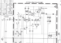
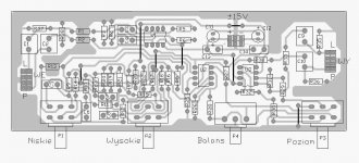
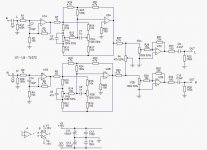
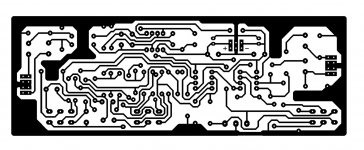
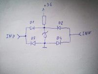
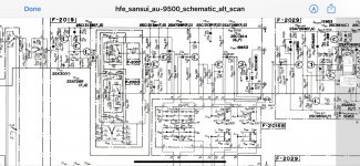
as I don't see schematics with this config.
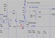
Thanks

Attachments

  • bootstrapping.jpg
    bootstrapping.jpg
    81.9 KB · Views: 226

Teaching young people how to listen to stereo Hi-Fi

It is only in the last few years, since our home stereo broke and could not be repaired, that I have really begun to listen to music, and hear music, and experience stereo from speakers (not headphones).

I am now over 50, and the reason for revealing my age is simply that I wish I had learned to listen to music on speakers many many years ago, my enjoyment would have been so much greater. It was only cassette tapes, but my parents did purchase a Hi-Fi rack system with mini refrigerator speakers in the 1980s and we had it for about four years, in which I simply played it loud.

I will say more later, and post some pictures.
  • Like
Reactions: Sscov

BEGINNER!! Need help understanding Crossover/Impedance/Wattage

I just built my very first speaker with the little knowledge I gathered from YouTube and research on different sites, but I'm still having trouble answering a few questions in regards to what power amp to use, and how the crossover's I purchased affect wattage and impedance.


I built mostly based on design, and that I just wanted to give it a try, so if my design and or choices for hardware are way off, that's why (and also why I'm writing this, so I can learn for next time).


Consists of .....


2 2-way speakers (w/3" Peerless PLS 75F25AL04 [8 ohm] and 4" Dayton Audio PC105-8 [8 ohm])


Peerless
8 ohm, 15wRMS/30wMAX, 100Hz-20kHz
Dayton Audio
8 ohm, 40wRMS/80wMAX, 80Hz-15kHz


Crossovers are DROK 2-way
150W, 4-8 ohms, 12db/oct on high and low frequency, 3200 Hz split
Amazon.com: DROK 150W Bass Treble Dual Channel Audio Frequency Divider Distributer, 4-8 Ohm 2-Way Crossover Filter for Subwoofer Hifi Speaker: Car Electronics

Amp is DROK 2 channel 50W digital amplifier
Amazon.com: DROK 50W+50W Dual Channel Stereo Amplifier, DC 9-24V 12V Mini Bluetooth 4.0 Audio Amplifier Car Home, HIFI Audio Receiver Amp Ampli Module with US-type Power Supply Adapter, Built-in EMI Filter: Home Audio & Theater


Here are my questions .....


Power - How is wattage calculated going through a crossover? Are the speakers split between the two channels going through the crossover? (meaning is the 15W and 40W added up = 55W then split in two to roughly 27W?) Or is the power I need the total 55W at what impedance? Also, what does the 150W rating on my crossover mean?


Impedance - How does the crossover affect impedance? I have two 8 ohm speakers, so does that make the impedance going through the crossover go down to 4, and therefore 4 ohm load needed from my amp?


I know, you're thinking this info is easily found on the internet, but for some reason every search I entered did not answer these questions. A little help is greatly appreciated!!! Thanks in advance from a new DIY Audio member.


-sdbarnold

OT - Laptop Trackpad - Arrggh!

Why do they have to make the trackpad on modern laptops have a bazillion functions when x-y is all I really want? The buttons seem to be integrated with the pad surface; I cant click left-mouse / right mouse w/o the pointer moving OFF what I'm trying to click on.

And then I somehow enter into this "single finger screen zoom" mode - something that if it never happens again, I'd be more than delighted! I cant even figure out how I make it do this - much less how to turn it off - forever. Seems like it just does it at random...

This seems to be a standard feature of two laptops I've owned over the last few years. On the latest Dell Latitude 3570, I can mitigate some of it's ridiculous over sensitivity using Windows controls. But if I boot Linux from a USB, the "standard configuration" is back to crazy making "lets cram 10 different functions into 2 buttons and a 12 sq in surface - and make the pad so sensitive you can move the pointer around with just your willpower".

I want X / Y track - as in pad. Left Mouse - without any pointer movement influence. Right Mouse - without any pointer movement. Period. I cant even input the "/" above - as a correction - without somehow "accidently" highlighting the entire paragraph above it!

If anyone knows how to do this via OS or Bios settings I'd be much appreciative! Thanks so much - (I have a BT mouse...as one fix which really is just a desktop fix)

Using a transducer as a headphone subwoofer substitute

(not sure if this belongs in the subwoofer or headphone section -- seemed like it would be of more interest to the headphone crowd!)

Hey guys, just wanted to post about a fun experiment I just tried: using a bass transducer as a subwoofer substitute for my headphones 😱

NjIpQMG.jpg


I lie down and set the transducer on my chest, then cross my arms over it to give it a bit of weight and couple the bass into my rib cage.

Not exactly what I would call high fidelity, but it is certainly a lot of fun 😀

The transducer is an AuraSound AST-2B-4, available on amazon for about $60. The amp is an eBay cheapie (about $15), just search for TDA7498.

Pop-free startup/shutdown

Ok im trying to get my head round how to ensure my speakers are safe, using my new diy amp.

Setup is as follows: 2x tpa3255 evm boards, signal from minidsp 2x4HD bare board in same case. All powered by one connex smps 800w psu.

Obviously with one psu and a traditional "kill the mains" power switch, i cannot easily do a startup/shutdown sequence, or use the "reset" jumper on the 3255 boards. How do other people deal with this issue? I cant be dealing with multiple on/off switches and a specific "sequence" its gotta be kid, and powercut proof.

I also need something simple, budget is finished, and there is barely any space left in the box!

When is an In-Wall Speaker In-Wall?

Experimenting with a CBT column speaker to reduce hard floor reflections in a center channel. Allen B and others have mentioned in-wall speaker placement = boundary advantages.

My question: when is a speaker "in-wall"?

In this case, the speaker baffle is five inches off the wall. Does that mean the speaker is in-wall for frequencies longer that 5 inches long (~ 2700Hz)?

Attachments

  • IMG_20201012_134640252.jpg
    IMG_20201012_134640252.jpg
    514.6 KB · Views: 161

NAD C356BEE Repair and adjustment question

I bought a NAD C356BEE amplifier a few days ago.
Symptoms as described by seller: "No sound, but will power up. A friend did some repair but it still doesn't work."
🙂
When I had a look at the amp, the +/- 55V rails were OK but the -26V and -18V rails were not- just a few tenths of a volt.


I had read this thread:
NAD Amp Repair (Newbie) which had a link to the service manual for the amp. Thanks!
http://www.bluefoxnet.com/files/c_356bee.pdf

I looked at the supply circuit and measured some voltages and ordered some parts for wwhat I assumed was the regulator circuit for the -26 and -18 rails.
See pic below.

Attachments

  • supply circuit marked.jpg
    supply circuit marked.jpg
    59.7 KB · Views: 628

Newbie needs patient advice on cleaning NAD receiver

I have an NAD 7140 receiver. When trying to clean the pots and switches, they are obscured by boards above and below. The bottom appears to have about 10 connections screwed to a cross bar. It looks there is some type of white sealant or insulation underneath each connection. May I safely unscrew those to allow the board to shift enough to reach the pots?

Oda wood planar speakers

Just came across the Oda wood planar speaker project which aside from being a speaker is a platform offering exclusive artist streams. See here:

Oda - Live Performances in Your Home

and here:

The Quietus | Features | Oda To Joy: The Stereo System Bringing Terry Riley To Your Living Room

I wonder how these speakers are supposed to work. The website is low in details. Anybody an idea?

The complete Okeh and Brunswick

For Sale: The complete Okeh and Brunswick Bix Beiderbecke, Frank Trumbauer and Jack Teagarden Sessions (1924-36)


I purchased this set new. Only the first of the four disks have been opened and listened to. Disks 2, 3, and 4 are still factory sealed. The set is next to new condition. The accompanying booklet is in perfect condition.


$100.00 shipped in US. Paypal. Thanks.

Attachments

  • IMG_1496.jpg
    IMG_1496.jpg
    318.4 KB · Views: 117
  • IMG_1497.jpg
    IMG_1497.jpg
    373.8 KB · Views: 112
  • IMG_1498.jpg
    IMG_1498.jpg
    314.1 KB · Views: 112

Suggestions for a high efficiency 10” (sub)woofer?

Looking for suggestions on a 10 inch professional (sub)woofer that’s efficient (90-95dB) and has a low Fres (30-45Hz), while also having a high Qms and low Qts as well as a low Vas. This driver will be used as a woofer in a 3-way, crossing at about 200-300Hz.

I know this is asking for a lot, but I found a couple of candidates like the Eminence Kappa Pro 10LF, the Sica 10SR2.5CP and possibly the Beyma 10G40. If you have any suggestions I’d love to read them!

Attachments

  • 2D30EF07-6CB6-4C4A-9BD2-0049C228755A.jpeg
    2D30EF07-6CB6-4C4A-9BD2-0049C228755A.jpeg
    28.9 KB · Views: 355

Robert Plant Concert T-Shirt

For Sale: Robert Plant Concert T-Shirt


I am the original purchaser of this shirt. It has never been worn or washed and has spent the last 32 years stored with my other event t-shirts.


I attended the Robert Plant Concert in Chicago Illinois, USA at Popular Creek Music Center on May 29, 1988. I loved that place but it’s gone now. My memories are of starving for something Led Zep and I had pretty good seats just about center of the stage about 12 rows back.


The shirt is original Licensed Product from the tour and in unworn condition. Please note the “moonlight ltd” which produced the official t-shirts.

Size large. As new. Never worn.


$100.00 shipped in US. PayPal only. Thanks for looking.

Attachments

  • IMG_1424.jpg
    IMG_1424.jpg
    384 KB · Views: 154
  • IMG_1425.jpg
    IMG_1425.jpg
    687 KB · Views: 149
  • IMG_1426.jpg
    IMG_1426.jpg
    351.3 KB · Views: 144
  • IMG_1427.jpg
    IMG_1427.jpg
    441.6 KB · Views: 138

For Sale: Jimmy Page and Robert Plant Concert T-Shirt

For Sale: Jimmy Page and Robert Plant Concert T-Shirt


I am the original purchaser of this shirt. I attended the Jimmy Page and Robert Plant Concert at the Rosemont Horizon in April of 1995 in Chicago Illinois

USA. Not sure what show it was but either it was the 28th or 29th of April 1995.


This is the authentic t-shirt from that show. It has never been worn, still has the original tag attached, and has been stored away with my other event t-shirts. Please note the pictures of the waist (bottom) of the front of the shirt both front and back with has the “winterland 95” logo printed into the design of the shirt which is the company that produced the officially licensed products.


Check this link for show dates: Jimmy Page & Robert Plant Concert Map by year: 1995 | setlist.fm


Size large. As new. Never worn.


$100.00 shipped in US. PayPal only. Thanks for looking.

Attachments

  • IMG_1418.jpg
    IMG_1418.jpg
    430 KB · Views: 171
  • IMG_1420.jpg
    IMG_1420.jpg
    448.9 KB · Views: 166
  • IMG_1421.jpg
    IMG_1421.jpg
    416.7 KB · Views: 160
  • IMG_1422.jpg
    IMG_1422.jpg
    426.1 KB · Views: 170
  • IMG_1419.jpg
    IMG_1419.jpg
    478.4 KB · Views: 164
  • IMG_1423.jpg
    IMG_1423.jpg
    463 KB · Views: 87

Need to replace 2SK30A on tone board of Sansui AU-9500, 2SK170???

I have a Sansui AU-9500 that I’ve done some work on. I replaced all of the electrolytics, relay, bias and offset trimmers, and replaced all of the 2SA726 and 2SC1313s with KSA992 and KSC1845s.

There is a VERY intermittent issue in the right channel where it all of a sudden gets a lot of crackles and pops and it can get kind of loud and then go away for a little while until it comes back again. It’s very annoying. By swapping the preout/main in cables I found the issue was in the preamp section. The popping is not affected by the volume control, that and by swapping the input wires on the tone board has gotten the issue isolated to the tone control board itself. Looking at the schematic the only thing between the volume pot and the preout is the tone control. I’ve tried using freeze spray to isolate the issue with no success. The issue really seems like a transistor issue and the only four transistors on the board that weren’t replaced were a pair of 2SC1364 and a pair of 2SK30A. I replaced the 2SC1364 with a pair of KSA1815. After that I thought I had repaired it as it was issue free for over a full day of playback.

Unfortunately it’s making the noise again. It doesn’t make the noise long enough to use a scope to try to find it. The only other transistors on the board is the 2SK30A. One was replaced in the past and it happens to be in the right channel, the channel with the issue. It was replaced with a GE FET-1.

I happen to have some 2SK170s on hand. I haven’t done a lot of matching fets, not as much and your regular transistors that is, but it seems to be over qualified for the job. Would the 2SK170 make a decent replacement?

There is a filter switch board that interacts with the tone board, but it just has resistors, polyester caps and the switches which were cleaned. The noise doesn’t go away when I flip the switches.

Any other ideas on what the issue could be?with it being so intermittent is making this a nightmare.


PS, thought I should add that I held my iron to the fet in the right channel and it didn’t seem to make it faulty, but not sure if that means anything since freeze spray isn’t able to eliminate the issue.
Dan

Attachments

  • CC958FD4-6239-4FFE-9F3F-4E9C348E2FC1.jpg
    CC958FD4-6239-4FFE-9F3F-4E9C348E2FC1.jpg
    1,022.1 KB · Views: 734
  • 5C7EE131-8983-4F70-BA40-3F6FA0A0AAFE.jpg
    5C7EE131-8983-4F70-BA40-3F6FA0A0AAFE.jpg
    429.7 KB · Views: 805

Parafeed SE 300b amp on the cheap.

As an exercise in using up parts on the shelf, I'm considering a 300b SE amp in parafeed. I'm not saying this will be optimised in any way, just that hopefully it might work moderately well. I'm sure many of you have redundant PP OPTs in cupboards, so it's a theoretical choice. Mine are 6.6K.

Thinking of a parafeed choke, my eyes fell on four 157G Hammond chokes, 30H and 40mA. These could be used in series for 60H at 40mA or in parallel for 15H at 80mA. I've tried a single one with driver tubes and the sound is pretty OK - it's used in the Hagerman Tuba. Various other Hammond possibilities. I also have some 10H at 100mA which could be used in series for 20H at 100mA. A proper choke would be better of course, but that would be where the costs would start to rise.

Again, the PP OPT isn't optimised and a proper one would be a lot more expensive.

Any fans of trying out a "300b SE parafeed on the cheap" or am I being a bit fanciful here? I've tried a parafeed headphone amp which was nice and used a 157G and a Lundahl LL1689/PP OPT, but not a 300b SE. I'm open to the idea of a 2a3 version as well.

Audio Transformer for reverb spring in OrganMate

Hi,

I am trying to rebuild an OrganMate reverb unit, which is designed for use with Hammond Organs. Can anybody tell me what kind of audio transformer is used here? In the schematic someone noted the d.c. resistances of the transformer and the reverb spring. But I guess that does not help so much.

Schematic: https://www.tonewheel.com/Schematics/Organmate.pdf

Greetings Christian

Stetsom EX8k

Hello.

I bought stetsom ex8000eq(1ohm) with a blown ps section. It had water damage, ps fets had pretty heavy oxydation between all 3 legs and probably gate turned fully on and blew the fets(most drain/source legs were melted).
I put new irf1404 in because i had enough of them laying around and the amp came back to life but still has some problems. I didnt notice main problem on the first day because with small bench supply it seemed normal that amp wont turn on with first remote signal.
With further testing i understood that when applying remote with rail caps dropped to 0V(actually anything below 7V in rails) then the amp goes into protect and flashes red once(means overload or short in the output) but applying remote second time will always turn the amp on. So anything above 7V and amp will turn on right away.

Second problem is when unplugging remote theres a weird noise/sound in the output and speaker is slightly sucked in. On the scope you could see something close to sinewave at the output right after the remote is removed and its present on both "channels".
Both problems are still present either having speaker connected or not.
I have desoldered all the the IC's and drivers incase there is oxydation underneith or something and everything looks perfect. All the voltage regulators test fine. All the drive signals on both sides of the amp are identical and same goes with ps section. I didnt change ps drivers because i saw no need for that at the time.
Leaving these problems aside amp works well, it has played a few hours on workbench and i put in car for about 15 minutes to get some heavier stress on it and it works just fine. One thing that looks weird to me is that output inductors get hotter that i'm used to. After 10mins or so they are quite untouchable for hand(both inductors a equally warm/hot and output caps all read fine.

If anyone has some advice or what to check next your input is appreciated.
Thanks in advance.

Bus pumping

It's come to my attention that I have to solve the bus pumping problem on my IRS2092 amp. I have 4 x IRS2092 L15DSMD boards. 2 for each speaker in bi-amping. All 4 on 1 SMPS.

I have read that 2 solutions can be either very big capacitance after the PSU. I have 2x 63V Elna's 10000uF in my drawer. Can I use these? Its a double voltage 55V PSU. If I put one in parallel (55V+ to GND and 55V- to GND) on each rail would this not create a short?

The other solution is phase inversion? What is the easiest way to invert the phase on the 2 left channel boards? My DAC actually has balanced output converted to phono? Does this make phase inversion easier if I put XLR inputs in my amp chassis (drawings pleeeease....)

FS: Accuton C173-6-090 and S220-6-222 Neodymium Drivers

FS: Accuton C173-6-090 and C220-6-222 Neodymium Drivers

I have three each of Accuton C173-6-090 (6.5 inch ceramic mid/bass) and C220-6-222 (8 inch ceramic woofer) with neodymium magnets. All purchased in 2014. The C173s where lightly used for about 3-4 months. The C220s never installed. All in excellent condition with original boxes. PM me and I'll send you a link to photos.

Simple DLNA Renderer for Odroid C1+...or not?

Hello,

I'm Oliver from Germany and it's my first post.

First of all please be patient if I don't succeed in getting to the point. I'm a "digital audiophile" and my perfect setting for listening music is:

[NAS] ---USB A-B---> [AMP]

Basically this works fine and is the straightest signal way from NAS (Synology DS716+II) to amp which is capable to handle digital audio files up to DSD256 (Audiolab M-One). Server app is "Synology Audio Station", transcoding disabled, bitperfect and gapless playback.

The problem: after an indefinite period of time (sometimes on from beginning) the amp looses input signal and I have to pull the USB plug once to reactivate the connection.

A solution: runeaudio on Odroid C1+ with network source ...as a kind of "technical middleware" and it keeps up connection. 😉

Well, runeaudios library gui is quite nice and clean but DS Audio is a little more comfortable.

A solution is to activate UPNP/DLNA in runeaudio.

[NAS] ---RJ45 (DLNA)---> [runeaudio] ---USB A-B---> [amp]

Works, too. Problem: no gapless playback using Audio Station/DS Audio (iOS)

I have no idea about Linux but I've heard something about a lightweight distribution with MPD and upmpdcli - instead of runeaudio ('oversized') - could be a solution. Could it?

If everything is too complicated, I'll stick with runeaudio as a player.

———————-
edit
———————-

I just used Volumio for comparison, no improvement here either so I think it won’t work with other linux MPD solutions. Am I right? Any other ideas?

Regards,
Oliver

Things to consider JBL 2226H + Faital 6FE100 + B&C DE250

Hi,

I am planning a speaker for home theater use in a small room using the JBL 2226H, using a 3E Audio ADAU1701 as active crossover (or maybe a chinese ADAU 1452).

Already have the JBL woofers, the horn (QSC H152i clone) and the B&C DE250, and I have a couple of Faital 6FE100 6.5" woofers laying around that I could use...

Keep in mind these speakers will be used as left and right channel, and I am almost decided that I will go sealed, in a smallish cabinet, aiming for an extension 50hz+, as I already have 2x 15" subwoofers to take the work from there.

I do not aim for 110db+ just a nice sounding speaker, with nice dynamics and presence.

So the thing is, should I go for a 2-way or a 3-way? Any special thing to consider that cannot be solved afterwards with a ton of measurements and active crossover?

I have build several DIY speakers, modified a few, but never designed one from the ground, thats why I am starting with an active XO (things easier to implement), but I know designing a 2-way is hard and a 3-way is way harder, but I think the Faital would give me a nice meeting point with the 15" at around 800hz and with the CD around 1.5-1.8khz; I will loose a ton of possible power usage, but as I said I am not aiming for high sound pressure.

Looking forward to your opinion

Cheers!

Burson Supreme Sound Opamp V5 experience

Now I was snoopy and ordered a pair of the new Burson Supreme Sound Opamp V5 S for my headphone amp WNA MKII.
Before I used OPA627 (after a lot of others) with best performance.
First short hearing test, my feeling the Supreme Sound Opamp V5 S surpassing the OPA627 in details of music.
In Ray-Brown-Summerwinds - Li'l darling (tr. 3) I hear each hair of the brushes more than with other OPAs.

Its hard to compare them, I don't have two ident WNA MKII, so I need to swap the OPAs for comparing.
The headphones I used for comparing AKG K812 Pro, AKG 712 Pro.

I think, the Burson Supreme Sound Opamp V5 (single or dual) are a very good option to replace OPAs.
The only drawback, it must be place enough.
I must use an additional DIP socket between.

What your experience about them?

About my WNA MKII
New! WNA MKll Head-amp kit.
New! WNA MKll Head-amp kit. - Page 51
The Opamp thread - Page 346

About Burson Supreme Sound Opamp V5 S
Supreme Sound Australia – Supreme Sound Opamp V5
Burson Audio – Supreme Sound Opamp V5
Supreme Sound Australia – DIY_Audio_Project
Burson Audio – Supreme Sound Opamp V5
https://www.youtube.com/watch?v=j6s88jANfCw&feature=youtu.be

Mosfets extended off the board via daughterboard...ok?

I was looking around online while I wait for some new parts to arrive and saw an amp kit that came with little daughterboard type things so you could screw the mosfet to a more convenient or efficient place on the heatsink than where it may sit on the main PCB.

I think I could make use of this idea in my curernt build, as all the chips on mine are currently in the front half of the heatsink.

Is this a good idea and what kind of additional problmes could it bring to a noob like me

ESL57 conductive coating on the treble panel

I am trying to get a resistance reading off the treble panel stators but can only get a reading close to the wire connection rivet. I try further up the panel but no matter how I try... no reading. Same for the mid-range section of the stator. Getting a reading off the bass panels was no problem as pushing the meter probes through the grey paint is easy and needs little force. Not so with the treble. Has anyone else had similar problems or am I doing something not right. I can't find any info from any posts. I want to get this right as I have a couple of small arced areas that need repairing and dont want to jeopodise the great results I've had with the bass panels so far.

Help required on Logitech Z-2300 toroidal transformer

Hi, i am a newbie in this forum, and require help on my Logitech Z-2300 2.1 multimedia speaker system. My Z-2300 toroidal transformer have died and i need a replacement. But i do not know the VA rating of this transformer.

I opened my Z-2300 subwoofer and clicked some pictures, which i am posting below:

Toroidal Transformer
An externally hosted image should be here but it was not working when we last tested it.


Z-2300 slow blow fuse rating
An externally hosted image should be here but it was not working when we last tested it.


Input voltage from the wall
An externally hosted image should be here but it was not working when we last tested it.


I was also able to gather the following information from the net:

Transformer Details
Manufacturer: Ten Pao International Ltd.
Model No: TOG433028F0
Input: AC 230V/50Hz
Output: AC 20.1V x 2
Diameter: 9.5 cm;
Height: 4.5 cm.
Amperage: Unknown

Also i want to change my capacitors from CapXon which are know for bulging & exploding. Which company capacitor should i use? Will a even higher farad value give an even better result?

Capacitors
An externally hosted image should be here but it was not working when we last tested it.


An externally hosted image should be here but it was not working when we last tested it.

omni mic and dats v.2 and driver.

Price dropped on omni mic v.2 and dats ver. 3. And dsp.

Good Afternoon Everyone. I am selling the following because our wood shop is closed and some family is moving out of state and The following Items are not going to be used now for our speaker projects. Feel Free to E-mail me or p.m. Me with questions or for pictures. Please no low ball offers. If you want a few things I can come down on the price. The more you buy the better the deal.

Please Make offers and I will go from there.


1. Dayton Audio Omni Mic V 2 Brand new never even used. Took out of package to inspect. Sold


2. Dayton Audio Dats V. 2 Out of packed and never used just zip tied to a piece of wood to hold in place. ( Comes with disc ).
Sold.

3. Mini Dsp 4x2 HD DAC Version New never used just mounted to a board I was going to use. Sold.


4. Mini Dsp Mic MK1 New never used.


5. Dayton Audio Dsp rca to b port 44khz. Never used just tied down to a board. Sold.
.


6. Dayton Audio PS95-8 Full range drivers. New never used.
Sold.


7. Audio Nirvana Super Horn 3 speakers a pair. New never used.
Sold.

8. Lil Audio 3 full range drivers tested but, never used.
(Got them of amazon). They are Metal driver's.
Sold


9. Dayton Audio PS65LP-4 6 1/2 Full range drivers. Never used. New


10.Pyle 2 channel Amp CS 400. Has been cleaned inside and out and when plugged in fan and both light for both channels light up. I have no other way of testing it. It weights 50 pounds so local pick up would be nice. Buy pays shipping.


I have all the boxes and paper work and packaging. Something might have a little scratch on the bottom but, never used. Not the drivers. The mics are not scratched. Bottom of the dats or mini dsp or dayton Audio dsp.

I am willing to package and ship. Buyer pay's shipping. I will only Ship with in the 48 United States. Thanks Jeff

VU Meter Replacement

Hey Gang,
First, allow me to thank you for your time in reading my question!

Ok, I recently put into service a Yamaha MR1642 console. To my surprise, only 1 of 6 VU meters work. The only one working is fine...the other 5...are pegged over the red to the right and not moving.

So, my question, are these just "stuck" or do they need replaced?

All levels are within normal limits, just in case you would suggest the levels are screaming hot. LOL

Well, again, I wish to thank you for your time.

Pamela Lee
X Rock Radio
Radio Station - X Rock Radio

Active cardioid build and questions

I have some questions regarding active cardioid speakers like Kii 3 as I'm considering building my own simpler version for the fun of it.

I have a minidsp 2x4 HD and will use passive crossover for the mid-woofer to the tweeter in waveguide so CD will be taken care of by the waveguide above say 1.5-2k. Amp channel 1 for mid/tweeter and amp channel for the cancellation drivers. Active cardioid between 100hz - 1.5-2khz is the aim

Box will be sealed with separate compartments for the main drivers to avoid interaction between them inside the enclosure

Question are as follows:

1. Is minidsp HD able to achieve this with the standard PEQ or do I need FIR?
2. Are side mounted drivers better then a rear mounted driver for the cardioid cancellation?
3. Are there any tricks /traps that I should be aware of?
4. Any other thoughts on the concept above?

Thanks

Attachments

  • cardiod concept.jpg
    cardiod concept.jpg
    380.1 KB · Views: 179

raising transformer va

Hi Thanks for reading.

Just saw a video where a woman claimed to raise the va of a transformer by removing the secondary windings of the transformer and replaced with much thicker enamled copper cable.
Is it that simple to raise transformer va? Simply count the number of secondary windings, replace with thicker cable, measure with voltmeter to make sure the voltage is correct?
Thanks

pioneer deq 9200

hi everyone, so i have a pioneer deq 9200 that had lots of leaky caps one super cap that pretty much spewed its insides on the board. A trace that runs right behind it was gone so i replaced caps plus super cap the dsp now works powers up plays but the spectrum analyzer is not working, meaning the lights are not dancing when playing music. The first 5 rows from left to right are all on permanently. Without schematic or some direction im affraid im at a loss. any help is greatly appreciated

Teenage Engineering OB-4

Hello Everyone,

Every so often I check the Teenage Engineering site for new products. You can say what you want about the company, but one thing they are is creative and have well designed thought out products.

Anyways, they have a new radio called the OB-4. It doesn't seem to be released yet it is a typical unconventional product. They price is quite high, but it is like no other radio I have seen. It is short on specs (I can't find what the woofer and tweeter used). Would be interesting to hear.

OB–4 magic radio

It almost seems to want to be a radio and a musical instrument at the same time. Anyways, perhaps some may be interested and get some inspiration from it.

yatr

85 ohm RCA cable matched with 75 ohm or 50 BNC connectors?

I bought several meters of RCA cable to use as an unbalanced interconnect and am now contemplating matching it with BNC connectors, i.e. from Canare.

Other forum users have praised BNC over Chinch due to the good locking connection and since I am building my stereo by myself, I do not need to use Chinch.

Do you think this is a good idea or should I stick to RCA/Chinch connectors?:scratch1:


If going down the BNC route, which resistance should the BNC connectors have? Canare only has 75 and 50 ohm. Cable specifictions are below.


Conductor resistance: 85 ohm/km

Shielding resistance: 11.30 Ohm/km
Capacitance cond/cond: 70 nF/km
Test voltage: 000 veff (2 minutes)

Link to product


Thank you!!!

How to split 7.1 HDMI audio to 4 stereo outs with ALSA

Hello,

for my multiroom project I want to split 7.1 HDMI channels into 4 stereo channels.

I use a pi 4 and a roline audio extractor. ROLINE HDMI 4K Audio Extraktor LPCM 7.1 - SECOMP GmbH

After "patching" the kernel I got 7.1 audio over HDMI. [Thanks to gordoste!] When I test it with:
Code:
speaker-test -c8 -t wave -D hw:0,0
I hear sound from every single speaker, even when aplay -l shows only 4 subdevices:

Code:
aplay -l
card 0: b1 [bcm2835 HDMI 1], device 0: bcm2835 HDMI 1 [bcm2835 HDMI 1]
  Subdevices: 4/4
  Subdevice #0: subdevice #0
  Subdevice #1: subdevice #1
  Subdevice #2: subdevice #2
  Subdevice #3: subdevice #3
card 1: Headphones [bcm2835 Headphones], device 0: bcm2835 Headphones [bcm2835 Headphones]
  Subdevices: 4/4
  Subdevice #0: subdevice #0
  Subdevice #1: subdevice #1
  Subdevice #2: subdevice #2
  Subdevice #3: subdevice #3
The last days I searched the whole web to find information about alsa and understand the configuration, but until now I`m not able understand it in detail.

So I hope, that someone could help me.

While I searched for information I have tested several configurations, for me this one looks very promising:

Code:
pcm_slave.eightchannels {
        pcm "hw:0,0"
        channels 8
}
pcm.stereo1 {
        type plug
        slave.pcm {
                type dshare
                ipc_key 87882222
                slave eightchannels
                bindings [ 2 3 ]
        }
}
pcm.stereo2 {
        type plug
        slave.pcm {
                type dshare
                ipc_key 87882222
                slave eightchannels
                bindings [ 4 5 ]
        }
}
pcm.stereo3 {
        type plug
        slave.pcm {
                type dshare
                ipc_key 87882222
                slave eightchannels
                bindings [ 6 7 ]
        }
}
pcm.stereo4 {
        type plug
        slave.pcm {
                type dshare
                ipc_key 87882222
                slave eightchannels
                bindings [ 0 1 ]
        }
}
... but sadly I get no sound on any of the four stereo channels when I test it with:

Code:
aplay -v -D stereo[1-4] /usr/share/sounds/alsa/Noise.wav


Any help would be greatly appreciated.

Thanks in advance

Guido
Projects by fanatics, for fanatics
Get answers and advice for everyone wanting to learn the art of audio.
Join the Community
507,815
Members
7,889,513
Messages

Filter

Forum Statistics

Threads
406,304
Messages
7,889,513
Members
507,815
Latest member
ezemattaldi