
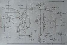
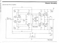
I reverse engineered this module.
You know what?
It sounds nice, dead quiet and stable.
It sounds a tad like an dh220 hafler but a lot more silent and with a better bottom..
I tried it on 50v rails. (Ithink 2x60V would be the right value.)
R8 and R9 set quiescent and offset. Actually 100ma per device, offset is 100mV with R8=R9.
All resistors are 1%
Q1 to Q10 are BC550/560
Video transistors are used as drivers.
I do not understand why C7 has a so large value, though.
What are C10 and P1 for?
Any comments on this schematic?
Attachments
Last edited:
I realised i might be wrong about Iq and offset trimming.
Advice needed.
R8 and R9 are fixed values on this board. I (wrongly?) draw them variable as i empirically moved the offset by trimming one of them..
Cdoms were ceramics, i replaced them using silver micas.
Under 47pf Cdom and with no output zobel neither output self, it oscillates.
I forgot to say: No turn on thump.
Last edited:
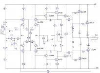
Still a big error.
The loading resistors are ,of course, in the other collectors -positive input side- of the LTPs.
After readings about inverting amps, i realise the added offset setting circuit is unnecessary.
Adjusting R15 should do it.
I'll try it after replacing the LTP pairs by matched transistors.
...Still are missing resistors 47R inserted in the rails for supplying the front end and relative decoupling electrolytics caps...
See the first schematic.
Attachments
Last edited:
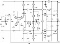
Feedback looks weird.
It s an inverting amp...
This amp is built on the basis of the Motorola application note AN 1308.
Plus
Front end cascoded.
Inverting.
Use of video transistors in vas and drivers.
Lateral mosfets outputs.
Vas more lightly loaded.
I am tempted to try Jfets in the input. (cascoding at 24v.) adjusting the tail current at 6ma and adjusting R10 and R11 to keep the same voltage drop on them.
Plus
Front end cascoded.
Inverting.
Use of video transistors in vas and drivers.
Lateral mosfets outputs.
Vas more lightly loaded.
I am tempted to try Jfets in the input. (cascoding at 24v.) adjusting the tail current at 6ma and adjusting R10 and R11 to keep the same voltage drop on them.
Last edited:
R1 provide the necessary DC bias current for the inverting input,
though its value is not accurately computed as (R3 + R1)(R34)/(R3 + R1 + R34)
should be equal to R15 value (22K) so there is as little dc output offset as possible
since the drop voltage through the bias resistors would then be the same for the two
amp s inputs.
Using jfets in the differential will bring nothing apart some more THD.
That said, interessant design, i ll surely sim it later.
The compensation seems to be shunt if the 47pf caps are connected this way..
Compensation seems to work as there is oscillation with 33pf and none with 47pf.
I checked again the wiring.
Thanks for the formula.
So, total input resistor should aproximately equal R15.
I would be very pleased!
I checked again the wiring.
Thanks for the formula.
So, total input resistor should aproximately equal R15.
That said, interessant design, i ll surely sim it later.
I would be very pleased!
Last edited:
Compensation seems to work as there is oscillation with 33pf and none with 47pf.
I checked again the wiring.
Thanks for the formula.
So, total input resistor should aproximately equal R15.
I would be very pleased!
Hi, Bobodioulasso
Yes, this is theorical value for R15, BUT dont change anything
in any value if you got this amp working properly.
As noticed by Upupa, the designer of this amp made somewhat
a "bricolage" as there s some flaws in his "design".
The most striking is that due to R1 connected to ground, the amp
has an internal DC gain of about 20, that is the dc gain is set by
(R34 + R3 + R1)/(R3+R1).
Adjusting R15 to its theorical value get the amp to going mad and
exhibit a very high output dc voltage..
For the time , this is was resulted of the first sims..
I look further a little later.
cheers,
Wahab,
Thanks for the sim.
Reading the inverting amp theory , i never saw the presence of R1.
Using the formula (R34 + R3 + R1)/(R3+R1), making R1 infinite (i.e. no resistor) gives a dc gain of 1. Is that the wanted value?
The amp works fine though i had to fiddle with DC offset.
Adding my little circuit (post4) i get the dc offset around 0v when warm, and about 100mv when cold.
Not that bad. Though i am waiting for 100 bc550 and 100 bc560 and i will match some of them before to continue.
I will try without R1 and make R15 variable.
Haven't you tried to sim without R1?
Last edited:
Sorry, i made a mistake, the amps seems
relatively functionnal...
The amp has a unity dc gain for the signal since
it s capacitively coupled, but it has a gain of 20
for an eventual DC offset between the two inputs,
inverting and non inverting one.
Removing R1 will slightly increase the ac gain to about
31, but then, R15 should be set equal to R34 to have
a minimal offset....
Are you sure that the two 47pf compensation caps are
not connected to the bases of the bc550/560 rather
than to theirs collectors ?.
In this latter case, it s unstable in my sims..
Yes Cdoms are connected like this.
I have no oscillations on an easy load, though i'll try a more conventional arrangement for Cdom.
You do not tell about distortion, bandwith, etc...
There is also a solution for offset setting as in John Curl Jc3 inverting amp.
I do not find many examples of discrete inverting amps.
Do you know some?
I think you made a typo: don't you mean Rin rather than R34?
I have no oscillations on an easy load, though i'll try a more conventional arrangement for Cdom.
You do not tell about distortion, bandwith, etc...
There is also a solution for offset setting as in John Curl Jc3 inverting amp.
I do not find many examples of discrete inverting amps.
Do you know some?
R15 should be set equal to R34
I think you made a typo: don't you mean Rin rather than R34?
Attachments
Last edited:
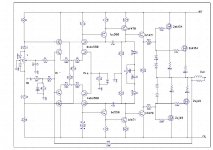
Some experiments done.
Suppressed R1. Offset decreases.
Adjusting R15 does not really act on the offset value.
John curl arrangement on the positive LTP input does not work here.
As it has proven to be working, I will stick with my previous little circuit for offset setting .
I received my bunch of BC550/560 this morning and i will go on matching some, hoping offset will not need to be set anymore then.
A more readable schematic.
Attachments
Yes Cdoms are connected like this.
I have no oscillations on an easy load, though i'll try a more conventional arrangement for Cdom.
You do not tell about distortion, bandwith, etc...
There is also a solution for offset setting as in John Curl Jc3 inverting amp.
I do not find many examples of discrete inverting amps.
Do you know some?
I think you made a typo: don't you mean Rin rather than R34?
no, it s right about R34, as removing R1, R34 will be the only
remaining DC biaising source for the non inverting input,
so R15 should then be set equal , hence the two inputs
will see equal voltage drop through their DC biaising resistors.
Seems that elektor did publish some inverting amps designs,
but it s true that non inverting ones are an overhelming
majority, not only in this mag.
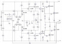
Here some sims of THD and gain/phase response.
I simulated thd with 100PF compensation caps,
since there s instabilities with the original values.
Seems that according to the gain/phase graph,
something like 270pf should provide enough stability..
Changing the compensation to classical miller
does increase THD, but then, i didn t test with
the two 24K vas loading resistors removed.
Will take a look about it, but it will surely
not improve the numbers significantly.
Best results in matter of thd are achieved using
TMC compensation scheme provided the usual vas
collector path is connected rather to the following EF emitter,
as this unload the vas efficently...
Anyway, all in all, the existing shunt compensation
seems to be enough provided the relevant caps
are increased to more influencial values...
Attachments
Last edited:
Thank you very much for your work and your advices, Wahab.
I like the sound of this amp. Probably laterals count for something.
I own also an Hafler DH220 but i prefer this one.
Voices are very nice, they seem magnified. Bass is tight.
Simulation does not look too bad. What do you think?
As i am not very used to read simulation results, i would appreciate your comments.
With the schematic as original and matched input transistors installed face to face, i obtain 5mv offset.
Next step, increase compensation and listen.
Thanks again.
Last edited:
- Status
- This old topic is closed. If you want to reopen this topic, contact a moderator using the "Report Post" button.
- Home
- Amplifiers
- Solid State
- Quadral PA 03 Phonologue