First Open Baffle Build

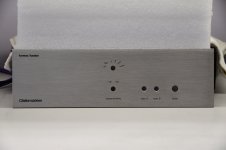
Going to be building my first open baffle speakers and I'm looking to get some opinions. My amp is the Decware SE34I.3 and the idea is to build something small along the design of the Caintuck Betsy. Baffles will be made from either red oak or 1" birch ply, both of which I've got in stock in my wood shop.

I've got a couple of questions and am interested in hearing all opinions.

1) Is the shape of the baffle essential? I see that Caintuck offers a barrel and a tombstone shape. Is this purely an aesthetic or does the shape alter the sound? I can't build them any bigger than 30x18 probably because of the room.

2) Drivers I'm looking at are the Alnico Betsy and the Lii F-15 and Lii F-12. They all seem to have pretty stellar reviews but I'm curious to hear more if anyone has a strong opinion.

3) Do they have to go on the floor? Ideally I'd be putting these on top of a cabinet and the base of the speaker would be about 2 1/2 feet from the ground, about the same distance from the wall behind them. The right speaker would end up about a foot from the side wall.

4) Wings or no wings? Obviously the Caintuck speakers are a bare baffle, but looking around at other designs I see plenty with either hinged or fixed wings coming off the back of the baffle. Presumably these affect the bass response and help shape what's coming out of the rear of the speaker?


Thanks!

Xover help

Hello everyone, I’m pretty new to the diy world and have only done a few projects. My current one is a pair of mtm based off of Jeff bagbys design. I’d love to have a mt version for my surrounds but I have no idea how to change the xover to make that work. Any help would be amazing. Wife said she’d buy me the parts for Xmas if I can figure out what I need. Thanks

Attachments

  • F8D7F425-7BAF-44C4-88E4-58185BDAAF23.jpg
    F8D7F425-7BAF-44C4-88E4-58185BDAAF23.jpg
    597 KB · Views: 136
  • DD6B8573-DC09-493D-A085-964A48DB4D4D.jpeg
    DD6B8573-DC09-493D-A085-964A48DB4D4D.jpeg
    96.5 KB · Views: 140

Discrete buffers

Hello,

I'm in the concept phase of a preamp for my new amp which shall be finished in the next months. (https://www.diyaudio.com/forums/sol...low-nfb-fet-front-bjt-ops-13.html#post6043036)

As this amp has 29dB of gain, I'm not planning to add gain in the preamp as most sources have about 2vrms output. (don't now at the moment what a bluesound node 2I does, if anybody knows…)

I've found plenty of preamp circuits with gain (UGS, DCG3, Dennesen JC80, pumpkin,..., but discrete buffers are not that common. We all know the B1 from Nelson.
As I like to design/change/adapt circuits myself, based on proven designs and not copy existing stuff, I managed to get good performance out of the circuit below.
The power supply must be a really stiff one, as this circuit has loussy PSRR.
The Jung Didden supperreg seems pretty easy to build and looks ideal to me.


Any comment's on how to improve further? Lower noise? Lower output impedance…?

Attachments

  • Buffer V1.0.JPG
    Buffer V1.0.JPG
    61.5 KB · Views: 1,632

Placing CFB op amp in Panasonic Class AA circuit

Placing CFB opamp in Class AA circuit

Hi,
I have a PCB for this circuit. But I want to use a high current opamp instead of other half of of 5532 (the upside down one in schematic). As far as I know, the amplifier in feedback network provides the current.

I have LT1206's which is 250mA capable but they are current feedback op amps. I need to know that which components have to be altered when utilizing LT1206 instead 5532 in feedback network.

I plan to use two single soic-8 opamp to DIP-8 adapter instead of 5532. One half will be NE5534 other half will be LT1206.

887426d1603628273-placing-cfb-op-amp-panasonic-class-aa-circuit-htb1yszclpxxxxbuxvxxq6xxfxxxy-jpg

Attachments

  • HTB1YszCLpXXXXbuXVXXq6xXFXXXY.jpg
    HTB1YszCLpXXXXbuXVXXq6xXFXXXY.jpg
    57.6 KB · Views: 647

Allo Digione Signature w/ USBridge Signature Faceplate

What's included?
1) Allo Digione Signature (pictured)
2) Raspberry Pi 3 + MicroSD card w/ Volumio Installed
3) Allo 5v SMPS

Asking [SOLD] shipped including PayPal (retail is $300+).


Comes with free faceplate for USBridge Signature.


Thanks!

Attachments

  • P1330091.jpg
    P1330091.jpg
    789.6 KB · Views: 258
  • P1330092.jpg
    P1330092.jpg
    1,001 KB · Views: 258
  • P1330093.jpg
    P1330093.jpg
    981.5 KB · Views: 240
  • P1330094.jpg
    P1330094.jpg
    907.9 KB · Views: 238
  • P1330095.jpg
    P1330095.jpg
    897.9 KB · Views: 235
  • P1330096.jpg
    P1330096.jpg
    982.7 KB · Views: 124

Denon DAP5500 optical digital input

Hello fellow audio enthousiasts.

I managed to pickup a DENON DAP5500 preamp. Beautifully built, and a nice added value for my DENON power amp POA2400.

But I'm going to have some work with it...

First issue with it: Right channel is sometimes out. I think the L/R balance pot has to be cleaned or replaced. This has to be an easy fix for me.

Second issue, one of which my knowledge of digital electronics isn't sufficient to analyse what's wrong.

I hooked it up to my digibox via the optical connection. In first instance there seems to be a "lock" on 48 kHz but then it loses its signal.

There might be an issue with IC508 or IC507.
(Someone spilled some fluid on that board and it's gonna need some cleaning and maybe replacing of the IC's?)
--> I added the service manual as attachment. The IC's I'm talking about are on page 23 - 3E & 3F.

Aside from the spilling on the board. Could these IC's be the cause of losing the lock on the 48kHz? Or might it have something to do with compatibility of modern optical connections with the (older) optical DAC?

Thank you for your feedback! And I will keep you updated.

Gr

Will

Attachments

SR60, AX11 or NAP140 Clone?

Hi

I would like to build one of the above amplifiers and as I buy amp pcb's from time to time, I found those three in my collection. I am a lover of Class A amps (and will build a KX in winter), but would like (and need) to build something easier and also a bit more "portable" to test speakers from time to time.

At the moment I have the following boards on my desk:

- A NAP 140 clone from Ebay (Jim's audio) including the PSU PCB. Nice
boards.
- An Apex Audio AX11 (wonderfully etched by a friend). PCB by OlafK
including two PSU boards

- An Apex Audio SR60


Maybe one of you built already more than one of these ?

Some hints would for decision finding would be highly appreciated !

Best regards
Christoph

tcpi (WiFi) interface for sigma studio using a esp8266

[SHARING] TCPi Interface for Sigma Studio, using ESP8266 or ESP32. - Q&A - SigmaDSP Processors and SigmaStudio Development Tool - EngineerZone

I have flashed an wemos d1-mini and that worked.

Hopefully I will have time to actually test this more than flashing the image and verifying that it broadcast the ssid. But I just thought it was to good to not share!

Basically an USBi over WiFi for extremely low cost.

2SA1516 and 2SC3907 replacement?

Hello,
I'm new here, hope this is the right place for this questions.

I have a NAD7400 that seems to have had a tough life.
2 output transistors and some smaller transistors have shorted.

Seems like the transistors are hard to find, and I have another broken Onkyo SR-805 that have 2SA1962/2SC5242 transistors.

Would these work and be appropriate as replacements?
Can I change 2 of the 4 transistors on one channel or should i replace all 4?

Thanks =)

Morel INTEGRA 624 newbbie question for open baffle

Hi ALL

I want to start a project for my youtube channel with the purpose of making a small open baffle speaker about 3.5 feet tall. It is meant to be a MONO speaker. I have gotten a few drivers to try, including horns, but want to start with the simplest array. The morel should be the first, just one 6 inch opening in one of many plywood planks that we will try. Unfortunately I know less than nothing about crossovers and I apologize for this being the 999,99 repeat question, but I am looking for a good off the shelf (Dayton?) crossover to get started with until we get the hang of the final shape of cabinet, etc.

Best solder sucking solution?

Hi Friends;
My repair hobby seems to be keeping me busy these days. It seems like it is time to 'bite the bullet' and invest in a good solder removal tool. I understand there are some expensive gadgets out there, in neighbourhood of $400 (Canadian) and more. Just wondering if there are cheaper effective solutions and/or if I am going to spend that kind of money, which way should I go?
Thanks for any guidance. My application will be likely almost daily use.
Peter in Canada

Torus

Hi,
just a quick question: "Has anybody any experience or thoughts about using a torus/doughnut shape as an open baffle for a wide band/full range driver?

I only ask as the shape seems to me to offer two possible advantages:

1: a degree of waveguide type loading
2: the longest possible path from the front to the rear of the driver for any given baffle size.

(a torus having an overall width of 3 x the central hole diameter)

Digital Designs D4.90 in protection

Have a Digital Designs D4.90 that shows the red protection LED when power is applied. The amp uses the TDA8954J chip as outputs and I have 2 new ones here in case they are needed. I removed the rectifiers to isolate the power supply but still only get the red protection LED. The PS driver board uses a SG3525AP. There was no gate drive to the PS FETS so I went digging around the driver board. I found a shorted MMBTA06 at Q508 and the 47 ohm resistor that fed +12v to VCC of The SG3525AP. After removing and reinstalling the driver board a few times, the gate drive out of the IC started to work so I resoldered it in that exact position, and it has gate output out every time remote is applied now but the protection LED is still illuminated.

The voltages coming out of the SG3525AP pins 11 and 14 are not equal, one is slightly higher than the other. With PS FETS installed, they heat up rapidly, the current draw increases greatly, and then the transformer buzzes before I quickly cut off the supply power. The rectifiers are still out so it shouldn't be anything in the output section, and it does this even with different FETs. I am posting pics of the amp board, pS driver board, and scope shots of the PS gate drive.

Any idea what to check next?

Attachments

  • IMG_20201022_172902__01.jpg
    IMG_20201022_172902__01.jpg
    556.5 KB · Views: 103
  • IMG_20201022_172934.jpg
    IMG_20201022_172934.jpg
    987.6 KB · Views: 101
  • IMG_20201022_172745.jpg
    IMG_20201022_172745.jpg
    921.1 KB · Views: 98

Can someone help me with equivalent/compatible tubes?

I have a SE84UFO2 on order, and it seems it is pretty forgiving about using different tubes. Taking what I see from Decware directly, for the three applications I see:

OUTPUT:
6P15P-EV
SV83
EL84
6BQ5

INPUT:
6N1P
6922
6DJ8
7DJ8
6N5P
6N23P

RECTIFIER:
5U4G
5U4
5AR4
5Y3GT
274B (not all compatible)

What I am trying to understand is the differences, which have multiple models but are otherwise the same tube, or anything else to be aware of.

I did see this sticky, started in 2004 and a TON there. Not being lazy, just wondering if there is one good resource to start with

https://www.diyaudio.com/forums/tubes-valves/38278-line-tube-learning-newbies.html

Thanks!!!

linear unregulated PSU for 3e-audio tpa3255

Hello everyone,

I'm in need of an amplifier for a friend. I want to try class-D, she's looking at limiting her power consumption so class-D seems a natural choice. I have seen the 3e-audio tpa3255, but I'm not sure about the PSU. I have a toroid that are specified at 180VA, 2x12V@8A. I can serialize the windings to get 24V AC, which after full-bridge rectification will provide 32-33V DC.

I'm not sure to understand the spec of the 3e-audio TPA3255-2CH-260W product in regards to power supply, it says "Single supply voltage range 24V~51V(UVP:24V)". I understand I won't get its full power but it's not a problem, the TABAQ I made for her do not need much power anyway. She drives the setup with a bluetooth receiver, and the amp will only have a volume pot between the RCA input and the board.

So my questions

  • what is "UVP:24V" ?
  • will this amp work fine with ~32V DC
  • is the unregulated DC a problem ?
I shall mention that I already have rectifiers and capacitors (10'000 uF, 50V) and even a PCB, so if this PSU is ok I have little costs besides some casing. Can I just add say 4 of these caps and maybe some smaller cap in parallel ?

Thanks for your hints !
Charles

Wattage and impedance.

Hello everyone, forgive me if this has been asked before, or if i am in the wrong thread.

I've gotten my hands on some fantastic furniture, and to make it even better i decided to build some custom speaker units for it, along with a pc case.
Now, i am completely dumb when it comes to audio, and also half deaf to one ear, so it is more about looks than amazing sound quality. I spent days looking around for woofer/tweeter units, then i realized that i have an old 5.1 sound system i could use with a dead dvd player. Since it has to be simetrical, i will order another 5.1 speaker set that is the exact same as the one i own for like 25$.

Now, the plan is to use 1 tweeter and 1 woofer / box and make a stereo setup.
Woofer is 30w 4 ohm, tweeter is 15w 6 ohm, and i plan to use an audio crossover i will order later on.
My questions are fairly simple, despite the lengthy talk.
-Impedance has to be 4+6=10 or 6 for the amp.
-Wattage of the amp has to be 15 for the lowest speaker, 45 as combined, or 30w for the highest part?
-Crossover question is same as wattage 15,30,45, or i can just get whatever that is above these?
-Does the size of the woofer unit matter?

This is the amp i would like to use, unless somebody has something similar in mind, price wise. (this is an aliexpress link) 50WX2 Bluetooth 5.0 Power Amplifier Board TPA3116 Receiver Stereo Home Car Audio Amp USB U disK TF Music Card Player|Amplifier| - AliExpress
Unfortunately Ebay is not an option for me because of my country of origin.
Thank you all in advance.

Alpine MRD-M1005 mono issues

Amp starts, PS works, draws 1.1A on idle. Inputting any signal into the RCA --> amp goes into protect with CUR error.

I've read all of the threads for this amp in this forum.
I've lost a whole day measuring stuff and reading the schematics.

No shorted semiconductor parts, no shorted or opened diodes, blown caps or whatsoever.

There is no class D switching on the gates at the output mosfets/or the output of LO/HO IR2010S chips. Tracing stuff and comparing values to the service manual.

There is +4.2v at the collectors of Q301/Q302 instead of the -1.5v in the service manual.

IC301/IC302 have +4.2v at pin 6 -IN, instead of 1.5v in the service manual. OP amps supply voltages are correct.

Then IC303/304/305/306/307/308 voltages go haywire...

Firstly I thought it's MUTE error but Q305 voltage are right as in the manual.

Any help would be appreciated as i'm lost with this amp...

Attachments

  • Capture.JPG
    Capture.JPG
    95.8 KB · Views: 142
  • Capture2.JPG
    Capture2.JPG
    64.3 KB · Views: 124

Phase alignment on a 15" T-line subwoofer?

I have built a huge choked t-line subwoofer enclosure for a SoundQubed HDX315D2 sub, tuned to around 23hz.

Now this subwoofer is for my car and will stay there, but i thought that this forum might know better about these sorts of "exotic" enclosures.
I mean t-lines aren't rare in car audio, but I can't find that much info either. Especially with a 15" sub.

Now the sub barely fits into my car scraping all four corners of the box, taking almost all the depth also. It's about 80*70*40cm.

The sub and the rounded slot-port are on the same wall, as I've heard this is best for sound quality and SPL. Now the results are lackluster, playing with 3000+ watts it sounds quieter than with the first enclosure that was sub upwards. With about 1000 Watts.

The subwoofer peaks at 17hz, doors closed, so it plays the lows now, but it doesn't do well on the higher notes.

Now I have tried with the sub facing backwards and to the side. I still have to try forward facing, but I don't have big hopes for that.

My next thought is to put the sub firing upwards, because that seemed to work well with the last box, even though it wasn't braced at all or anything.

I'd have to cut a hole in my rear shelf and drop the sub in. (Sub weighs 25kg and the box is 50kg) But the added hole would bring more bass to the cabin anyway, and i could then maybe reverse the sub and have it magnet upwards.

Now I am wondering, don't t-lines rely on the phase-relation of the port and the sub for added low-end? If so, how can i phase-align the sub pointing upwards? I have seen it done with great results, but I just need to know how.


Tl;dr: I'm swapping the subwoofer from the same wall as the port, to another wall. How do I phase-align them?

Ground Lift query

I have put together an external PSU for a preamp. Mains input is via a Roxburgh RIR-022-H IEC suppression filter. The rest comprises an on/off switch (dual pole), Toroid, LM317/337 voltage regulator and finally via a ground lift circuit (Rod Elliott design back to back diodes/10 ohm resistor/100nF cap) just prior to the PSU outlet.
I'm finding a significantly higher noise from the ground lift than from the chassis earth.
The following 'scope grabs show:
Chassis Earth in Yellow, Ground lift in blue
1) The PSU without any connections
2) The PSU with the mains cord connected but not switched on
3) Mains power on and the PSU itself switched off
4) Both the Mains and PSU switched on
5) Shorting the ground lift circuit to earth

Perhaps the Ground Lift is incorrectly placed prior to the outlet (after the voltage regulator)?
Might it be better to connect just after the mains inlet? Between Toroid and voltage regulator?

Scratching my head at this point. 😕
Any ideas?

Many thanks
Tony

Edit:
Sometimes one can't see the wood for the trees.
The 10 ohm resistor in the Ground lift is connected to a buss-bar and was not fully secure. 😱
Tightening the screw has removed the problem and the ground lift now acts as expected and there is little difference now between it and the chassis ground (± 260 vs 150 uV respectively).

Attachments

  • 1) Mains plug disconnected, PSU off.jpg
    1) Mains plug disconnected, PSU off.jpg
    1,012 KB · Views: 118
  • 2) Mains connected but off.jpg
    2) Mains connected but off.jpg
    982.9 KB · Views: 112
  • 3) Mains On, PSU off.jpg
    3) Mains On, PSU off.jpg
    986.3 KB · Views: 108
  • 4) Mains On, PSU On.jpg
    4) Mains On, PSU On.jpg
    991.8 KB · Views: 113
  • 5) Mains on, PSU on, GL shorted to Earth.jpg
    5) Mains on, PSU on, GL shorted to Earth.jpg
    1,014.9 KB · Views: 106

Ultra low-cost receiver (Tuner+Amp) project

Motivation
Traditional FM radio has its benefits- one of which is an unlimited supply of free music. With the advent of local radio stations that play a variery of music from the past and do't talk too much, listening to radio has become interesting again, at least for short periods of time.

A line-in will be needed as well, for an MP3 player or CD player or both.

Bluetooth is also a possibility.

Feasibility Testing
The feasibility of this project is already tested, using a transistor radio costing less than $10. The sound quality is fully acceptable, and considering that the radio uses an LM386 chip, albeit it bridged mono mode, sound quality is not expected to be an issue.


1) Satellite subwoofer home theatre system through headphone output

Sound quality - suprisingly good, though lacking bass. Distortion most probablt due to broken antenna.

2) Un-enclosed Radio Shack 6" 40-1011 woofer driver with sensitivity of 93 dB/W/m

Acceptable sound quality

3)Sony SS-G333ES speaker

Sony SS-G333ES on thevintageknob.org

These are large speakers, consisting of a 8" woofer, mid-range, and a high quality tweeter.

Sound quality was acceptable, something I could live with. Sound pressure levels at 1 metre was measured at 75dB/W/m at half volume with distortion attributable mainly to the FM reception. Connecting a long wire to the FM terminal cleared things up considerably.

All this from a transistor radio powered by 3 volts of batteries.

FM Section
The FM IC used on this little radio is a CD9088CB. Output is to one speaker although the headphone output seems to be stereo,

Tonegen Tweeter Replacement? Axis LS28/LS88

I know these sorts of questions come up all the time and there is no easy answer...

I have a set of Australian Axis speakers - LS88 and LS28 and a matching centre. The high frequencies on the LS28 and LS88 have all but disappeared - which I attribute to the aging Tonegen tweeter (94L65DS-03HD; 442TND).

I believe these tweeters were used in many speakers through the ages.

There is even a thread on re-doping them (or a very similar model):
How to Re-Dope Snell Tonegen/Foster Tweeters (Model E, J, K; gens. I & II) | Audiokarma Home Audio Stereo Discussion Forums

In addition to the re-doping, there is also ferro fluid that may or may not need to be replaced depending on if or if it isn't in there. In any case, I'm not sure if I'm up to taking these apart.

Anyway, have been looking for a replacement - unfortunately they have an in between cut out diameter (~94mm) and the LS88 has an extra magnet glued to the back..

Any ideas?

Mmini regulator (sample offering)

Hi
My friend designed two regulator with very small size. He is willing to offer PCB sample to member on diyaudio forum.

Dual regulator : SIZE: 82mm X 59mm
Positive regulator : SIZE: 65mm X 41mm
Supply voltage range : 5V -- 80V

here are the pics of the regulators:
dual
15VUMRDual.jpg

positive
PRO2Power.jpg


This is the PCB:
dual
NEWUMRDUAL.jpg

positive
pumr00f1.jpg


Schematic:
dual
UMRsch01.jpg

positive
PUMRsch01.jpg


The mounting on chassis:
UMRHT.jpg


each member from DIYAUDIO can ask for one sample PCB(dual or positive). Because the different voltage has different BOM, please tell me output voltage you need. Only 20pcs of samples for each reg.

Applyer only pays the registered airmail shipping fee 3.00USD.
My email address: coffin@diyzone.net

cheers

Coffin:smash:

Good software/app for making drawings of rooms and cabinets?

I'm going to be helping someone put audio in a newly purchased home, and also want to do some projects in my own. Also, once I get past some personal stuff, I want to FINALLY make* some custom speakers and matching cabinets.

I've made some crude albeit scaled room sketches in PowerPoint, but that's not going to serve easily for 3D cabinets. And for rooms, I feel there must be something simpler. Once upon a time I used Google Sketch-Up, or are there better choices by now?


*Not myself, my detailed woodworking days are past. Any LA-area recommendations for cabinet makers (speakers and stereo cabinet, not kitchen ha ha) very welcomed.

Antique radio bluetooth mod - stereo/mono conversion

Hello all

I have got an antique radio with a nice casing, and volume knob that I am thinking of repurposing.
I would like it to have a line-in, and a bluetooth function. Unfortunately the radio can only accommodate one speaker, and I think i will look for a 5.25 inch driver.

I want to power it with a suitable board. I found many, with the appropriate power, line in, and bluetooth, and volume control (which i intend to interface with the original knob).


Here is a good example of a board I'm considering


But these are all stereo. I am a little at a loss as to how best to convert to drive a single speaker. I see advice about combining the line-level signal using simple resistor Y-shaped configs, but not clear about how to combine a class D L/R output to mono.

Any tips would be greatly appreciated.

directly coupled class A buffer for low-voltage headphones (work-in-progress)

After lurking for a bit a looking at lots of designs, I've started cobbling together my own.

This is a class A buffer for low-voltage headphones, with no input or output capacitors (similar to the directly coupled B1 buffers in this forum).

This is intended to drive my Etymotics, which only need about 0.2V.

There are three "channels": right, left, and a virtual ground return.

The source follower is an IRF510, and the constant-current sink is my tweak on something jerluwoo posted in https://www.diyaudio.com/forums/sol...ource-ccs-audio-applications-post4785961.html

It seems to simulate fairly well 🙂

Haven't actually built it yet, that's next 😀

This is my first "real" attempt at making an amp, so any and all feedback is welcome!

Attachments

  • hpa-nocap-IRF510-TIP122-r2.asc
    hpa-nocap-IRF510-TIP122-r2.asc
    22.6 KB · Views: 107
  • Screenshot_2020-10-06_03-33-41.png
    Screenshot_2020-10-06_03-33-41.png
    31.3 KB · Views: 697
  • Screenshot_2020-10-06_03-33-18.png
    Screenshot_2020-10-06_03-33-18.png
    84 KB · Views: 702
  • Screenshot_2020-10-06_02-42-09.png
    Screenshot_2020-10-06_02-42-09.png
    71.9 KB · Views: 670
  • Screenshot_2020-10-06_02-41-44.png
    Screenshot_2020-10-06_02-41-44.png
    71.7 KB · Views: 666

Eminence Delta Pro 18 A in prism sealed 150 liters

Hello

This thread is the continuation of a cartoon that started here:


Vintage JBL for subwofer

I transcribe the text of my notes:

DEFINITIVE DECISION :
CORNERS !
I will use this two furniture, the white will be for the box and the red for the front panel.

Box:
Prism
Volume 300 liters gross
Design: sealed
QTC: 0.550
Perfect transients, although less SPL, this is compensated with a gain of + 3 db in each box when increasing to this volume ..
So for the same SPL will need half the power (watts)

These pieces of furniture have been a gift from a friend who did not use them anymore.

They serve ? he asked me .....

The next day they were in the hall, WAF asked where we would take the dog for a walk, for the same place that we will enter and leave, I answered, or is not he another member of the family?

The prism (irregular) will be 0.50x0.50x0.70, and the height of the box of 1.40 meters.

Soon I will attach the results of the simulations with WinIsd

Ohhh, I will have to make many gifts (and many invitations to go out to dinner) to my wife, these monsters are not easy to accept in a living room ....
I am a lucky man, yes sir ! 😉

Attachments

  • IMG_20181028_184053.jpg
    IMG_20181028_184053.jpg
    820.2 KB · Views: 1,801
  • IMG_20181028_181504.jpg
    IMG_20181028_181504.jpg
    870.7 KB · Views: 1,752

Transformer based 6db preamp

My latest diy preamp adventure. -/+ 24v Linear Supply. Sparkoslabs regulators. LSK489 for the jfet’s. 6 layer PCB (s/g/p/p/g/s). Startup / shutdown muting.

Balanced -> LL1676(1:2) -> jfet follower -> 10k ladder -> jfet follower -> dc blocking cap -> RCA

I will post measurements soon.. the in/out are flipped on the case.

Attachments

  • D36E5E56-57CC-4523-AEB4-917D24256B2F.jpg
    D36E5E56-57CC-4523-AEB4-917D24256B2F.jpg
    1 MB · Views: 740
  • 2113D6D5-EB64-4403-A71D-1E9C6FE63446.jpg
    2113D6D5-EB64-4403-A71D-1E9C6FE63446.jpg
    979 KB · Views: 709
  • 1EE2312B-77E5-417B-8327-309723928F88.jpg
    1EE2312B-77E5-417B-8327-309723928F88.jpg
    964.1 KB · Views: 687

GF1002 (PAM8403) not working but overheating?

Hello everyone,

I am building a project with a DF player and a GF1002 (based on PAM8403). The problem I have right now is that by pressing the play button on the DF player, there is no sound, however the GF1002's IC is heating up. I have attached my current wiring diagram.

This scheme worked before I hooked everything on a PCB, which probably have destroyed my previous GF1002 (+ and - were shorted) - it also heated up.

However now I have brand new both DF player and the GF 1002. When I connect only 1 speaker to DF player (to pins SPK1 and SPK2), it works.

What have I done wrong?

Attachments

  • wiring.jpg
    wiring.jpg
    244.6 KB · Views: 1,095

Full Digital Amplifiers with PSVC (Power Supply Volume Control)

Hi,
According to TAS5558 datasheet:
The TAS5558 supports volume control both by conventional digital gain/attenuation and by a combination of digital and analog gain/attenuation. Varying the H-bridge power-supply voltage performs the analog volume control function.The benefits of using power-supply volume control (PSVC) are reduced idle channel noise, improved signal resolution at low volumes, increased dynamic range,and reduced radio frequency emissions at reduced power levels.

The TAS5558 also features power-supply-volume-control (PSVC), which improves dynamic range at lower power level and can be used as part of a Class G Power Supply when used with closed-loop PWM input power stages.

I wonder is there any examples of Full Class D amps which implemented this (or similar) concept on volume control stage? I think this concept overcomes one of the big concerns in audio when used with full digital amps.

Attachments

New enclosures for PC speakers -

This project is about creating better enclosures for the 3.5 inch speaker drivers that came with my PC speaker system that was converted to an amplifer in this thread:

http://www.diyaudio.com/forums/chip-amps/283845-pc-speaker-electronics-amplifier-conversion.html

Removing the 3-inch speaker drivers and testing them externally yielded some interesting and encouraging results. Placing them in cardboard boxes generated a surprising level of clarity and some semblance of bass.

The speakers do sound better when 'liberated' from their enclosures. There are several reasons for this, as far as I am able to ascertain. The speaker grille probably cause a lot of diffraction, and also resonances. The box formed by the front of the speaker enclosure and the speaker box also causes some level of 'boxiness' and resonance.

I hope to design and build speaker enclosures for the speakers.
Specifications:

Impedance: 4 Ohms
Power Handing : 3 Watts
Size : 3 inches

Measurements:

Frequency response : 100Hz to 12,000 Hz (pure tone)
Max output : 75 dB at 1 metre

long actuator tumbler switch

I am looking for a SPST tumbler (toggle) switch which has a long actuator/handle (at least 30 mm long).
When browsing the internet, I stumbled across a switch from APEM in its 600H series.
In that series APEM has also types with actuator lengths 30mm and 40mm. But looking for a supplier I cannot find that type.
Can somebody on this Forum help me with this problem.
It is in fact not important which manufacturer but as long as it can supply that 30mm actuator it is O.K.
In the attachments I show which type I mean.

Attachments

  • Apem-Tumbler-Switch-2.png
    Apem-Tumbler-Switch-2.png
    85.1 KB · Views: 135
  • Apem-Tumbler-Switch.png
    Apem-Tumbler-Switch.png
    80.8 KB · Views: 129

Airplay data dropouts bug or not?

Hello,
I am investigating one problem with airplay streaming involved in signal chain. Longer story is here
Short story is that it began from shairport-sync issues. But i got same problems without shairport-sync involved.And that is just mind blowing. I played 20khz sine signal from mac to airport extreme latest version and firmware and got the same crackling sound due to dropouts about 384 samples lenght. I am out of ideas, so want to be more sure that not only me getting this. Anyone having apple at both ends could test this. Just generate 20khz sine over airplay to other apple end and see if you experiencing this. Why 20khz? Because this is the most easy way to find a problem if it exist. Make sine just below 0dbFs and play. Please play for 2minutes at least. The problem could take time to appear.
Anyone experiencing the same please let me know.

Thanks

Attachments

  • dropouts_about_342samples_lenght_-20db.JPG
    dropouts_about_342samples_lenght_-20db.JPG
    201.4 KB · Views: 68
  • jack_alsa_glitches.JPG
    jack_alsa_glitches.JPG
    147.7 KB · Views: 69

Removing Scratched in Speaker Veneer

I have Mission 770 with pretty sever scratches on the top ... any tips for getting them out - short of re-veneering, which I'll not do

Pictures show after light sanding with 600 grit to remove high spots, light soft pencil scribbled to identify "layer", light sanding with 320 grit to remove pencils marks - damp wipe to remove sanding dust. Still looks like hell.

Attachments

  • IMG_9910.jpg
    IMG_9910.jpg
    831.9 KB · Views: 203
  • IMG_9911.jpg
    IMG_9911.jpg
    994.8 KB · Views: 199

Dealing with internal standing waves and port leakage

While doing some experiments on my speaker, I placed a piece of plywood in the back of the enclosure behind the woofer at a 45 angle pointing upwards:

attachment.php


That didn't really change the output of the woofer, which was my original goal, but I discovered that it significantly reduced (smeared) a 850Hz peak I had in the port output.
When I flipped this reflector to point to the bottom of the enclosure, that effect was gone and the peak came back.
I also tried putting a piece of high density rockwool in the middle of the enclosure behind the woofer, and the effect was kinda midway between the reflector and no reflector.
(see attached measurements)

As far as I understand, the reflector changes the path of the wave from the back of the woofer, shifting the resonances to different frequencies, and overall, scatters it around the enclosure.
I'd love to hear your thoughts and explanations, maybe there's a better/easier/more proper way to achieve this?
Also, if you know any good articles on how to deal with the sound inside the enclosure, please share. There is plenty information about stuffing but I didn't find much about the cabinet shape, construction, effects of slanted walls etc.

Attachments

  • p1.jpg
    p1.jpg
    116.8 KB · Views: 345
  • p2.jpg
    p2.jpg
    112.7 KB · Views: 1,040
  • d1.jpg
    d1.jpg
    289.5 KB · Views: 350
  • d2.jpg
    d2.jpg
    290.1 KB · Views: 341
  • d3.jpg
    d3.jpg
    279.7 KB · Views: 205

Replaced Audax HD100's with Audax tw025a0

Dear people from Diyaudio,

I have struggled quite a bit before trying to solve my issue with the help form this forum. I play with a pair of wonderful mission 717's with a bit of an upgraded cross-over. After modifying my amplifier I heard an issue in my speakers. Both have a slightly different version Audax Hd100 tweeter. To solve the problem I bought the tweeter known as the "Direct replacement for...". After measuring I deal with a +/- 6dB difference. The man who sold me the tweeter kindly helped me and we measured an L-pad for the tweeter. Sadly enough just an L-pad doesn't solve my problem.

To sketch the situation at this point, the original crossover is as following:
Low pass: 1,6mH coil in series.
High pass: 6,8uF capacitor in series, 0,20mH paralel.

Simple, yet effective.
The current situation follows this + a 2,7 ohm resistor series, 5,6 ohm resistor paralel. With this impedance making it a 5,8db attenuation.

I can't honestly say that I feel like I need this or that, it's just not 'there' yet, and I'd love to get some suggestions. I made my filter external so I am able to 'play around with it'.

Hope someone can put my tweeter on the right track, I can feel it's 'almost there'....

Inductance of low pass filter & bass driver on group delay ??

Hi,


I am lost in the uderstanding of group delay and also on how to choose the inductance characteritics of a bass driver.


I believe to know a coil for a low pass is adding a lot more of inductance that the driver has itself at those low frequencies. How much is it important in the choice of the bass driver please ?


What about a 8" having a Le of 0.2 uH like modern drivers with low efficienty and trade offs with older design with maybe 0.5 to 1 uH ?


My understanding is the lowest inductance gives the best group delay or am I mixing the concepts, i.e. missunderstanding the thing ?


I especially asking myself what Le range should be preferabily chosen when we need to pick up a mid bass drivers, these 6" to 8" drivers that are asked to make 50 hz as 800 hz ??? Is there a threshold where we should don't care anymore cause too much difficult to manage below a limit ? For instance 100 hz or else at seing for instance some waerfall in the bass areas ?!


How much should I care of the inductance in the datasheet, then in the coil filter for a first order low pass, please ?


Sorry if I am mixing up the thing too much btw...


Many thanks if you could beginn to enlight me...or give me simple path to follow fon howw to consider the Le of a bass driver.

4P1L Alternative

I've been using 4P1L as PP driver in my GM70 PP amplifier and like the sound. I used it in place of 46 as they are hard to get. The 4P1L is transformer coupled to the GM70.

As usual the 4P1L is very microphonic and that is beginning to concern me. I'm not entirely sure if it makes a difference but if the music is loud and cut off suddenly (lifting the cartridge off the record) a ringing can be heard that fades out; like a small bell.

I'm looking for suggestions for an alternative that is relatively easy to get, not too expensive. Preferably directly heated but I might have to concede on that.

ADCOM GFA-585 Power Amplifier Rear Heatsink Assembly Pair Only

Used ADCOM GFA-585 power amplifier rear heatsink assembly pair in excellent condition. They do not include any semiconductor devices nor emitter resistors, and possibly other parts may be missing. Sells and ships to USA residents only. $125.00 plus shipping; PayPal with transaction fee.

Attachments

  • IMG_2416.jpg
    IMG_2416.jpg
    551 KB · Views: 141
  • IMG_2417.jpg
    IMG_2417.jpg
    592.2 KB · Views: 129

FS Troels Gravesen Faital 3WC-15 high sensitivity floor standers

These speakers are the original ones as built by Troels - I was lucky enough to buy them off him directly as he was short on space and another one of his projects had to be moved on. Speakers will come with full build / crossover details.

UK buyer preferred, free delivery in England/Wales - dispatch outside of this possible but it might be costly.

Asking £3000 based on parts cost - good deal considering the kit price and sheer amount of baltic birch plywood used and huge amount of time Troels put into these.

They put most commercial speakers to shame - for example Spendor D7.2 at over £4K is nowhere near the performance of these (I have directly compared). I personally believe something like the Spendor classic range or ATC SCM100 SE would be a more comparable speaker.

These ones are fitted with the beryllium tweeter.

These have similar DNA as ‘The Loudspeaker’ but in a smaller package.

Original webpage for the build:Faital-3WC-15

Condition is mint.

Attachments

  • 48DDBC78-8009-47EF-8E08-4AE38140B1AA.jpeg
    48DDBC78-8009-47EF-8E08-4AE38140B1AA.jpeg
    399.3 KB · Views: 776
  • 0F4B4062-250E-4E09-887D-9914D9573836.jpeg
    0F4B4062-250E-4E09-887D-9914D9573836.jpeg
    260.8 KB · Views: 769
  • 91BAA40F-1AD3-450A-99BC-7D3254714616.png
    91BAA40F-1AD3-450A-99BC-7D3254714616.png
    260.5 KB · Views: 742
  • EDBDF7AE-2CE9-4473-8A3B-53F9308946EF.jpeg
    EDBDF7AE-2CE9-4473-8A3B-53F9308946EF.jpeg
    380.9 KB · Views: 758

An unusual electrostatic AMT DIY approach - an attempt, at least ...

As a happy Quad 63 listener, Dipole-DIY-er and fascinated by the AMT Mid-Tweeters ... why not face the challenge to mix that all together into yet another, this time slighty more experimental DIY project for me: A non-standard AMT with an electrostatic drive ...
ES_AMT_1.jpg

I started with the Idea of a folded AMT-curtain which would have some 4:1 depth-to-width ratio and would result in some sort of max. 4:1 compression ratio, if the membrane would perfectly move in parallel (which is not the case). I designed not much deeper, because of possible lambda/4-resonances.

The membrane is hold into it's curtain shape by carbon rods which are manteled by shrinking tube. These rods can rotate in the plexyglass holders so to allow some repartition of the membrane tension.
ES_AMT_4.jpg

On both sides of the array there is a V2A steel rod, letting stretch the membrane and slightly play with the tension. After the tension seems ok, the membrane has been further stretched with a hot air gun. The electrostatic load of the membrane is fed by one of these V2A rods.
ES_AMT_2.jpg

Each fold of the electrostatically charged membrane has on both sides 5 straight copper wires driving the audio signal to it. Because everything should be symmetric, in theory there would not be any lateral forces on these copper wires. Wirewise, a wire either pushes, or pulls both adjacent menbrane folds. All these 5-Wires-Arrays are alternatively fed by the high tension audio signal. One set is fed from the top, the other set with opposite polarity from the bottom. The distance from these arrays to the membrane is some 2mm, as everything is set up on a raster of 2.54mm.
ES_AMT_3.jpg

The transformers are 220V-5V types, which gives a theoretical ratio of 1:44 when inversely used. To archieve enough high Audio signal Voltage, two of them are used, totalling to a ratio of 1:88. In order to get some 4kV audio signal, the nominal 5V inputs of the transformers must be fed with some tenfold 45V...50V. Therefore, to avoid saturation of the iron core, this setup must not be fed with signals below the tenfold of the nominal 50Hz, e.g. not below 500Hz.
Transformers.jpg

The static high voltage is provided by a Cockcroft-Walton multiplyer, fed by a commercial inverter for cold cathode lighting, the latter outputting 700V ... 1100V / 5mA at a frequency of 30kHz. The diodes are 2kV/3A types, the capacitors are Wima MKS 2kV/100nF types. So at the end of the miltiplyer chaint there must approx. be some 4kV.
CockcroftWalton.jpg

So, hooking all together ... and driving it with an old faithful Yamaha AX 590.

Three different membranes have been measured. Twice (red/green) membranes cut out from an aluminium damped emergency blanket. KISS for the beginning, because it is a standarded and readily available (I know, I know, way too much conductivity ...). This kind of membrane material is very noisy by itself, very self-resonant, which leads to really messed-up acoustic results between 500Hz ... 5kHz, full of resonances. And also a huge and broad peaking above 10kHz. Because of these resonances, something completely different was used for a third attempt: Give it a chance with a self-adhesive aluminium ribbon, all along with it's protective PE-strip-off-layer (blue). This provides a nice self-damping sandwich membrane, a much smoother sweep audition, but an akward loss of SPL around 10kHz. So in the end, none of these two membranes were suitable. And I am reluctant to dive into self.made soap/graphite/magicmixtures coating of unobtainable membrane brands. Unless someone knows THE solution ...
Amplitude.png

Besides the resonances there was way too low SPL: 80dB, and when driving it louder, then the sparks went firing ... for the case of the safety blanket, each spark was evaporating some of the aluminium coating (sort of a nice self-limiting process, indeed). The foil itself was robust: The sparking was not punching a hole into the foil.
Membrane.jpg

So all in all the project is/was a fail until now. But it was fun, and I learned a lot about electrostatic LS. And I luckily am still alive, despite handling HT.

I have not given up completely, though: Maybe someone has some most welcomed constructive critics / remarks / hints?

Attachments

  • ES_AMT_1.jpg
    ES_AMT_1.jpg
    156.6 KB · Views: 727
  • ES_AMT_2.jpg
    ES_AMT_2.jpg
    93.7 KB · Views: 616
  • ES_AMT_3.jpg
    ES_AMT_3.jpg
    126.4 KB · Views: 587
  • ES_AMT_4.jpg
    ES_AMT_4.jpg
    108.2 KB · Views: 606
  • Transformers.jpg
    Transformers.jpg
    141.8 KB · Views: 572
  • CockcroftWalton.jpg
    CockcroftWalton.jpg
    161.6 KB · Views: 345
  • Amplitude.png
    Amplitude.png
    40.9 KB · Views: 380
  • Membrane.jpg
    Membrane.jpg
    70.6 KB · Views: 376

B&K 1640 Linear Regulated Power Supply

B&K 1640 mobile equipment power supply in good condition with manual. Discrete linear regulated design provides 3 amp continuous current and voltage adjustable from approx 10 to 15 volts DC. Vintage 1980s. Has auto-reset overcurrent switch.

Sells and ships to USA residents only. We have closed our audio shop due to retirement. $40 plus shipping; PayPal with transaction fee added.

Attachments

  • 1640.jpg
    1640.jpg
    117.2 KB · Views: 141
  • 1640_2.jpg
    1640_2.jpg
    110.4 KB · Views: 139
  • 1640_3.jpg
    1640_3.jpg
    145.6 KB · Views: 140

Analog Devices AD743KN & AD745JN Opamps

I have NOS genuine Analog Devices AD743KN (9) and AD745JN (11) for sale. The 743s will work well in ROTEL RQ-970BX phono preamp upgrade and the 745s are excellent for ADCOM GFP-565 preamplifier phono stage upgrade (along with required resistor and capacitor changes). These were sourced from an authorized USA distributor and have been long out of production. We have closed our audio service/upgrade shop due to retirement. $20 each plus shipping. PayPal with transaction fee added. Sells and ships to USA residents only.

Attachments

  • AD743.jpg
    AD743.jpg
    128.2 KB · Views: 88
  • AD745.jpg
    AD745.jpg
    105.7 KB · Views: 86

Hello My name is Brad.

Hello everyone. My name is Brad. I have been lurking around this site for many years(about 20). Back in my teenage years, I was really into home and car audio during the early to late 1990's. Now that I am a married homeowner, I have an interest in building a few projects for my house and as well as my cars. A lot has changed since the late 1990's, and I would like to catch up on the current technology. Back in the 1990's I was a huge Cerwin Vega fan, and I am currently a fan today. Going back 25 to 30 years ago, I remember amplifier power was quite expensive being between $2-$5 per watt. Today, I see that there are amps out there with a lot of power for significantly less money. I also see many new companies out there. I am glad to start posting, as I have so many questions since I was active building stereo systems over 20 years ago. Thank you Brad

Sub miniature tube headphone amp site.

Hello, does anyone here know what happened to the site of an Korean or Taiwanese Sub miniature tube headphone amp site ?

I visited the site last in 2013 but i cant find it anywhere anymore.
This guy made beautiful tube amps in, to me, impossibly small mint tins.

All battery operated.

I downloaded one project of his the "amp head micro" but even googling on that name or reverse picture lookup doesn't give any results.

If any one knows where to find more documentation that would be great.

Kind regards Oliver


His name is sijosae. Old site is "http://www.headphoneamp.co.kr/ftp/sijosae/Gallery/"

Attachments

  • Amp_head_micro.png
    Amp_head_micro.png
    56.8 KB · Views: 455
  • FinishedTop.jpg
    FinishedTop.jpg
    808 KB · Views: 584

Troubleshooting low frequency humming in PC speaker set

My Logitech Z-2300 unit suffers from an audible low frequency humming. My observations about the humming are as follows:

  • The humming comes from both satellite speakers and the woofer speaker. Though I'd say the humming from the satellite speakers is slightly louder.
  • The humming is independent from the volume setting on the control remote
  • The humming is present with and without an audio source connected to the 3.5mm input
  • When disconnecting the satellite speakers and the woofer speaker, the humming is no longer audible. Though I can hear a similar humming (same pitch) originating from the toroidal power transformer, but it is much less audible.
  • The humming remains audible when only the woofer is connected (with satellite speakers not connected) and when only the satellites are connected (with woofer speaker not connected).
  • The humming was also present in my previous home.
Upon researching this issue on google, the most probable culprit would seem to be a ground loop. Note that the unit does not have a ground terminal (it uses a two terminal plug). I've disconnected all other appliances in the room and connected the speaker set directly to the wall socket, but the humming still persisted. Nevertheless I have been unable to exclude a ground loop as the cause of the humming. Can a ground loop be a problem considering the device is not grounded to the mains? Perhaps the issue lies with the grounding inside the unit? Would this manifest itself as a humming tone?

Upon googling further, I found a common problem in the Z-2300 is a subpar mechanical joint of two ground wires. See Logitech Z-2300 subwoofer hum solved! | YourITronics. I replaced the mechanical joint with a soldered joint, but unfortunately this did not mitigate the humming.

I then spend some time measuring the power supply circuit of the Z-2300 with my DMM but I couldn't find anything suspicious: mains voltage appeared over the primary coil, the secondary was at 40.2V AC and I measured 54.2V DC after the bridge rectifier. Measuring the rails for the MOSFETs, my DMM reported an initially high ripple on the DC voltage but after a while the reading would stabilize to less than 1V (note this was with no outputs connected).

I then proceeded to try and de-solder the output caps on the bridge rectifier (in order to measure their capacitance, I don't own a ESR meter) but have been unable to desolder them due to all the epoxy on the PCB. As the two big caps still look in good condition in the pictures linked below, I'm doubting whether they are causing the humming.

The similarly between the humming from the transformer and from the speakers leads me to believe the transformer might be the culprit? While reading on transformer humming, I typically read about mechanical humming. In this case the humming from the transformer sounds more electrical though. Is there anything I can try to determine whether the transformer is the culprit? Unfortunately I don't have access to a bench power supply, I only have a DMM (though it can read capacitance and conductance).

Finally, can anyone suggest any further steps for troubleshooting the issue?

Link to imgur album.


edit: replaced images with link to imgur.

Infinity RSA 250 repair.

Looks like this is a "rare" amplifier? Not much information out there on it. I have been running it as my 3rd spare LOL.


Started doing a weird thing where there would sometimes be no audio, but if I turned the volume way up it would start to play for a while, then stop. Figured I'd open it up and see what's going on.


One of the MOSFET's (looks like the power supply section) let out the magic smoke. 2 more have bad solder joints. Seems simple enough, but I am not sure what is the correct part.


Silk screen on the board says T3055, Part itself is BUZ71A. T3055 is kind of generic, lots of parts come up. BUZ71A has some more specific results, but seems to be obsolete. Found one site that had STP16NF06 as an x-ref.


I understand it is risky buying parts on Ebay, but what about Amazon?? Or, best to stick with the reliable part houses (Mouser, Newark, etc.)


Looking for someone smarter than me with experience to suggest the best route for replacement part?


Thanks!

FS: legendary Paravicini The Head TX-4 MC SUT

Hello,

Sadly, but I am selling my Paravicini The Head TX-4 MC step-up transformer. It is in very nice condition, with very small signs of usage, but considering it's age I would consider it perfect. I've been using it for many years with great pleasure and I hope it will get into good hands.

It's a legendary SUT with magnificent sound. According to my best knowledge only 200 units were made, this is No.28. They show up for sale very rarely so now it is your opportunity to get one.

Item is located in Budapest (Hungary) and I am happy to ship it globally. I will pack it very carefully.

Asking price: EUR 2.290 plus shipping

If you are interested, please send me a PM.

Attachments

  • IMG_2199.JPG.330cf6f8643c54c75d5674496afe6636.JPG
    IMG_2199.JPG.330cf6f8643c54c75d5674496afe6636.JPG
    173.5 KB · Views: 343
  • IMG_2200.JPG.0c993e4c2ea27a3cfe90b56d92ac6e94.JPG
    IMG_2200.JPG.0c993e4c2ea27a3cfe90b56d92ac6e94.JPG
    192.6 KB · Views: 401
  • IMG_2201.JPG.39279a88baa2d3d5d28d48c5e5f4c0b6.JPG
    IMG_2201.JPG.39279a88baa2d3d5d28d48c5e5f4c0b6.JPG
    193 KB · Views: 317
  • IMG_2202.JPG.a2f164f7b2e853a384ead03a775857fe.JPG
    IMG_2202.JPG.a2f164f7b2e853a384ead03a775857fe.JPG
    157.2 KB · Views: 309
  • IMG_2203.JPG.680e8f320f554ebb673f7a7a425bf6f4.JPG
    IMG_2203.JPG.680e8f320f554ebb673f7a7a425bf6f4.JPG
    217.2 KB · Views: 283

FS: Lyra Clavis D.C. with silver coils

For sale is my Lyra Clavis D.C. cartridge rebuilt by ANA Mighty Sound in 2018. Since then it has been played only a few hours and it has been sitting in my drawer.
ANA Mighty Sound just recently checked it and they found everything perfect. Cartridge looks and plays as new.

Rebuild includes:
- silver coils
- Ogura PA stylus on boron cantilever
- new silicone damper

VTF: 18 mN
Coil impedance: 6,1 ohm
Tracking: 100 micron / 315Hz

As you can see it tracks better than when it was brand new.

Don't underrate this cartridge, with the rebuild its quality has been raised significantly, with the silver coils inow t plays in a much higher league.
Amazing 100 micron tracking ensures not to miss a note from the record.

Asking price: €790 including express international shipping.
I am also open to serious offers.

Photo shows actual item. You can buy with confidence, I am long time member on DIYAudio.

Tx8BeGq.jpg

nW6U9Kg.jpg

YhGLvtm.jpg

QRvOD4Z.jpg

e2dzVOQ.jpg

9WZKC4Ph.jpg

Nv4Aqueh.jpg

tEzL31u.jpg

FS: Audio Tekne MC-6310 low impedance MC cartridge (silver coils)

For sale is my Audio Tekne MC-6310 low impedance MC pickup. It has been rebuilt by Ana Mighty Sound and it sounds very lovely.

Rebuild includes:
- new coils made from silver wire
- new cantilever with Line Contact stylus
- new damper (silicone based)
- cleaning, alignment, testing, fine tuning

VTF: 20 mN
Tracking ability: 80 micron / 315Hz
Coil impedance: 3,4 ohm

Stereophile recommended components under phono cartridge category class A.
New price was around 4200 euros.

Asking price: €1450 including FedEx International Priority shipping.
I am also open to serious offers.

I have the photos of the rebuild and I am happy to share some with potential buyers.

3kAnENz.jpg

ktsWIRj.jpg

DniFGKG.jpg

sSNqwhn.jpg

s8skzw5.jpg

KF87qRn.jpg

YzuiREL.jpg

d0uztKU.jpg

lFPgnrS.jpg

Phase issues

Hello,

I've got a pair of small fullarange satellites in a 2.1 system with some serious phase sifting in the low-mid treble region. The sats consist of the PS95 driver in a 2.8 liter box with a 14cm baffle without any passive filters, and a 8's sub for everything lower than 100hz. Take a look at the REW measurement ( dont mid the high bass output this is just how i like to hear my computer speakers with some extra bass) i am curious about the multiple phase shifts in the 1k-5k region. I dont notice something significant by ear, but maybe that's because i havent listened to a lot of speakers. The mesurment is taken form my ear high right in the middle of the speakers (which are about 1 meter apart and have a slight tilt inwards. Is this significant? what might be causing this?

Attachments

  • das.png
    das.png
    316.6 KB · Views: 137

Tricolumn speaker with f88 Fountek

An externally hosted image should be here but it was not working when we last tested it.


Here is an idea of a tricolumn speaker using the f88 (or other small speaker). I've designing it using the specs from the paper "Now,a tricolumn- build this efficiente column spekear" by R. N.Baldock. Two questions:

1. How to model it with Hornresp? Simply use parabolic sections? There are some discontinuities in the interfaces between the 3 cylinders (one of them is not a cylinder)...

2. Or just go for it with a thumbnail calculation based on the resonance frequency (L=c/(4*f)) and taper ratio of 1/3, height of the inner tube d=2*L/3 (part 2 of the paper)?

Thanks.
Projects by fanatics, for fanatics
Get answers and advice for everyone wanting to learn the art of audio.
Join the Community
507,772
Members
7,887,910
Messages

Filter

Forum Statistics

Threads
406,206
Messages
7,887,910
Members
507,772
Latest member
Hypertone