Class AB amplifiers with Switch Mode Power Supplies?

Hello All,

I have a question about power supplies for our old-time favorite Class AB amplifiers.

I have lately measured the THD+N of several amplifiers. Many, most if not all have with Full Wave diode bridge plus Capacitors even including inductors the power supply noise, you know the 50 or 60 Hz series, 60Hz, 120Hz, 180Hz and on up, of diodes turning on and off spikes dominate the THD+N figure. The power supply spikes are higher dB’s than the 3rd, 4th and 5th harmonics sometimes.

Switch mode power supplies in Class D amplifiers are quieter than the previous generation.

The question: Has anyone or does anyone use switch mode power supplies in old school Class AB amplifiers?

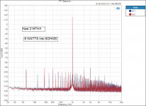
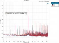
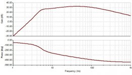
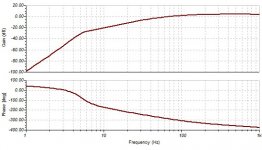
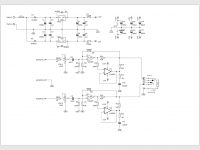
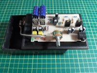
Just for grins here is a sample of a well behaved Full Wave diode bridge power supply in a NAD amplifier. I replaced with new the protection relay and all of the PS capacitors. Plus a not so well behaved example.

Thanks DT

Attachments

  • NAD 216THX FFT.png
    NAD 216THX FFT.png
    67.4 KB · Views: 749
  • FFT Parasound Zamp v.3 5Watts at 8R.PNG
    FFT Parasound Zamp v.3 5Watts at 8R.PNG
    70.6 KB · Views: 729

Measured data on the J105 Nchannel JFET

I've gotten interested in using the JFET-NPN hybrid Darlington connection shown in Figure 1 below. While a standard Darlington has an emitter follower which drives another emitter follower, this circuit has a JFET source follower which drives an emitter follower.

I think I'd like to try the "J105" device in this circuit, and as luck would have it, I bought 100 of them back in August of 2014. I keep a little snip of the shipping bag in my parts drawer, to remind me where and when I bought these units. The J105s came from DigiKey: Figure 2.

So I chose twelve J105 units at random, and put them on the curve tracer. I plotted IDS (vertical axis) against VGS (horizontal axis) with VDS held constant at 10 volts. The slope of this curve is d(Ids)/d(Vgs) which has a special name in circuit design: transconductance. Often written "gm".

The measured data is shown in Figure 3. There's quite a spread in the data!

Simplistic mathematical models of JFET behavior suggest that IDS = Param1 * (VGS - Param2)**2 where Param1 is a gain factor related to the JFET's channel width and length, and Param2 is the "Pinchoff Voltage". "**2" means raised to the power 2, i.e, squared. The data in Figure 3 suggests that the spread of Pinchoff Voltage for these twelve J105s, is about 700 millivolts.

To see this, draw a horizontal line at IDS= 50 milliamps. It intersects the leftmost J105 curve at VGS= -5.7 volts, and it intersects the rightmost J105 curve at VGS= -5.0 volts. A spread of 0.7 volts (!).

If a (very small) sample of just 12 parts, gives a spread of 700 millivolts, I imagine that a larger sample will give a much bigger spread. I hope to measure many more J105s in the coming days, and find the very leftmost curve, and the very rightmost curve. These represent the extremes of the sample and, I hope, they may approximate the extremes of the population of all J105s ever built and sold.

If by some miracle I can find SPICE model parameters which fit these two extreme transistors, then I can simulate circuits using the "best" J105 ever built and also the "worst" J105 ever built. If my circuit design works acceptably with both extremes of J105 then I can feel confident it will probably work acceptably with average J105s that are not so extreme. That's the hope.

Fairchild's datasheet is also attached.

_

Attachments

  • SF_EF.png
    SF_EF.png
    47.8 KB · Views: 1,049
  • DigiKey_Bag_J105.jpg
    DigiKey_Bag_J105.jpg
    71.6 KB · Views: 1,026
  • J105_12units_IDS_VGS_at_VDS_10p0.PNG
    J105_12units_IDS_VGS_at_VDS_10p0.PNG
    57.6 KB · Views: 1,012
  • J105_datasheet_Fairchild.pdf
    J105_datasheet_Fairchild.pdf
    419.6 KB · Views: 138

Phoenix Gold MS-275 distorted output

Hi I'm new here, I'm from Italy 🙂, sorry for my bad english.

I have a PG MS-275, unfortunately it have distorted output sound from the two channel.
Two of the four red led are lightly on and the other two are working fine.
I change the caps and check all the transistor but I can't find any problem, also my external power supply is good.
I try also with another pair of woofer but the problem is still there.

The distorted sound occurs more when the music have bass so I think it's something relate with power but I don't know what it can be.

You have any advice?

Thank you!😀

Source for dual 3.5mm mono jacks?

Despite my extensive google'ing (Newark, Mouser, DigiKey, etc), I can't seem to locate a source for paired 3.5mm mono panel mount jacks such as:

DSuGPOr.jpg


The only ones I've found appear to be intended for direct PC board mounting. I need either solder lugs or socketed like this one:

ZoKF1cK.jpg


This would be used for the 12v trigger(s) in a (hopefully) simple ICEpower'ed amp I'll be assembling.

Suggestions would be much appreciated.

Single power source for 2 chip amps

I'm trying to put together a small, inexpensive setup for mocking up/testing bi-amped 2 way speaker builds. The plan is to use a MiniDSP as an active XO/EQ and send the split signals to 2 chip amps like the ZK-1002L or even raw Tpa3116d2 or tpa3255. I want to put the amps in a single small chassis with a single power supply to run them both, rather than having to use 2 wall wart or brick power adapters with their own cords. Is there a simple plug and play option to suit my needs? I'd rather not build a PSU from scratch. Minimum specs to hit my power needs is 15v 2a but the amps can take up to 24v 5a I believe. I have tried googling dual output power supplies and browsing places like Mouser but I'm really not sure what I'm looking for. Any advice a/o part recommendations would be much appreciated.

Feedback and Gain

Hello everyone, is there a 'simple' way to calculate gain changes with alterations in a feedback circuit?

I have an old Sp8 circuit that takes feedback from through two resistors, one of which is optional to remove for a 10 dB alteration according to the manual. I was wondering if I could reduce by a little less e.g. 5 dB by altering this resistor as opposed to removal.

ARCDB is here (last 3 pages are the circuit I have) and there is a note 5. on the circuit diagram about resistor R27 removal for 10 dB gain.

I have also interpreted that more feedback = worse sound, so want to be careful about how much to temper a very high gain preamp with very sensitive speakers. (It still hums a little too much on standby, and I don't use much of the volume know for full listening levels)

Thanks

B+ & B- toroidal power - noise question (PSRR) for tube amps

I think this is more a power question hence here.

Tube amplifier with B+ and B- from the same PSU, I assume that if we have PSU noise then it would occur on both B+ and B-, thus using both in a push-pull means the output has +noise and -noise along with the signals amplified and therefore cancelling out?

I've not seen this done as much in pre-amp stages from a lot of the schematics - is there any reason for this?

Possible ported enclosure for Panasonic EAS/Matsushita drivers

Hi All,

I have 2 pairs of 16cm EAS / Matsushita drivers that have been sitting on a shelf in my garage for at least a decade. One pair was pulled from some Panasonic speakers like these that I got from Goodwill for like $5.00 but that had cracked plastic housings:

Vintage PANASONIC SB-84 BARREL SPEAKERS MID CENTURY MODERN HI-FI GEAR JAPAN Cool | eBay

I'm not sure where I got the other pair, but probably from another pair of Panasonic speakers.

I recently listened to them in open baffle and found they didn't sound bad at all.
I'm sure these are high Q drivers but, I was wondering if I could do a ported enclosure for them. Something that might get down to 80-70hz.

R/
Jim

Influence of output impedance upon the speaker's resonance

This is speed response of a speaker (Satori MR16) by a 0 impedance generator.

attachment.php


This is the output impedance of APEX AX6.
attachment.php


attachment.php


You can notice that at low frequencies the impedance is negative, I wondered How it can influence upon the speaker. Here is it, notice the phase shift.

attachment.php

pressure response with generator
attachment.php

pressure response with apex ax6
attachment.php

Attachments

  • apex6.2.jpg
    apex6.2.jpg
    47.6 KB · Views: 482
  • imp apex.jpg
    imp apex.jpg
    58.6 KB · Views: 524
  • APEX AX6.JPG
    APEX AX6.JPG
    58.4 KB · Views: 593
  • apexax6.jpg
    apexax6.jpg
    52.2 KB · Views: 494
  • alone.jpg
    alone.jpg
    49.6 KB · Views: 469
  • with apex.jpg
    with apex.jpg
    50.9 KB · Views: 467

OB experimenting driver suggestions?

Hey all, after a many year break from building speakers, i had a listen to my neighbor's setup (not DIY, pair of Pure Audio Project open baffles with a beyma AMT tweeter and dual Morel 10" woofers) and i've caught the bug again, hard... And after listening to some Mono records being played on a pair of speakers and falling in love, i'm going to build a mono speaker to see what it's like.

I've never experimented with full-range drivers before and decided that's where i'm gonna start this time. So was just wanting to fish for some recommendations on drivers to start with/look at.

Going to go OB. Would love to do everything >250hz with a full range driver. But can't decide if i should go 3 or 4" full range and try to get it down to 250hz-ish and cross to bigger driver to get me down to 100hz or so where i'd then cross to dipole W-frames (because i've never tried an W frame and want to try it). OR if I should just go for a 8" full range and run it as low as i can get away with, cross to the W-frames where i can get away with it.

So I'm looking for A) some ideas of full range drivers to consider B) what do you guys think small full range or big?

Also, i'm willing to spend up to about $150 for the main full range driver, but i personally get a lot of satisfaction from using budget parts (the thought of using a Fostex FF85WK for <$50 makes me happy but it's unclear to me how low i can run it)

Oh, and everything will be active with crossovers and any EQ applied via an older minidsp 2x4. My listening tastes are mainly jazz and acoustic music.

thanks a bunch in advance for any ideas, comments, or suggestions!!

SPL Dynamicss-1200D PS Trouble

I received this amp. The owner connected a sub with lower impedance, the amp draws current and switched off.. I want to test the amp, but its not switching on.


On the PS Driver Board is a Jumper, seems like undervoltage release. If i switch that jumper , the amp turns on. Does anybody have a diagram for this. Iam sure, that there was something in the forum, but i cant find it.

Attachments

  • Screenshot_2020-11-05 SPL Dynamics S1200D - AMP-Performance.png
    Screenshot_2020-11-05 SPL Dynamics S1200D - AMP-Performance.png
    974.4 KB · Views: 108

Carver M400 PSU Repair

I picked up a Carver M400 cube the other day. it was blowing fuses. Found a service manual online that is very detailed! following the steps in the manual i found out it had a blown Bridge rectifier for the 25V supply, got that repaired and now i can get it to the point where i raise the voltage on a variac and the triac starts to fire but it is running very rough. looks like the triac is not firing correctly. from what i gather in the SM that at idle I should only see half of each sine wave. that the triac should be cutting off at the peak of each. and what im seeing looks more like a full sine with a glitch around crossover every other sine and the transformer ticks.

changing the triac made no difference so i am assuming that the diac is bad. I cant get it past 60% of line voltage without it drawing lots of current. and adjusting the firing control pot on the PSU board doesn't seem to do anything which i figure is probably normal at this point.

I'm curious why i couldn't use a standard light dimmer adjusted to half sine to fire the transformer just for testing? there wouldn't be any regulation but I could at least test to see if the rest of the amp comes up and runs long enough to verify the problem is in the triac control section. Looking at the schematic that's all this PSU is, is a light dimmer circuit. same exact circuit with the exception of an LDR in place of the pot.


Zc

FS: Tesla P-1011 tonearm

Anyone interested in a tesla P-1011 tonearm ? It was removed from a broken Lenco L450 turntable and has been sleeping in a box for years.

Some data: Tesla P 1101 Manual - Stereo Tonearm - Vinyl Engine

It's in good shape except for two points to fix:
- the outgoing lead is quite short; it probably would be necessary to rewire it.
- one of the small leads on the headshell has lost its connector. They're quite old, it might not be a bad idea to change all the small leads anyway.

The small counterweight isn't on the pics but is of course included too.

Just make me an offer, shipping at cost from Belgium.

630412d1502801377-fs-tesla-p1011-tonearm-img_20170815_141125307-jpg


630411d1502801377-fs-tesla-p1011-tonearm-img_20170815_141143724-jpg

VU (PPM) Meter ONKYO M-5060

Guys,
I really like the way the Onkyo meters work. Fast and sharp response. These meters are the best that I ever seen so far. This is why I decided to build circuit based on this design. Obviously is not only the circuit to ensure this performance but also the meters! I hope you can help me determining the proper meters available on the market. I have TA7318 so I'll try to build similar circuit. (Original schematic attached)
First I am trying to understand how the circuit works and I have coupe of questions that I hope you guys can help me.
1. MJM4558. on the schematic it shows they are running at +21V/-21V.
Why? the data sheet says maximum voltage is +/-18V.
2. Diodes, D1006 & D1008. they are used here to prevent deflection of the
meters after power up. They are then bypassed by the relay that is driven
by the protection circuit. D1006 is 15V zener. Based on the 21V supply at t
the output of the Q1006 the voltage is above zener where the diode starts
conducting so the meter deflection must occur.
3. Q1005, what is the purpose of this transistor? It seems to be
protection from meter moving when the speakers are still off. I don't
understand, the base is driven by the lamp driver. The lamp driver is
driven by the same protection circuit that also drives the relay to bypass
the diodes mentioned above.
To turn of the transistor the base is driven negative -3.6V. which is
impossible it rather be - 0.6V. How could the measure -3.6. I know the
resistors R1047 & R1048 make a voltage divider and will give -3.6V but
only if the transistor is not there. Besides the collector when the protection
circuit is hight so supposingly it should fully turn on the transistor but it
remains floating so the signal will flow from the Q1003 anyway and not
protecting the meter from moving...

Attachments

  • Screen Shot 2020-11-01 at 4.10.10 pm.jpg
    Screen Shot 2020-11-01 at 4.10.10 pm.jpg
    466.8 KB · Views: 444

Marantz PM7200 Can't adjust Idle Current or DC Offset

Thanks for reading me:

After i repaired the speaker protection board of that amplifier, all was ok.

So I then proceeded to adjust iddle current, got it, then DC offset. Oh, bboy.

At that stage, on the left channel, after first seeing normal readings while moving the trimpot to get to the correct setting, suddenly readings were all over the place and did not respond to my turning the trimpot.

I played music to earphones, to find that there was no sound on left channel. Only distorted crackles on peaks.

I took out the board and took out the trim pot, measured it as being ok from end to end and from the moving wiper. Cleaned it anyway and retested as OK.

And, i resoldered 7265 that had broken solder joints. That component was probably the one acting up (relays clicking) when i pushed away the supply wires (touching 7265?) to have access to the trimpot. (BTW why do these (TO126?) stand so high on their legs, wrapped in shrink tubing??) I also reflowed the connector for the supply lines, just to be sure.

I reinstalled the board. The audio is now heard on left channel. Distortion is hard to qualify on cheap earphones and with my old ears and in haste not to blow anything up.

But: i can't adjust either Iddle Current (.2mv) or DC Offset (160mv). Trim pots have no effect. With power off i rechecked that DC offset trimpot and it was still behaving correctly.

I probed the supply lines as deep as i could, including around some transistors (results i should not quote now, but maybe of interest: 7261 is E 53.2V, B -52.7V, E -53V). All seemed normal in my limited understanding of those circuits. I tested in circuit the first components branching out of + and -VB, and double diode tested 7265. I did not probe under the copper shield (housing 7251, 7253, 7255, 7257, 7259) yet.

I hope there is an obvious "classic case" component causing that anomaly, which some knowledgable and experienced person here will point out to me.

I saw that i can easily unsolder that copper shield and probe those components. If someone points me to what i should measure there?

BTW all i have is a digital multimeter. It can test semiconductors. It also has capacitance capability but seems unable to measure >20?uf . To find good units in my NOS stash i rely on reading DC volts, discharge, remeasure DC volts, do long Ohms test, and remeasure DC volts to see if it went up. Served me well to date ;-)

So with that multimeter, can i test transistors IN circuit with the double diode test? i'm afraid to kill them with heat from the iron, but will manage a heat sink (like, my wife will hold the longnose pliers ;-)) if necessary.

Thank you all for your insights and help.

service manual:
https://www.hifiengine.com/hfe_downloads/index.php?marantz/marantz_pm7200_service.pdf /url

SB17CAC burned in : any T&S .frd .zma please?

Hi,
Has anyone worked with the SB17CAC35-8 (or-4) and measured the T&S after few months of use or a strong burning in, please ? Any .frd and .zma known please?

I saw measurments by Audioexcite of the NBAC and the T&S parameters seems to move a lot after burning in vs the datasheet. Would like to know how the CAC version compare in the low end for a small cabinet and if a strong BSC is needed...


Many thanks if any feedback, datas,

Slimline 3U question

I'm working on a project that I'm hoping to use the Slimline 3U chassis in the 350mm size (aluminum panels). I would like to find out the position of the vent slots in the bottom panel so I can plan mounting positions of PCB boards, transformers, etc.

The CAD drawings on the Modushop website don't match the Slimline 2U 280mm chassis that I recently got, so I'm assuming that some changes have been made to the design.

Are the slots on the 3U 350mm chassis baseplate the same as the 2U 280mm, regarding the size and position of the slots relative to the back of the enclosure? If so, I can take measurements off the panel that I have.

Thanks.

which will record better on PC

I have SOTA turntable & Mcintosh C34V pre amplifier. I too have Creative Sound Blaster xfi XD sound unit.
I want to record my songs played through turntable.
is it good to use Mcintosh as preamplifier for MM cartridge then to connect to line input of PC. or use Sound Blaster xfi XD for MM cartridge and directly record in pc.
what will have better recording quality.

Thanks in advance for Guidance.

20 years later, time for a new kit?

Back around aught-one I built a set of the full range Adire Audio MTM kits. Bang-for-the-buck is off the charts, but lately I've had a case of the wandering ear. Their bass response is boy-scout honest, and imaging is decent. I find music passages with loud vocals or brass to be a bit harsh. Jazz, bluegrass and rock are the majority of my listening but few genres are ignored.

Since we can't go to live shows these days, I'd love to recreate as much of the experience as I can at home. I have a fairly small room as my listening space, so giant horn-loaded klipsch-esque rigs are off-limits.

I'm not clever enough to design a speaker but I am a recovering professional cabinetmaker, so the woodworking is second-nature to me. Please let me know if you have any recommendations for kits or plans.

Anti-Vibration Feet

I'd like to find out the dimensions of the Anti-Vibration feet that are offered in the DIYAudio Store. I did a search and could not find any specific information.

What is the diameter and height of the footers (not including the stud)? How long is the stud above the footer? How large a hole is required for the stud?

I want to make sure the footer mounting studs will not interfere with components that I am planning to install in the chassis.

Thanks.

Will this work? Or is it going to suck?

Hi!

I was in the loft recently and I found an old Block Rocker IPA006 by ION. To be honest, the sound always sucked. It was never a Hifi unit, but had a long run time and sound that reached well at garden parties / halls etc. Think 'mobile back of bike' units that people build, but without decent sound 😉 We're talking more than 10 years ago before a lot of the newer lithium powered units like the inter-connectable JBLs. Whilst in the loft, I also came across a couple of Vibe Slick 69.2's. The whole lot is destined for the tip unless I can do something with it. So I got thinking: Could I improve the original block rocker so that it doesn't suck and can once again be useful?

The only real aim here is low cost or I may as well go and buy newer Bluetooth inter-connectable units from [insert manufacturer name here].

The existing circuitry is junk. It's got a transformer for mains and a redundant 30 pin iPod dock. As for the speakers, it looks like a mono setup with a mediocre tweeter and 8" sub. There is a mic input which was handy.

The battery used Huanyu HYS1250 (12v 5Ah) which gave a rather impressive run time of about 12 hours.

My brainstorm idea is this:

1. gut existing circuitry
2. keep sub, ditch tweeter
3. fit vibes to sides of unit (the 69.2's are 2 way)
4. fit a 12V amp such as the TPA3116
5. fit decoder unit for bluetooth/aux and mixer for mic that feed to amp
6. Use better battery (I can find a 12V 12Ah lead battery for ~£20)

So layout is:

Decoder > Mixer > Amp > Left (Vibe 1), Lows (Sub), Right (Vibe 2)

I've been looking around on net and various sources seem to suggest that using car audio is a no go, and that a PA speaker is the way to go, although this would incur extra cost. I suspect the Vibes may be too higher wattage (RMS 135 / Peak 400) for a small amp like the TPA3116?

Questions that you good people might be able to answer:

1. Is this flogging a dead horse? Are the Vibes a bad idea? It's only because they're here and free that I have even considered this.
2. I have read that the TPA3116 ideally needs 24v or it will suck.. this is going to double the cost of the batteries if so and make a possible later internal charging solution more complex. Does anyone have any experience with this at 12v? Or is there a better alternative?
3. Is this all just a crap idea and would I be better off with a PA speaker?

Any and all other input/help/advice is welcome!

Ta Chaps and Chapesses 🙂

Hitachi HMA-7500 Idle current issue

Hi guys,

I'm recapping a Hitachi for a friend. The amplifier was working fine so I took it on. After recap I went to adjust and found the old bias pots are faulty so I replaced them. But now although the bias has dropped from 330ma to around 170ma. The service manual states 200ma.

The problem is when I adjust it, it doesn't make any difference! I checked a few resistors around the pot and a few Zener diodes and they are fine.

Any advice would be greatly appreciated.

Attachments

  • hitachi1.jpg
    hitachi1.jpg
    430.9 KB · Views: 406
  • hitachi2.jpg
    hitachi2.jpg
    484.9 KB · Views: 462

LT spice - how to prevent saving RAW and FFT files

Anyone know if I can prevent LT spice saving RAW, FFT, and TXT files?
When opening folders with the ASC files, there are many huge RAW and FFT files laying there. Is there a way to stop saving those? I have tried going to the save default window and checked off (and on) the various options.
I know it was possible in previous versions. Has this option been taken away on version XVII?
Thnx

What are these burnt element pcb hifonics goliath gx5000d

It is a board that controls the output transistors, the symbols are worn and it tries to find what it is, if someone knew I would be grateful for any suggestions. It is a 14-knife smd integrated circuit

Attachments

  • IMG_20201105_175031.jpg
    IMG_20201105_175031.jpg
    458.3 KB · Views: 122
  • IMG_20201105_105730.jpg
    IMG_20201105_105730.jpg
    594.4 KB · Views: 111
  • IMG_20201105_105727.jpg
    IMG_20201105_105727.jpg
    714.2 KB · Views: 119

Late to scene, is there?

Ok, I ripped my entire CD collection onto an SSD, bought a windows touch screen PC and with only Windows Media Server, have a pretty good server. Of course, it goes to a USB DAC, then to an analog preamp, analog crossover and analog amps. Adding a few SSRs so when the PC powers up, so does everything else. The "boss" demands it to be easy and intuitive.

I do still have a very good CD player that is convenient ( PCM out) and a analog line from my cable box for background music. Easy to make both into USB.

I found a pretty nice PC based equalizer.

What I do not find is a well integrated "preamp" application to tie things together as easily as my analog preamp. Simple touch screen buttons for source and volume. Then buttons to get to the EQ, crossover, and output routing setup. I do not see any particular reason this could not be done. Don't need BT, phones or stuff, but I gather some would.

If such an app existed, I would only need the PC and a DAC for each amp.

Actually, we need a protocol and format to feed the digital stream right to the PWM stage of the power amps bypassing yet another D2A/A2D stage but that is a different question.

Function generator transformer problem

I bought a Thurlby Thandar TG210 function generator from Ebay for £10 a while ago which worked fine until yesterday. After turning it on, it developed a loud buzzing accompanied by a distinctive smell. I opened it up and the smell comes from the transformer, it's not a burning smell as such.


Is it worth replacing the transformer, or will this have damaged the circuits?

Attachments

  • inside.jpg
    inside.jpg
    992.2 KB · Views: 120

Hacked Google home mini to have a line out - weird ground noise issue when no sound.

Hi All,


This is actually my second thread on this. My original one was in Class D, but I know it's more related to some sort of line level issue and thought I might get better help in here.


I followed a tutorial to put a line out on a Google home mini which I am feeding into a class D amplifier board based off a TPA3116. This works brilliantly when there's audio coming from the Google home mini.


The "hack" is basically removing the speaker and putting a resistive divider on it's output to bring the speaker level output down to line level.


However, when the home mini shuts down the audio output as it's not doing anything (I'm assuming it turns off the amplifier to save power when not in use) I get a horrible ground noise hum.


I'm not sure how to tackle this. Someone in the other thread recommended putting a NE5532 preamp between the Google home mini output and the amplifier input. I tried this and it made no difference.


Has anyone any ideas? I'll try anything as I'm getting a bit desperate at this stage.

The amplifier is one of these if it matters:
789446d1571733035-6-channel-tpa3116-dsp-aiyima-tpa3116-amplifier-audio-board-5-1-channel-digital-power-amplifier-board-50w-4-100w-2-jpg


Thanks

Best audio power MOSFET

Hi,

I want to know what is the selection of high power mosfet (N channel) for audio amplifier purpose. Currently I use 2sk 3911 (Toshiba), seems it has high spec (600V, 20A), but very high input capacitance (around 4nF).

Considering another kind of MOSFET to get more clear, nice sound of my DIY power amp, or just to parallel the same mosfet to get more damping factor?

Some mosfet available e.g. IRFP 240 (popular), 2sk 1058 (also popular) etc. The original design is using IRFP 350 hexfet. There are some other mosfets available in my local market (not remember).

Thanks,

Ervin L

Big Mouth Strikes Again

I currently have four 3D printers, and every one of them is failing in one way or another.

Out of frustration, I decided to dust off my K40 laser cutter and try making something.

The idea with this project is to make a Unity horn that has pattern control down to about 500Hz, same as the Danley SH50.

I don't see any scenario where my life allows an SH50 in our living room, so what I did with this project is limit the depth dramatically. The idea I had, is that I can achieve a look that's similar to a Quad ESL if I keep the depth down to a minimum.

YJx86UA.jpg


Here's what a Quad looks like, I'm trying for a look like this.

IZBPG8H.jpg


7UkQW5T.jpg


OCpsu9r.jpg


fp1opJc.jpg


tkLTdbk.jpg


tCnW30e.jpg


All the pieces of the waveguide are laser cut. I used hot melt glue to hold it together long enough to fiberglass some of it. Then added foam to make it sturdier. It will require a lot more fiberglass and more foam to make it ready for prime time.

Also, don't mind the weird Halloween decorations, the kids did that. And no, that roach isn't real 😛

Discover the output capacity of PC linear power supply

I hope I am asking the question in the right forum. I bought recently a second hand audiophile server made by a small Dutch company. I do not have documentation but I could identify immediately that they are of very good quality. The server uses a Jetway embedded low power mini ITX board and a custom-made linear power supply with a toroidal transformer.

As the current CPU is not very recent, my idea would be to upgrade this part of the system in the future. The issue I have is that I don't know if I can go towards a higher power Mobo/CPU. I managed to identify the transformer and it is a 120va 2x12V.

I am new to this stuff and trying to learn, but is there a way I can identify the maximum load the power supply can provide. The current CPU is a Celeron 10W TDP.

May I share my Zen 4

Hello,

I have just finished my Zen4 amplifier and just wanna share it here. 😀

It work with 2 tyrannies as dual mono amplifier, force cooling by low noise fan with tunnel heatsink.

Sound great. It can push my ATC scm11 with the good tonal in mid and high, bass is acceptable. of course I cannot play it very loud, but at my listening level it perform quite good.

Now, I looking for matching preamp. Any suggestion? Should I go for Aleph P? or BZLS? to be not over kill for the power amp.

Big thank to Nelson for his great sharing.

b5F4Pt.jpg


b5FNee.jpg


b5Ff3l.jpg


b5Fhbk.jpg


b5Fkav.jpg


b5F94E.jpg


b5FTQN.jpg


b5FtnV.jpg


b5F1dQ.jpg


b5FKZS.jpg


b5FZPn.jpg


b5Fcmg.jpg

High power single supply amplifiers?

I have started construction of a 6 channel battery powered system (16S, 20Ah lithium ion) and have some TPA3251 based amplifiers from 3e audio on the way as a starting point. A buck converter is used between the battery and the amps to supply their 36V supply.

If this works out well though its likely that I would want considerably more power for subs than the TPA3251 can supply, I am aware of the TPA3255 which would run off a 51V supply (it was out of stock and has higher idle power consumption so I decided to go with the TPA3251 for now), what options are available for higher powered single supply amplifier modules?

I looked at sure electronics/wondom and their higher powered modules (up to 3000W) all seemed to require split supplies.

I'm not interested in amplifiers that can drive ultra low impedance to get their power rating (typical car audio amplifier) as pro audio drivers are only available in 8 or 4 ohms so to get good volumetric efficiency from the system the amplifier should develop maximum power into 4 ohm.

Sony SCD-1

Hello, I am new to this group. I own a SONY SCD-1 SACD player. It has worked flawlessly for years. Today I was trying to play an SACD disc and it will play out of the analog outputs but neither of the digital outputs. The funny thing is it will play a regular CD through the digital or analog outputs. This happens on a SACD "only" disc. On a dual format SACD/CD disc, the player will automatically switch to CD even when I select SACD when I load the disc. Then while in CD mode it will then play Digital or Analog out. Any ideas? Thank you all in advance.

FS: 8x IsoAcoustic Gaia II Isolation Feet

Bought to try and save my huge speaker from being sold as the room interaction was just killing them. Speakers have now gone and I'm off in a new direction. It was a tough ask and I also tried Townshend Seismic Bars, which were not as effective as the Gaia II.

It was just too much to ask of any feet [emoji3525]

These have about 6 hours of action on them and are immaculate. They are as new.

Here's the details:

"GAIA II is designed for floor standing speakers weighing up to 120 lbs (54Kg). Finished in an elegant machined dark chrome metal housing, the GAIA II incorporates IsoAcoustics’ patented design principles to deliver extraordinary acoustic results.

GAIA II provides a high degree of isolation while resisting lateral movement and oscillations to maintain alignment with the listening position. Internal reflections from the hard-supporting surface are attenuated resulting in greater sound clarity and openness.

'The sound stage blossoms to open up a three-dimensional image of natural, spatial sound.'

Optimal results are achieved by installing the GAIA isolators with the logo facing the listening position, or rotated 180 degrees, to align the isolators with the speaker’s motive forces. Lift and place the speakers into position as the GAIA lower isolators will adhere to the supporting surface.

Designed for floor standing speakers weighing up to 120 lbs or 54kg, the GAIA II will provide more openness and clarity, while reducing structural borne noise. The GAIA II has a height of 26mm and includes M8, M6 and ¼-20 thread sizes.

Designed for a wide variety of floor standing speakers with a maximum weight of 120lbs (54kg). Alternative threaded studs provided in M8, M6 and ¼ -20"

Any scepticism I had was certainly vanquished by these things and I wouldn't hesitate to recommend them.

They are practically brand new and are only just a week old.

I won't accept offers on these as I'm already in the hole on them.

£500 delivered in the UK.

If they don't sell, I will put them on eBay when the £1 listings are available and leave them there until they sell, or I'm dead. One or the other.
abdae63feb1cddca31e06faa38cf0efc.jpg
364e270622458f81f2fffac0887281aa.jpg
403ab745c823460479625b64d116c13c.jpg
361a4f324af10bc1985f422b86fe63f5.jpg
e7b0a169e89a4ce2b71f61b79b9e9f4f.jpg
ba9dce51a79390d95ddfa7901dabe958.jpg
4e0ec7e6a1bed4246353c1c3ea00a4fd.jpg
a928911835e797b8220f5ba6a2f88a96.jpg
8084a47d6cf766f0ddd582a880b107d1.jpg

La6500 as headphone driver

Hi
LA6500 power op amp ( 1A output as datasheet says ) by Sanyo has been used for current amplifier in design attached.

In schematic I have used AD826 as voltage Amplifier and gain is about 4 (12 dB) , but after making PCB I replaced it with MC34002 with same gain , because it’s sound better with my Beyerdynamic DT990 pro 250ohm headphone.
Although it’s old Chip for current but drives my headphone easily and has powerful bass , what you think about my design ?
Thank you all 🙂

Attachments

  • A4C4696B-463E-4332-95BE-97AC5C82E8DE.png
    A4C4696B-463E-4332-95BE-97AC5C82E8DE.png
    218.2 KB · Views: 491
  • 6BA53EBD-0696-4003-BFE0-CFBDB60D34B5.jpeg
    6BA53EBD-0696-4003-BFE0-CFBDB60D34B5.jpeg
    189.8 KB · Views: 578
  • LA6500-Sanyo.pdf
    LA6500-Sanyo.pdf
    28.2 KB · Views: 193
  • mc34002.pdf
    mc34002.pdf
    163.7 KB · Views: 215
  • LA6500 HPA.sch.pdf
    LA6500 HPA.sch.pdf
    27 KB · Views: 133

soundcard output z for loudspeaker imp measurements

i measured my cheap soundcards for their output z, and used this calculator for ease: Measuring input impedance and calculating output impedance calculation calculate audio amplifier op-amp how to measure impedance voltage gain total loudspeaker speaker microphone resistance resistor bridging matching test load loudspeaker source resi

this is the result, all measured at 300hz test frequency:

realtek headphone out:

Zout = 37 ohm (with Rload 10 ohm)
Zout = 30.6 ohm (with Rload 47 ohm)

uca202 headphone out:

Zout = 72 ohm (Rload 10 ohm)
Zout = 61.11 ohm (Rload 47 ohm)

uca202 line out:

Zout = 763 ohm (Rload 47 ohm)

umc22 headphone out:

Zout = 32.15 ohm (Rload 10 ohm)
Zout = 29.44 ohm (Rload 45 ohm)

umc22 line out:

Zout = 123.84 ohm (Rload 47ohm)

sb live! headphone out:

Zout = 3.88 ohm (Rload 10 ohm)
Zout = 1.91 ohm (Rload 47 ohm)

i have always thought i get the best impedance measurements results when used my very old sb live!, can the low output impedance be the reson?

Tapatalk can't load posts

My Tapatalk does not load posts since a few days. It does show the list of post titles, but tapping on those titles gives a "loading" wheel, and then a message saying the post may have been deleted by an administrator (sorry, I don't have the exact message because I translated from my German Tapatalk version).

Tapatalk works fine with other forums, so the problem is specific to diyaudio.com.

Is there anything that can be done about this?

Need help with starting up TDA3255

Hey folks, I have been bangin' my head for days now trying to start my 3255. Firstly, I believe I have blown my first IC by slipping the probe and shorting internal regulator output, so all regulator voltages were close to 0 as a result. After replacing the chip, voltages are now ok according to the datasheet, but I am still getting erratic behavior at the outputs.

This is my first 3255 build, so not sure if my expectations are correct, but I believe I should get it working with attached schematics as a minimum.

What I have now after boot, is CLIP_OTW lit all the time. A/B outputs are giving out something that resembles sine wave, and from C/D, only C has sine wave at the output. Any help is appreciated.

Attachments

  • 2020-11-04_173215.png
    2020-11-04_173215.png
    122.5 KB · Views: 299

IRS2092 900w for Subwoofer Dayton Audio UM12-22 Ultimax

Hi, I recently order a Dayton Audio UM12-22 Ultimax to built a seal sub with 2 cubit ft volume. I am currently using a SVS PC12-NSD for home theater and the new seal sub built will be primarily use for music. I listen to music at moderate volume and sometimes at loud volumes but for a short while only.

I am looking to buy a subwoofer amp to power the seal sub and came across a few from China. Below are a few amp under consideration and I do not plan to spend a lot on the amp as its my secondary setup.

One of the is a cheap plate amp that is rated 1000w.
Specifications:
Upgraded version: Add phase adjustment. Automatic standby. 8 tube linkage
Rated output power is 1000W 8 ohms, (you can use it when you connect the speaker directly)
Features: 1. It has been debugged and installed, - it is recommended to push the 8-18 inch 500W speaker) (equipped)
2. Adjustable frequency (40-180), volume adjustment,
3. Full relay protection: start-up delay, DC output, short circuit of the speaker, etc.
4. Advantages of DC optimization system: Provide continuous offset voltage zeroing control for the amplifier, control the DC output potential of the amplifier, expand the low frequency response of the amplifier, and reduce the phase distortion of low frequency signals.
5. The circuit board uses the original disassembled tube, and the design layout is reasonable and the signal-to-noise ratio is extremely high (no noise can be heard without the audio input line).
size:
Net weight: about 3.2 kg,
Gross weight: 3.6 kg,
Main components: 4 pairs of large tube power audio dedicated tube
4 large electrolysis, 1 high-power toroidal transformer.

Price : USD60 but need additional USD20 for external housing cabinet.

O1CN01bvSGPo1chxVTKtYSa_!!131233633.png

O1CN013fyvOS1chxVWEWV4t_!!131233633.png


Anyone have any experience with this kind of amp? Can it drive the UM12-22?

https://img.alicdn.com/imgextra/i3/131233633/O1CN01bvSGPo1chxVTKtYSa_!!131233633.png

3-pin XLR suggestion

I have the following schematic:

y4mjQsk4txuj1Xo0ewzFpDOcAzIcBaLIOTROx-SWrPFvYMvXpNB8N1UcEu2sSbym1s5LERr39Ki7bdBGP1qHF8Ek726QW7qRJ5-4uKYRtrfEwuouY9ZVnV3Fuiki09e7q2sxIv6tt-ztxBm1l-UnPdfqd6RsaMEpiMf-PmtJ0iqqMjgUfnKt8g-yMyHtjvTjAwp


My XLR has the following connections:
Pin 1 = earth.
Pin 2 = hot
Pin 3 = cold
"lip (4)" = is connected directly to the connector case (shield)

I'm using a Neutrik NC3FD-LX which has a seperate 'lip (4)' so i can solder it to pin 1 as mentioned in the schematic.

To me it doesn't feel right because if lip (4) is connected to pin 1 all ground connections on the pcb board are also connected to earth through the xlr connector case. Also for RCA input because they are connected through the 9-pins connector (see schematic).

I have thought about some scenarios:
1) Only connect lip 4 with pin 1
2) disconnect lip (4) from pin 1 and connect lip (4) directly to my common earth point and leave pin 1 connected to the 9 pins connector,
3) disconnect lip (4) from pin 1 and leave lip (4) unconnected because lip (4) is also grounded through the connector case on the chassis case and leave pin 1 connected,
4) disconnect pin 1 and pin 4 completely from the 9 pins connector and connect both pin 1 and pin 4 to my common earth point ?
5) Other options ?

Anybody?

Internal speaker wiring help

I'm building a box with two tweeters, and I want to run these tweeters in parallel. In order to that, I need to take the single positive and negative speaker wire coming from my amp and split it into two positive and two negative wires.

This is a dumb question, but what's the best/correct way to do that? All the searching I've done, there seems to be a number of ways - 3 way connections, some people twist + solder + heat shrink. Tifco has their own thing. I know some speakers let you easily do this, some don't, so I wonder what's the correct way if they don't

Thanks!
Cesar

Stymied by a subwoofer hum...

I recently set up my setup again after a few years in storage (Fostex 168 Sigmas in corner horns, homebuilt triode monoblocks, Benchmark DAC2, Adire Shiva powered sub), and I'm having issues with a hum from the sub.

It's currently plugged into the same Surgex as the rest of the gear - have tried lifting the ground with a cheater plug, doesn't make a difference. Hum is there whether or not anything is plugged into the input.

Do plate amp caps tend to go bad? It seems to be working fine other than the persistent hum - rotating the phase control does seem to make a difference, so I have some more Deoxit on order to see if cleaning that pot cures it. Does anyone have any other ideas? Thanks!

Stereo LM3886 Super Gain Clone PCB

Hello,


I have a layout of a stereo Super Gain Clone PCB. I was wondering if some folks here could take a look at the layout and comment. It separates the signal and power ground as per Bob Cordell's schematic in Chapter 27 of Audio Amplifiers.


I have the complete project in a github:


GitHub - profdc9/SuperGainClone: A stereo layout of Bob Cordell's Super Gain Clone amplifier.


There are two pictures of the layout. One has the ground plane marked, the other does not. The ground plane corresponds to the power "dirty" ground, while the signal ground is wired point-to-point to the various places it is a reference. There are some small breaks in the ground plane to jump tracks. The two channel inputs have separate signal grounds that are joined together by the hum breaker resistors. The channel input grounds should be joined together at the input connectors.


Thanks!

Attachments

  • Layout-GroundPlane.png
    Layout-GroundPlane.png
    135.6 KB · Views: 622
  • Layout-NoGroundPlane.png
    Layout-NoGroundPlane.png
    123.2 KB · Views: 644
  • SuperGainClone-schematic.pdf
    SuperGainClone-schematic.pdf
    144.5 KB · Views: 307

v12 car amp protect mode

my v12 car amp on protect mode
but when it warms up a few mins.
i turn it off and on it will.work good
i removed input and output wires just to check shorts
no good still.in protect mode

found out that i need to turn it on let it sit for few mins on protect mode
after that i turn it off then on it will.work fine.
but if its not used for.hours/days when i power it on stil on protect mode
i just do warm it up.to make it work

is this a soft start issue? caps inside the amp not charging??

Visaton bg20 fullrange and tw6 tweeter in coaxial mount

I'd like to try a coaxial configuration with the 8" Visaton bg20 fullrange and 2" tw6 tweeter in an open baffle for listening near field.
Would a simple 1st order crossover on the tweeter work in this case? Attached are the frequency response of both drivers.
The bg20 seems to have good output to 10 kHz, so I was thinking to cross that tw6 could be crossed at that frequency or a bit lower?

I know there are more complex crossover for these two drivers when used in a bass reflex enclosure, but I was wondering if I can get away with the simplest crossover.
I mention open baffle because I've listened to those in the past and I enjoyed the sound openness.

Attachments

  • bg20_8_fs.gif
    bg20_8_fs.gif
    32.6 KB · Views: 469
  • tw6ng_8_fs.gif
    tw6ng_8_fs.gif
    8.3 KB · Views: 464

Replace Mark Levinson ML-2 with MJ15024/15025 need help

Dear all,

I have just replaced all the transistors(2N5686 and 2N5684) on my pairs of Mark Levinson ML-2 with MJ15024 and MJ15025(matched). The result is pretty stable, I am now trying to adjust the bias voltage to .56V(1A current to each transistor) as instructed by the service manual available on the web. But both units seems very hot, I cross check the bias voltage of other ML-2 with original transistor and they are around .4V....am I setting the bias voltage too high? Anyone have some idea this replacement?

FS: 8 Tang Band T2-2136SA Full Range Speaker Module 2-3/4" x 2-3/4"

Attachments

  • 09F0B71C-7106-4518-B717-04BF9CF64C0C.jpeg
    09F0B71C-7106-4518-B717-04BF9CF64C0C.jpeg
    76.8 KB · Views: 325
  • B7E2150A-2633-4BF2-B9A2-0F0DE6A5F752.jpeg
    B7E2150A-2633-4BF2-B9A2-0F0DE6A5F752.jpeg
    59.5 KB · Views: 323
  • 2A20D34F-5312-4CBF-903B-8DF734C01076.jpeg
    2A20D34F-5312-4CBF-903B-8DF734C01076.jpeg
    73 KB · Views: 313
  • B474A2F9-29A7-4DFB-9E55-D52A80134974.jpeg
    B474A2F9-29A7-4DFB-9E55-D52A80134974.jpeg
    62.1 KB · Views: 339
  • DCB195AF-E077-4B69-AFE6-A3E96FA9D8C3.jpeg
    DCB195AF-E077-4B69-AFE6-A3E96FA9D8C3.jpeg
    65.1 KB · Views: 320

FS: Goldring 1022GX cartridge with new stylus

I'm selling a Goldring 1022GX moving magnet cartridge with a brand new stylus. The cartridge housing is used but I bought the stylus from the Needle Doctor in 2019 and never used. It was a backup cartridge but I've been moving towards streaming and don't need. I have the original stylus box but not the original Grado cartridge box. No hardware or tools included. Shipping free to CONUS. Add 3% to cover paypal fees.

Cost: $200 including shipping to CONUS

Attachments

  • Goldring cartridge pic 1.jpeg
    Goldring cartridge pic 1.jpeg
    186.1 KB · Views: 145
  • Goldring cartridge pic 2.jpeg
    Goldring cartridge pic 2.jpeg
    169 KB · Views: 136

Edge Coating

What do you guys think of this? : edge-coating
Troels says "By adding a proper amount of glue with proper elasticity and resilience and in the right place on the inner side of the surround, the energy coming from the cone can better be absorbed and the result is a more linear frequency response". His graphs are convincing, the downside is "They loose some 0.5-1 dB sensitivity"
However, "The source of material and application technique shall not be revealed"
- so time for some idle speculation: 1: what is an appropriate "glue with proper elasticity and resilience", and 2: where exactly is "the right place ". He sort of answers that with a drawing here: W12CY003 where "part of the inner rounding was made thicker"

As for the goop, I've got a can of "Rustoleum Leakseal - flexible rubber coating which I bought some time ago to try as a cone coating. Unfortunately the nozzles on Rustoleum cans in Aus are rubbish & don't give a consistent spray, so it has to be painted on.
I know Planet10 has been painting stuff on cones for Aeons, perhaps you can comment Dave?

DCX2496 SUM problem

Hi, I have a dcx2496 processor. I would like to know how to correctly output it with the bass signal. As far as I can see, there are two options: the first is the output from one of the Low channels, the second is the output of the SUM of both channels. This is where my problem comes in.

I would like to use a limiter for subs. When testing "dry" on the SUM output, I set the limiter to -20db and it works. At about 70% of the signal power fed to the processor, the limiter starts working. However, the same setting on the "Low" output completely does not activate the limiter, even turning it to 100% does not activate the limiter. On the scale it does not even reach the -20db. I know the difference is that SUM sums both channels into one and we have + 6db there? (if I am wrong please correct me). Can someone explain to me how it should be properly configured (and why so), so as not to blow the bass? 🙂
If there is anywhere to read about it, please link

China Post

My old multi-meter was failing so decided buy a new one.
I found a cheap one online wit ha company called Wish in China.
So purchased it.
After a month it didnt come so tried to get in touch with them but couldnt.
So wrote it off and bought a similar one from the UK which came in a few days.

Five months down the line I got a knock at the door and it was the postman with a parcel. Opened it and a shiny new multi-meter.
Only took 6 months to arrive !
So got two now.
Projects by fanatics, for fanatics
Get answers and advice for everyone wanting to learn the art of audio.
Join the Community
507,765
Members
7,887,482
Messages

Filter

Forum Statistics

Threads
406,178
Messages
7,887,482
Members
507,765
Latest member
aleminx