Hi
LA6500 power op amp ( 1A output as datasheet says ) by Sanyo has been used for current amplifier in design attached.
In schematic I have used AD826 as voltage Amplifier and gain is about 4 (12 dB) , but after making PCB I replaced it with MC34002 with same gain , because it’s sound better with my Beyerdynamic DT990 pro 250ohm headphone.
Although it’s old Chip for current but drives my headphone easily and has powerful bass , what you think about my design ?
Thank you all 🙂
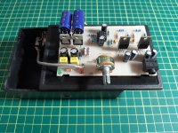
Attachments
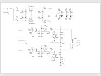
1. Equal load sharing between opamps makes no sense when driving abilities are very different.
2. AD826 is a fairly fast video opamp, while LA6500 seems to be a slugtastic snail (slew rate 0.15 V/µs typ... zzZZ). This is about the opposite of what you want for stability... the buffer should be at least as fast here. You should have seen oscillation had you tested things with a scope (I suspect you don't have one, right?). You'd be far better off with a discrete (single-stage) buffer, or a BUF634 / LME49610 - otherwise you'd have to slow down your gain stage a lot. LA6500 looks like something used as a servo driver in an '80s CD player, not anything you would let near hi-fi audio.
3. MC34002 looks similar to a TL082, except much noisier (a bit of a feat in this day and age) and slightly faster.
This one should not have left the drawing board, I'm afraid. You can do better even with the means of the 1980s. Like Earle Eaton's amplifier, were you to tweak it a little. These days I might even be tempted to make a composite buffer from an opamp + discrete buffer stage.
How did you even end up with parts such as LA6500 or MC34002 to begin with? Recycling?
Thank You so much sgrossklass 🙂
1.Yes la6500 is old chip & at the end of my drawer .I just want to doing headphone amplifier with that & cheated by Sanyo datasheet 🙄 also couldn’t find perfect datasheet . Thank you that guiding it’s For servo driver in CD player .
2.mc34002 is completely old chip , but it’s just has perfect match with this design (I have tried this before with Cmoy , that was noisy )
3.I designed pcb & made it around 2 hours , for more serious designs I order pcb from my local pcb factory.
4. I need help for listening to metal and hard rock , deep bass and vocal in
middle imagining is my favorite
I have tried & build all of this designs :
-Whammy from related threat on diyaudio ( sound is too sharp but really low distortion and great with classic music)
-Cmoy ( ne5532 as op amp with Tps61040 for 3.7 dc dc boost converter to + - 12 volt , low soundstage )
-Irf610 class a headphone amplifier ( nice & smooth sound but not so much power for driving 250 or 300 headphones )
-FiiO e12 with Lme49600 as headphone driver ( the must matched amp for me but midrange is complicated )
-Op Amp + bd139 & bd140 push pull driver ( lack of stability on high volume )
For now I want to design HPA with Tpa6120a2 Composite design with Op amp opa2134, could this be good for metal music and driving high impedance headphone ?
Tnx
Sounds like what you need most of all is some means of performance verification. Just listening may give you hints as to what's amiss, but generally speaking, ears make a poor measurement device. You could use a measurement setup with some Y splitter cabling to attach various real headphone and dummy loads (e.g. 300 ohm, 33 ohm resistors, various C values), as well as an input attenuator to cover voltage levels exceeding maximum recording input amplitude.
So far, your design process seems to have been approximately like this:
Pick circuit topology - implement circuit - listen and evaluate by ear - move on.
It should be more like this:
Pick circuit topology - implement circuit - measure circuit performance - identify potential causes for found anomalies and modify circuit - remeasure etc. (repeat as needed) - listen.
At the end of the day, all you can ask from a headphone amplifier is this:
* a flat frequency response in the audible range
* a given amount of gain / gain selection matching the headphone choice
* enough output for the least sensitive ones (voltage and current)
* low enough noise for the most sensitive ones
* a specific output impedance (often but not always ~0 ohms, but a few headphones deliver their overall most neutral frequency response at decidedly nonzero values - old Beyerdynamic DT831 and 931 models basically needed an integrated amplifier's output with hundreds of ohms, and even today something like a DT880 will appreciate 100 ohms, and e.g. Sennheiser HD800 or HD600 will appreciate a few ohms extra as well)
* THD / IMD(f) <= -80..-90 dBr
* channel separation >>40 dB (preferably, >60 dB) with the lowest-impedance load that the amplifier is likely to be subjected to
* stability even when confronted with (moderate) capacitive loads
* no anomalies even when clipping
What if one of your existing devices already ticks all these boxes? Have you ever considered that you may be asking things of a headphone amplifier that are outside its scope of operation, and should possibly be addressed by EQ instead?
Look at what you have in terms of potentially suitable audio playback and recording devices. If you can afford to buy a $150-ish audio interface outright, that would be a good basis for a setup e.g. using Rightmark Audio Analyzer, but you can make do with something far more improvised if you know what you're doing. There are two basic kinds of setup that will each require different cabling:
a) an audio interface featuring balanced inputs - the Focusrite Scarlett 2i2 is a popular candidate, but e.g. a MOTU M2 features unbalanced outputs right on the box without the need for custom adapters on that side (typical cabling for a 2i2 would be à la RaneNote 110 #10B and #17)
b) an unbalanced output and an unbalanced input, with galvanic isolation provided between them (e.g. audio out on a ~2010-14 laptop on battery, audio in on a ~2005 or newer midrange soundcard in a stationary PC)
There are a few candidates among your existing projects that may very well be able to do the job for your rather limited selection of headphones, if perhaps with some additional work:
The WHAMMY, I suspect, may be a tad marginal in terms of stability. I would suggest removing 100 pF capacitors C2, C7 from the outer feedback loop and placing them between opamp pins 2/1 and 6/7, respectively (22-47 pF may also do). Results between opamp types may also vary (not sure the suggested OPA2604 is such a lucky choice, I might try a plain 4580 or NJM2068 for starters, even a 5532 if DC offset remains acceptable). It could also use a Zobel network on the output as common on speaker amplifiers (maybe 33 ohms + 22 nF or so). Also, there is likely to be some potential for improved distortion driving low-impedance loads if R19/31 values are being reduced vs. R11/R26 (n-channel and p-channel FET input capacitance generally is not equal).
"Op amp + BD139/140" doesn't say very much, and the observed "lack of stability on high volume" could be due to all kinds of things (insufficient bias, lack of some local feedback, poor layout, poor thermal design / bias thermal compensation, ...). Hard to say without having seen schematic + build. That's one where scope testing when driving dummy loads (R and C) may prove insightful. Typical 1.5 A BD139/140 should get at least 30 mA of bias current either way or else they're a bit slow, and 50-75 mA won't hurt. (If you want the long-extinct, less robust but much faster ex-Philips types, NXP only makes these in surface mount any more as BCX/BCP56/53. I am sure an enterprising DIYer could come up with a decent heatsinking solution.)
There's nothing much wrong with an opamp gain stage driving a TPA6120A2 - but can you accommodate this chip accordingly? It has a power pad on the bottom which is supposed to be soldered to a fair bit of copper for heat dissipation, which may not be that easy to do if you don't have a reflow oven (though I suppose preheating the board + a heatgun may get the job done). With average DIY means, it may be better to plan on using the chip upside down, so that you can attach a heatsink on top.
Exactly you are right
Before everything i need some stuff for measuring ( scope , signal generator etc.)
Because i was in a store before as Fiio & sennheiser sales consultant I have good player & headphone for listening but as you said there are deficiency of measurement device on my audio desk.
About op amp + bd139 bd140 I built that from elektor magazine ( translated magazine) and I ordered 4 pieces of layout from PCB factory , and maybe the volume section causes problem about channel separation (pictures provided) .
Whammy has a musically sound for my with some genre like opera or movie soundtracks but when i sourcing this with a Metal music ,its sound is boring.
Tested whammy with bunch of op amps ( 5532, opa2134 , opa2107 , opa2277 , ba4560 , jrc4580 , lm833 , tl062 ) same result received
tpa6120 project , for makaing that i have heat gun & soldering station before. Some forums & sites said it’s a very sensitive chip to layout design so i going to order a 2 side PCB ( all of them will be happen after owning some measurement stuff)
That you again