This is speed response of a speaker (Satori MR16) by a 0 impedance generator.

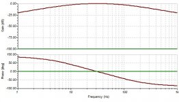
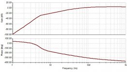
This is the output impedance of APEX AX6.


You can notice that at low frequencies the impedance is negative, I wondered How it can influence upon the speaker. Here is it, notice the phase shift.

pressure response with generator

pressure response with apex ax6

This is the output impedance of APEX AX6.
You can notice that at low frequencies the impedance is negative, I wondered How it can influence upon the speaker. Here is it, notice the phase shift.
pressure response with generator
pressure response with apex ax6
Attachments

Last edited:
I am not sure the output impedance is actually negative.
To ascertain that, you need to plot Vout/Iout with the input shorted and an external stimulus, for example using a current source instead of the load.
Less direct methods are certainly possible, but some thinking and maths are necessary.
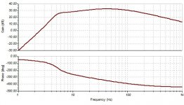
Negative impedance or not, the two poles caused by the output and FB caps certainly cause some peaking in the LF region, straightening the frequency response
To ascertain that, you need to plot Vout/Iout with the input shorted and an external stimulus, for example using a current source instead of the load.
Less direct methods are certainly possible, but some thinking and maths are necessary.
Negative impedance or not, the two poles caused by the output and FB caps certainly cause some peaking in the LF region, straightening the frequency response
I am not sure the output impedance is actually negative.
I am sure: impedance cannot be negative, nor can mass. However, phase can be negative, implying direction.
Even with a 2.2uf capacitor non feedback on the output, as JLH for example, we calculate low frequency cut with the load resistance 8 ohm. But, the LCR character brings the 2.2uf in series resonance, instead of decreasing, it increases the low frequency.

compare to generator driven.
compare to generator driven.
Attachments

If these graphs are supposed to show impedance why is the Y axis labelled 'gain' and calibrated in dB?
0db=1 ohm -20db=0.1 ohm etc. With Tina it is possible to assign the scale but needs lot of adjustments for very low values.
You are certainly mistaken about this.I am sure: impedance cannot be negative
Hello Kokoraintz,
In your sims I see and power amp, and I see some speaker sims. Could you be a bit more specific as to how these amp+speaker plots are generated? Some of the sims are clear, others not. E.G. how have you simmed the speed response? Have you integrated the acceleration of the speaker in question? And how have you simmed the JLH+Cap+Lsp?
In your sims I see and power amp, and I see some speaker sims. Could you be a bit more specific as to how these amp+speaker plots are generated? Some of the sims are clear, others not. E.G. how have you simmed the speed response? Have you integrated the acceleration of the speaker in question? And how have you simmed the JLH+Cap+Lsp?
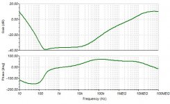
A speaker is an electro-mechanical device which has a mechanical resonator (Fr, Q) activated by an electromagnet. The speed of the voice coil is proportional to the voltage, which results a pass band. The sound pressure of direct radiator, is the derivative of the speed limited in frequency by diameter above which it starts radiating . In sim you need to add a high pass RC to have the pressure response of a rigid piston and you get second order high pass with the same Fr, Q.Hello Kokoraintz,
In your sims I see and power amp, and I see some speaker sims. Could you be a bit more specific as to how these amp+speaker plots are generated? Some of the sims are clear, others not. E.G. how have you simmed the speed response? Have you integrated the acceleration of the speaker in question? And how have you simmed the JLH+Cap+Lsp?
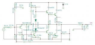
I did not simulated JLH, but I used the DUAL30cv that I diverted the ac feedback taking before instead of after the Cap.
Last edited:
- Home
- Amplifiers
- Solid State
- Influence of output impedance upon the speaker's resonance