During several months now I modified more or less everything in my audio equipment:
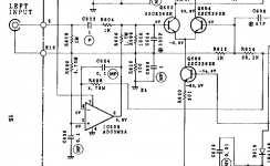
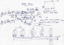
- Quad 303: refurbished and slightly modified
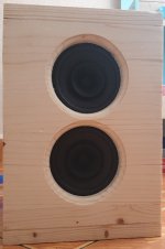
- Tannoy Definition D500: modified crossover and internal wiring
- Audio Server: ripped most discs I own to a tiny Mini-PC running Daphile
- Cables: made analog interconnects (pure silver), USB A-B, and speaker cables (easily dumped my Kimber 8PR for them)
The only item that did not receive any upgrade is my Rotel RC-1570 preamp.
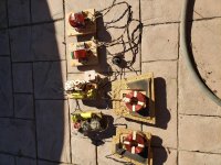
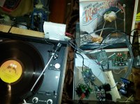
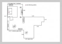
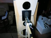
Every single step added a bit to the overall sound improvement. But still ... Have a look at the pic I added, the layout of my living room, which is ... a little bit special. Having mostly glass to the left, and an open space to the right, from listening position my Tannoys show a nice soundstage, but always a bit non-symmetric, uneven. At the moment, the room has no special elements of acoustic treatment.
I experimented one weekend turning the whole situation by 90 degrees to the left, thus blocking the windows and door by audio equipment. It helped a bit, but did not work out from a practical point of view as a living room. So back to what you see on the drawing.
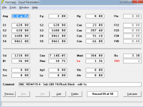
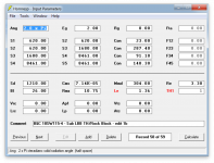
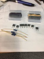
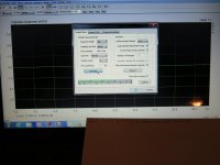
Two weeks ago I learned that BruteFIR filters can be imported to the Daphile server, and that these can be generated by analyzing the acoustic situation using REW. So all I needed was an external audio interface (Steinberg UR12, 69 Euros), a measurement microphone (Behringer ECM8000, 32 Euros), and a 5 meters microphone cable (less than 10 Euros).
My laptop runs under Linux Mint, this is why I chose the Steinberg - it's reported to work well under Linux - and so it does (more or less).
First measuring session was a bit late in the evening - I was tired, but couldn't resist to get started. So my first attempt was to measure both speakers in one run. This certainly is nonsense, but I was tired ... The generated filter had some audible effect, so at least I knew then that my first steps using REW led in the right direction.
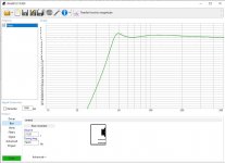
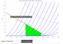
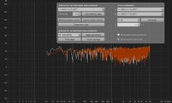
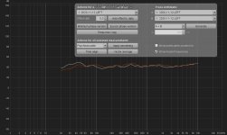
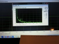
Next day I went for both speakers separately. Same steps, adjusting gains and levels, chose sweeps from 20 Hz to 10 kHz, generated a pair of filters and exported them as .wav files for Daphile. Now the outcome was very different: all instruments got a lot more 'space' around them, were much more clearly defined. The before non-symmetrical soundstage was leveled now, and the sweet spot of listening position had been widened. But still: something's wrong.
By listening to some of my favourite test tracks, I thought most parts sounded much better than before, others left a slightly artificial impression. Just a few examples of what did not work out so well: In Rebecca Pidgeon's 'Spanish Harlem' many sibilants of her vocals appeared much harsher than before, really unpleasant. Same was true for some other female voices like Patricia Barber or Diana Krall. Male voices were not affected so much. Violins, especially in forte parts, appeared really harsh. Hi-hats or cymbals are overemphasized in a way it's sometimes really unpleasant, even at very moderate volumes, while the rest of a drum set could benefit from the filters. All kind of wooden percussion benefited, while metallic percussion often is overemphasized.
So what to do next? I'm a total newbie to REW, so I'll be really grateful for any advice by experienced users.
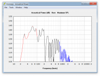
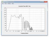
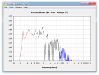
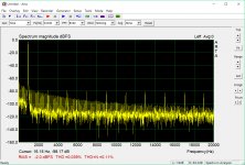
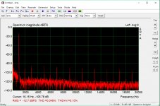
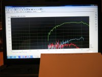
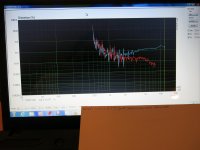
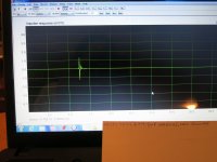
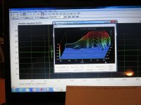
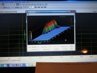
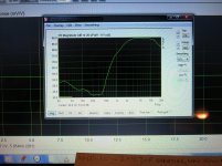
The smoothed SPL curves clearly show that the right hand channel to the open space in red has better linearity than the left hand channel near the wall and windows.
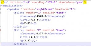
I exported the generated filters as .txt to discuss here.
Questions arising (incomplete list, though):
- Should I limit the filters to less than 10 kHz, so treble remains untouched?
- Should I expand filters to 20 kHz?
- Should I modify generated filters manually?
- How do I read the filter .xml export correctly (What are the 'level' and 'Q' readings about)?
- If it makes sense, can I edit the .xml manually and then generate filters from the modified files (I'm used to working with XML data, btw)?
Any ideas?

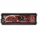
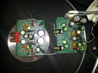
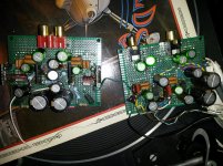
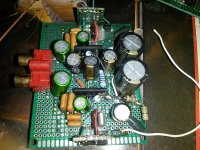
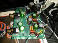
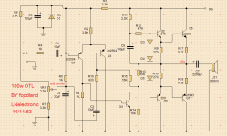
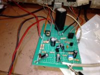
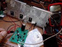
 I thought I might get some help on this forum. So far I've reconnected the cables as pictured. The problem arises when connecting the RCA. There's a loud howl when powering on and the cone starts to move outwards. At that point, a second or so, I turn off the amp.
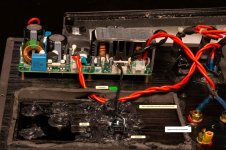


