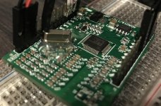
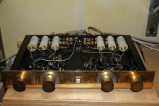
New Passive Preamp project Gray Matter

I recently had a chance to build up a new passive preamp by @audiosteve it's very nice and very straightforward. Works and sounds fantastic. 🙂

It's just a nice little box with an Alps RK27 and three-input selector switch. Front and rear panels are made from PCB material, and with the aluminum clamshell chassis extrusions, the overall package is very solid.

tempImagetyCbQr.gif


tempImageB9gfOq.gif


tempImageIISYhD.gif

Semi Beginner Doing His Best to Eliminate Severe Hum/Buzz

I have the often discussed humming/buzzing amp problem. Yes, I’ve read many of the threads here and elsewhere addressing hum, but none fit my situation squarely enough to solve the problem.

I’ve got 2 Museatex MTR-101 solid state Class A amplifiers fed from a Museatex PA6i preamp. For those who don’t know these, the MTR-101s were a Class “A” amp built in the late 80s. I think they’re fantastic, but they both have a loud hum/buzz that is loud enough to be just audible from OUTSIDE the room with the door closed. This buzz issues from both of the speakers, as well as directly from the power supply areas of both amps.


Here are the details in point form:

Both amps buzz when they are plugged in, but not turned on.

Both amps will buzz, even if they are the only thing plugged in to AC and nothing else (no inputs or outputs are connected).

When I turn them on, the physical hum/buzz from the power supply areas increase minimally to moderately in volume. Then, of course, the speakers also start issuing the same, mostly through the midrange and tweeter.

The house I use them in has a proper and modern grounding scheme. The plugs have been checked for correct ground and polarity. I’m in Canada so 120V 60Hz.

The amps behave like this, no matter where they are plugged in in the house, or even in a neighbouring house

I have replaced ALL the electrolytic caps in the entire system (pre-amp and both mono blocks)

I have replaced the rectifier bridges in both mono-blocks

I have reflowed any suspicious looking solder

DC offset at the amp outlets is only three or four mVs

The amps actually sound very good except for the buzz, so yes, they function as intended, with of course the one exception.

The amps have single-ended inputs

The amps are fitted with 3-prong AC plugs and the AC cable is twisted 3-wire on one of the amps and not twisted on the other amp.

Ground loop may be part of the problem but not the majority. Remember, each amp hums even when plugged in to AC only.

It’s difficult to localize the physical source of the hum in the power supply area but it SEEMS that the toroidal transformer, two covered inductors and a very small transformer on the housekeeping board might all be sources.

I came to suspect DC offset on the AC lines but the problem persists (though admittedly lessened) even now that I have just built and employed three of Sjostrom Audio’s DCT-03 DC traps. (1 DCT-03 for each mono-block and 1 for everything else) All 16 diodes are installed in each.

I’m at my wits end, as the hum/buzz is very loud and I’ve done everything I can think of to address it.

I should note that unfortunately I cannot access or supply schematics for the Museatex equipment.

Any thoughts will be appreciated!


Now an additional but related question. Since I installed the DCT-03 traps the sound has improved in ways other than the slight reduction in hum/buzz. I’m not quite sure what I’m hearing but either the detail and dynamics have improved, or the treble has simply increased. I think I like it over all, but it might also be too analytical and “showy”. Does anyone have an informed opinion as to why these units should have this effect?

For sale (UK only): Rhytmik F12BO w/ A370PEQ3 amp subwoofer

Hello everyone,
Hope everyone is doing well. I'm selling my beloved subwoofer. A rare thing on this side of the pond and am sure there will be interested in a piece of gear like this one. Unfortunately due to its weight and size, needs to be collected. Happy to take visits at any point and no rush.

Details of the subwoofer and asking price, etc here: Bartola website - Rhythmic F12BO sale

Cheers
Ale

Seeking information on the John Koval QUAD ESL mod or how to convert the '57 to 2-way, with no capacitors in the crossover

I wonder if someone on the forum has detailed information on the John Koval Quad ESL mod and would shed some light on how one could re-arrange the '57's crossover/audio transformer connections to arrive at the same or similar configuration. The Koval mod is, to my knowledge, no longer available.

Some background on my plan: Whilst continuing to work on my Acorn build (still ongoing; updates in another thread) I started to realize what an amazing feat it was for Walker to have designed and manufactured the Quad ESL some 70 years ago as a reliable, consistent commercial product. It also began to dawn on me how coherent and musical the ESL '57's midrange really is, and how lucky I was to have enjoyed my '57s for years. Used to take it for granted so when all my '57s finally required a restoration to continue providing services, I kept them in storage without a definite timeline in mind for the rebuild. With the newfound appreciation for the '57 and since I already have the ER Audio re-diaphragm kit, no more procrastination! As for the Koval mod--I first read about it in a reprint of Dick Olsher's 1987 Quad ESL review, and his mention of the mod allowing the '57 "to possess flat response on-axis (within 2dB) from 700Hz clear out to 17kHz" really interested me. Since I have two pairs for rebuild, I plan to convert a pair per the Koval mod if possible, and do a comparison.

The Koval mod is said to convert the '57 from 3-way to 2-way and use no capacitors for the crossover. I presume this means that it feeds the two mid (or tweeter) strips and the treble (or "super tweeter") strip in between with the same signal, and relies on the panel's own capacitance plus the audio transformer's parasitic capacitance for the high pass filtering. However this is just my guess and I have not been able to find more specific information on the Koval mod.

Any information would be much appreciated. Suggestions or ideas are also very welcome.

Ground Loop Breaker, but what's right and what's wrong.

Hi,

I’m living in European and build electronical circuits (power supplies and audio) since about 25 years. I think (or at least hope) I’m familiar with compliance tests and most safety topics to bring a mains powered device to the marked.

Related to audio (my hobby) I had no real issue with ground loops till today, but currently I’m designing a new phono amplifier and like to add a MC option with higher gain. Therefore, I try to do it right and investigate some extra time into the grounding concept. Very often I read, that people recommend ground loop breakers (GLB) as an option. Sure, in a well-designed audio system a ground loop breaker isn’t necessary at all. But I’m tinking about the option to have it in case the system isn’t designed well. 🥴

Actually, I understand the reason why they may reduce some hum, but I don’t understand how they are recommended to build. I read about small resistors between Protective Earth (PE) and secondary GND, because there is no current. I read about ceramic caps, antiparallel diodes, 35A rectifiers as diodes, X or Y-safety caps, but to be honest, I don’t understand why. Placing a safety cap in parallel to a small 100R resistor makes no sense for me, because why “safety” if there is a parallel resistor? I read that 35A rectifiers are recommended, because they have to conduct the false current in case of a malfunction to trigger the fuse before they fail. But this again can’t be a valid safety concept. I actually read, that they recommend to connect PE to chassis using such a GLB! This is against any safety concepts I know and for sure not legal in most countries, but I read about it.

My understanding is, that if the systems chassis in safety grounded, you don’t need a reinforced insulated transformer. The mains transformer itself has to be insulated, so why are these diodes recommended to blow a fuse. It may be wrong, but I thought it’s common and legal to connect the secondary GND directly to PE and it’s not critical related to safety. From a safety aspect, a floating secondary may also be okay, isn't it???

Honestly, I’m confused. I think I don’t need a GLB and try to avoid it and connect secondary GND to safety ground at a star-point or two. But as said, I think about the GLB-option between PE (chassis) and secondary GND, as a fallback option if hum is an issue.

Does anybody understand the safety concept of the GLB. In my understanding a simple resistor with a capacitor should do the same thing. Are the diodes really necessary? If it’s legal to have a floating secondary and it’s legal to connect it to PE, why isn’t it legal to have a simple capacitor between and safe these diodes?

Thanks for any thoughts. I read very much about the GLBs, try to understand and maybe help others (and myself) to make it right. I know that they are built in professional equipment in different manners but what’s right and what’s wrong?

Thank you very much for any helpfull input or discussions to bring some light into this darkness. 🙂

Hawaiian Music Question

Hi everyone!

I’ve been exploring Hawaiian music lately and love its soothing vibe and connection to nature. However, I’m still new to the genre and could use some guidance.

What are some must-listen-to artists or classic tracks that capture the essence of Hawaiian music?

I’m particularly interested in slack-key guitar, ukulele melodies, and traditional chants, but I’m open to modern takes as well.

Any recommendations for albums or playlists to dive into?

Also, if you know of any online communities or resources for learning more about Hawaiian music, I’d appreciate the tips!

Dayton DSP-408 active setup home?

Does anybody have any knowledge of these? I see you can run high level straight into it and then out rca? So can I run in two speakers (3 ways) and out the 4 inputs into an amp?
I’m basically trying to put this before an amp so I don’t have to use individual power for each speaker driver. Not sure if this is possible or not?
Here’s the manual for it.
https://www.daytonaudio.com/images/resources/230-500-dayton-audio-dsp-408-manual(2).pdf
I’m looking to go speakers-dsp-amp-receiver pre outs

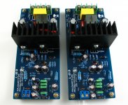
My design L20D IRS2092+IRFI4020H 200W8R

This is me a new design of the AMP. He had since the IR company demo version IRAUDAMP7S-200.

It USES the IRS2092 driver IC, and the IRFI4020H special mosfet output

Its power can do 200 W 8 R (+ 65 V). So I call it the L 20 D.

This version after four times improved. Scrap a lot of PCB to attain my design requirements.

In the test of the wave and test performance he almost and IRAUDAMP7 is same.

And before the same circuit design out, but often appear waveform distortion phenomenon.

I'm glad someone can like this design. It is very small, very beautiful. And a good voice, power is big enough.

Attachments

  • L20D-1.jpg
    L20D-1.jpg
    374.9 KB · Views: 19,624
  • L20D-5.jpg
    L20D-5.jpg
    228.6 KB · Views: 17,917
  • L20DX25.jpg
    L20DX25.jpg
    34.1 KB · Views: 17,033

Beware the power strip

Hi Guys,

I've been using a power strip I bought many years ago. It was just a basic model. I few weeks ago the power switch started arching and the 20 amp dedicated breaker would trip. The strip had an Ashly FTX2001; Chevin 3000a and EV AC1 plugged into it for the main system. I of course replace the strip with an extension cord and 3 socket "T" to plug in the 3 pieces of equipment. I immediately notice a small but definite improvement in sound across all aspects. Soundstage got wider; imaging more in focus; dynamics and bass depth improved some too.

Moral to the story, Make sure all power connectivity is solid and switches are performing properly. Anything loose or that sparks should be addressed ASAP. Power connectivity matters.

Need help with choosing budget DAC

Hi all.
As you can see from my previous post on "Introduction" I am a complete beginner in diyaudio.

I had a question about what DAC to buy for my Classix III by Paul Carmody. Since currently I have a really limited budget, I would like to save as much as possible (<50€). Also, do I also need amp for them?

I tried searching for an answer on both Reddit and DIYaudio, but everyone was suggesting DAC's outside of my price range. Also, I saw DIY DAC boards, but again, I don't know whether they will be enough to power my future speakers.

Thanks in advance for your help!

EDIT: Forgot to say that I could increase my budget, if necessary.

Troubleshooting one Hot Tube 300B

I'll preface this with saying that I'm reasonably new at this, and I'm doing the best I can with a multimeter and what little knowledge I have. But essentially I'm troubleshooting an Elekit 8600 where one of the 300B tubes is consistently running hotter than the other. This is a problem that has (maybe) been happening since I built this amp 6 years ago, but the voltages at a few test points fell within normal fluctuation ranges though a few were a little high, but the amp played fine, and I didn't really focus on it.

That said, I started having issues with distortion, and a channel cutting out occasionally (after 4-5 years), until finally one channel would pop and stop altogether. I would swap tubes from side to side, but ultimately it never seemed to change the performance, and once one of the tubes (I think) became damaged, tube swapping didn't help because if it's the tube AND the amp, it becomes difficult to diagnose. Finally, I just replaced the two 300B tubes, (not the ECC82s or the ECC83) with a matched set. and put them on the amp. I turned on the amp and it sounded OK-ished but I noticed one tube seemed a lot brighter. After a minute or so of playing, one tube was significantly hotter than the other (one was measuring 86F and the other was 136F). I didn't let it keep running because I didn't want to damage the tubes, so I shut it off.

So here are the actions I've taken:

1. Initially when I had the problem, I reflowed the connections for the tube sockets and visually inspected the PCB, problem seemed to be better, but after a while persisted, honestly the problems were intermittent anyway, so not even sure this had an impact
2. Retested all test points. All voltages were fine, except for two fairly close to the channel - these were unusually high, but fell within the 10% range of acceptable according to instructions, but by then, one of my tubes were probably fried so I am not sure of the cause
3. Purchased a matched set of new 300Bs - but in my first try one channel got so much hotter than the other, I shut it off
4. Taken apart the amp, to visually reinspect to make sure that I put it together in the first place, resistors, transistors all in the proper place and orientation.
5. I also visually inspected solder joints - and started doing some continuity tests, but honestly don't know how to do this effectively. I have a Fluke 87 Multimeter which I think is a pretty decent machine, but when it came to resistors, it was hit or miss whether the continuity was registering.
6. I took a multimeter and tested each resistor for the correct value. I realize that IN A PCB, the circuit is going to impact how these measured, and some of the resistors seemed way off, but when they were way off, they were off in pairs, meaning the readings were similar channel to channel - which seems like that means they're correct

I've reached out to the local Elekit partner, and he's working to help out, but honestly, I'd love to learn how to understand this a bit better, and I want to see if there are any other common sense checks I've left out. So here are some questions:

1. How can I test, or should I just replace the ECC82s and ECC83 in the amp?
2. Aside from visually inspecting solder joints (they all look fine) - what else can I do to test components here? I have the schematic but would love directionally some idea of potential areas to chase.
3. Can anyone share a good PCB troubleshooting 101 I can watch/read?
4. What other potentially silly or simple thing am I missing here? Could there be some unwanted issue with any connections downstream? Speaker polarity? Pre-amp?

Question about optimizing PFFB for TPA3245

I am reaching out for comments and suggestions regarding the PFFB and the TPA3245 configurations. The goal is to create a hybrid amplifier with tube input stages and a power amplifier stage using the TPA3245 with PFFB. Further assumptions include an 8-ohm load impedance. I am not interested in a race for output power, as, in practice, achieving peak power on the order of 10W is practically impossible since it can become too loud for others two floors up or down, often resulting in a police visit. Please do not comment on this, it is simply the reality. Playing with a maximum power of 10-15W is more than sufficient for an average apartment with speakers that have an efficiency of around 90-91 dB/W.

Returning to substance, I have already explained why the TPA3245 is sufficient (the TPA3244 would also be enough, but the powerpad facing down complicates things for an amateur hobbyist) and why I have chosen 8-ohm impedance. I will inform you about the tube stages, with the first being a regular RC stage and the second being an inverter with split load. Following that, there will be voltage followers using operational amplifiers, which unfortunately is due to the desire to implement PFFB. The driving impedances for the power stage must be very low and, ideally, identical. This is not achievable for tubes without using large tetrode/pentode tubes, which, in my opinion, defeats the purpose.

The choice of tube type is quite straightforward and obvious — subminiature double triodes 6N28B-V from Soviet Union, which perform excellently at low voltages. They are more readily available than Soviet nuvistors 6S63N. Regarding both types of tubes, due to having a curve tracer, I have characteristics in the interesting range of voltages and currents along with matched SPICE models. The gain of the tube stage should have a reserve of 8-10 dB to meet consumer standard requirements - around 320 mV rms. Again, please do not comment on this, I have signal sources that only provide audio signal at that level. Adding a switchable attenuator to the amplifier input is not a problem, so around 100-150 mV rms and 600-800 mV rms. As mentioned, there should be some headroom since the audio material does not always reach an average level of -6 dB (which is catastrophic), and the tube wears out over time.

Now, another aspect is the modulation frequency for the current switches in the TPA3245. Definitely 600 kHz. The higher, the better, since the cut-off frequency of the LC filter at the output can be higher, thus having less effect on the transfer characteristic in the acoustic range. The higher the switching frequency, the more accurately the highest frequencies are reproduced. I am not concerned about efficiency drops; fighting for 2-5% efficiency is pointless. Of course, there is also one argument against raising the switching frequency: the dead time of the current switches. Circuits like the TPA3116 or the newer enhanced TPA3126 allow switching at even 1200 kHz, and I have not observed significant side effects in practice. I assume that the TPA3245 has a more complex PWM modulation scheme. I remind you that the load impedance is 8 ohms; I am even less interested in 4 ohms.

So the first task is to calculate the values of the LC filter components. I took a Q factor of 0.95 as a starting point, meaning a slight "bump" introduced by the filter. In the case of an open output, a resistor of 2200 ohms will be permanently connected to the output. Before the LC filters, I decided to add LC snubbers (10 ohms and 330 pF). The Zobel networks are somewhat "delicate" (1 ohm and 47 nF) because simulations showed, in my opinion, that there is no need for "stronger" ones.

Another assumption is that the passband for a +/- 0.5 dB deviation should not be worse than 10 Hz - 20 kHz. Such a narrow deviation means that after engaging the PFFB loop, the boost just outside the acoustic band cannot exceed 0.5 dB for a resistive load of 8 ohms. The capacitances at the inputs of the TPA3245 can be high since the gain drop of the amplifier inside the loop for the lowest frequencies will generate additional distortions. Limiting the bandwidth from below will occur before the TPA3245 in the tube stage.

A few tests resulted in the values provided in the schematic.

Schemat.png


In the rectangle bounded by the dashed line, we have a simplified model of the TPA circuit, with two added capacitances (C21 and C22) limiting the passband, which is necessary since the bandwidth of the circuit enclosed in the PFFB loop significantly affects the resulting frequency characteristic and has a significant impact on ringing visible for rectangular waveforms.

I plotted frequency characteristics for several values limiting the bandwidth of the TPA circuit. The overshoot does not exceed 0.4 dB, which I consider a very good result. Another observation is that the overshoot varies, reaching a maximum, and then decreases as the bandwidth of the TPA circuit narrows.

Bode.png

Green, blue, red, cyan, purple, gray => C1 and C22 values: 0.1 pF, 1pF, 5pF, 8pF, 12pF and 20pF.

The next step is to calculate the attenuation of the carrier frequency. I achieved a result better than 32 dB for 600 kHz (34 dB). For full output power of 35W, this means that with such attenuation, the power dissipated on the load is less than 15 mW.

LCdamp.png


Now, regarding the rectangular waveform. I assumed very steep rise times of 100 ns. For 8 ohms, the simulation results are excellent.

Overshoot.png

Green, blue, red, cyan => C1 and C22 values: 0.1 pF, 1pF, 5pF, 12pF.

Now for the 2200 ohm load - no connected speakers.

OversootOpen.png

Green, blue, red => C1 and C22 values: 0.5 pF, 5pF, 12pF.


Up to a certain point, it looks good with negligible ringing, but beyond a certain threshold, unfortunately, we move to persistent oscillations. The same is true for the suggested values of the PFFB loop components provided by TI. Analyzing the PFFB publication for TPA3244/45/50/51/55 leads me to conclude that the capacitance introduced into the simplified TPA model in my simulations does not exceed 10 pF.

Now, returning to the passband, for this range, the passband with a 3dB drop ranges from 80 to 90 kHz with a broader bandwidth of the TPA circuit than what results from the 10 pF capacitance. I remind you that for a 0.5 dB drop, we have a passband above 30 kHz. Is 80 - 90 kHz bad? No, it’s very good considering that the drop at the upper end of the passband is significantly faster than 6 dB/oct. Let's be honest; how many people, mainly men over 40, can hear 15 kHz? I bet for a significant majority, 10 kHz is a challenge.

Finally, I will revert to the tube stage. The operating point of the 6N28B-V tubes at a power supply voltage of 52-55 V can be set so that for the second harmonic, the distortion level is in the range of -40 to -50 dB, and for the third harmonic, it is 20-26 dB lower. The remaining higher harmonics should be at least 36 dB lower than the second harmonic.

I also want to criticize the race for the THD+N value. In reality, it is a race just for the noise level. Let's look realistically at listening with speakers. The background noise level during the day in an apartment does not drop below 40 dB (away from a busy street). 30 dB is realistically at night, it might drop to 25 dB. Below 20 dB, there is no chance. The SNR value means that if we add that to the background level, we are almost at the pain threshold. Moreover, let’s also consider how recordings are made.

That’s all for now. I would like to request some substantive feedback regarding the schematic and the simulation results.

Regarding implementation, ceramic capacitors will be C0G, then U2J, and finally X7R outside the audio path. Decoupling the power supply pins of the output bridge in the TPA circuit will consist of two 4.7 nF C0G capacitors plus one 1uF X7R capacitor. Further from the IC, there will be two polymer capacitors of 680u. A bit further, closer to the power supply, there will be two 330-470 uF polymer capacitors. The snubber will use a C0G capacitor, the Zobel network will employ the defined values, and the LC filter will utilize MKP capacitors. The tolerance for ceramic and film capacitors will be 5%. Coupling capacitors in the tube stage will be MKS. Any ceramic capacitors limiting the upper bandwidth will be C0G. All resistors in the audio path will be MELF 1%. Standard thick film SMD resistors are only defining the operating mode of the TPA and used in the converters. The output filter coils are Coilcraft UA8013-AL (this is a critical component and should not be skimped on).

THT components will be the polymer capacitors because the SMD electrolytic capacitor housings are unfortunately not very durable. Additionally, these MKP and MKS components will be THT as well as the tubes, potentiometer, and power-on relay. This relay is necessary because the switching power supply that will power the amplifier will be an external device. This is the best approach, as bringing the power supply wires into the housing along with a huge mess of interference (inverters in renewable energy installations, inverters in household appliances) is something better avoided.

As for this relay, a high-inrush industrial relay rated for 20 - 24 A won't work because welding of contacts is guaranteed in DC circuits with low ESR capacitors like polymer ones. I use pre-make tungsten relays where a contact rated for 16A can handle an average current of 800A for 200 us. They are not particularly expensive and can still be easily purchased (but may disappear as they were mainly used to switch prohibited light sources like fluorescent lamps, sodium, mercury, or metal halide lamps).

The PCB will be a double-sided FR4 laminate with a copper thickness of 70 um, dedicated to the TPA3245 evaluation board heatsink. The cost is significant; since the components alone will exceed USD 700 for a single board ordered from a reputable company (e.g., Eurocircuits and not from China, since you need to order 10-20 to weed out defects and select a properly manufactured one, and they can also add extra VAT and customs duties in my country), that results in about USD 150.Additionally, there will be a housing plus all this "jewelry" of speaker terminals, knobs, etc. This cost can be criticized, I understand, but if I wanted something cheap, I would buy a cheap product from Aliexpress. Therefore, I do not skimp, and instead of ordinary aluminum capacitors, there will be polymer ones in the audio path.

Pioneer SX-870 Receiver (Broken trimming resistor)

Hi All!

First off, let me say I'm a newb when it comes to repairing these, but I'm working on expanding my knowledge to become better (My apologies in advance).

I have an old broken Pioneer SX-780 that I got a decade ago, that's been on the backburner on getting fixed up until now. Taking a look inside, it does look to have some water damage, and bunch of capacitors were blown. Which is a bummer, because the outside case looks almost mint. Just need to clean the dials from some light dirt. Pretty ironic that the outside case is excellent, but the inside bad..
473307208_10231759047013836_885987280341732901_n.jpg


IMG_2890.jpg


There's some rust and corrosion inside, which I've cleaned a lot of it off the board and most of the components. I replaced almost all the capacitors and now, I got the receiver to boot, and clear protection mode. One of the channels doesn't work at all though. I went to go adjust the the DC offset on the board, and one of the trimming resistors just fell apart. I'm trying to find a replacement for it, but I'm a bit overwhelmed trying to find the right part. Any help would be greatly appreciated!

cm1r8nfk78ee1.jpeg


Taking a look at the service manual, I believe this is the part. Could someone help me find a part? Many, many thanks in advance!!

Part No. Symbol Description
ACP-014 VR5, VR6 Semi-fixed 150k

This is the part I need to replace Here:
broken dc switch.png


Best,

Nater

Greetings from the Texas coast. I'm making a custom mixer/amp/receiver with crossovers/bandpasses/inputs, mids, highs, and a sub

Howdy folks. I taught a few semesters of university level E&M labs in a physics department in another lifetime (when I was in grad school). I've become a pretty seasoned roboticist already, but I'm learning about making audio systems right now. One of my startups (http://indiejamland.com) revolves around music, and so I'm making a custom mixer/amp/receiver with crossovers/bandpasses/inputs, mids, highs, and a sub. It will be portable, one piece, and powered by a car battery with solar charging option.

I still haven't finished transitioning my webserver off of the cloud to a physical server, so it's not super fancy yet -- don't judge me. I'm actually making custom hardware firewalls, while I'm making custom audio electronics, along with 10 or 12 other projects, so don't expect my full attention.

Right now, I'm looking for .mod, .pretty, and .kicad_mod files for tpa3221 and lm386, so obviously, in addition to 100W/200W amps, I'm interested in op amps too. I may need more power later on, too, so what's the next step up from the tpa3221?

Also, I'm curious about alternative suppliers. I was doing business with Mouser Electronics, but they went to the dark side of the force, so to speak. Digikey is a reasonable alternative, but I feel like I'm two-timing my fellow Texans by doing business with them.

Before you think, "aw man, we can't just answer all his questions now -- he'll never need us again..." Realize that I'm also here to network, so I may pop in and out here and there in the foreseeable future. Plus, I'm bound to have other questions later -- not to mention, I may actually be able to help you with your electronics projects.

Hypex SMPS 1200A400 powering up delay and failure

Initially it was 5min delay and it became 30-45 min delay until it would not turn up at all. I suppose some caps have failed.
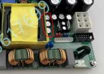
I was reading that people had similar problems with Hypex SMPS and in SMPS1200A700 it is typically c39, c38 caps: 220mf. In SMPS400A400 the problem was also 220mf caps. There is no schematics for 1200A400 so I wander if anybody has similar problem and figured it out what caps need to be replaced? I suspect that these should be caps that I've circled next to the transformer.

Attachments

  • HYPEX bad caps.PNG
    HYPEX bad caps.PNG
    316.6 KB · Views: 46

Affordable TSE PT Option--290CX

Hi,

I just hooked up a TSE-ii 300B that is behaving well with a Hammond 290CX. I'm getting 385-390V B+ with a 5AR4 and a 33uf 1st cap, which was my goal. If you actually download the datasheet, the HV compares a bit higher to the audio series than you might expect because they are tested with 120V on the primary instead of 125V. I imagine the guitar/"lay down" orientation isn't for everybody (and should be isolated from a steel chassis), but they are so common you can save a few bucks.

I found what I think to be 290D2X or other Bandmaster replacement at a used instrument shop for $25 and am going to give that one a try on an SSE board. They don't carry the same price advantage new, though.

Paul

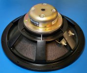
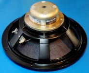
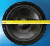
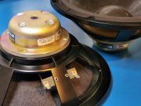
For Sale Meyer Sound ST-410 10" Bass Drivers -Pair

Here's a pair (x2) of lovely Meyer Sound ST-410 10" 4-ohm Woofers that are looking for a good bass cab to really shine or as a replacement driver

I believe they are spares from a theater and appear to be unused, therefore in excellent condition

Superbly made with a cast frame, heavy duty rubber surround, Neodynium magnet, vented pole piece, thick pulp cone with damping coating

The damping material used on the cone tends to pick up dust and the photos amplify the effect. In reality the cones look better than the photos suggest

Used in several Meyer Sound systems including UMS-1P, UPJ-1P

Thanks to the Neodynium magnets they are lightweight, only 2.4kg each

Both drivers have consecutive serial numbers!

Depth is approximately 120mm

Made in USA, rarely seen for sale

I'm thinking USD 550 for the pair plus postage

Cheers, Ralph

Attachments

  • ST6a.jpg
    ST6a.jpg
    296.9 KB · Views: 31
  • ST8a.jpg
    ST8a.jpg
    341.2 KB · Views: 39
  • ST9a.jpg
    ST9a.jpg
    247.9 KB · Views: 35
  • ST10a.jpg
    ST10a.jpg
    213.3 KB · Views: 30
  • ST11a.jpg
    ST11a.jpg
    205.9 KB · Views: 29
  • ST12a.jpg
    ST12a.jpg
    368 KB · Views: 30
  • ST13a.jpg
    ST13a.jpg
    347.1 KB · Views: 35

Need help bass reflex PD18 BR 40

I want to build a bass reflex box for this discontinued speaker, I have been looking for information and I think the bass reflex option is the best fit, but I would like someone to guide me through the design process.

I have been using winisd and hornresp, with winisd I understand myself better, but the port it shows is not front, but rear. So I was wondering if the port speed it shows is real or fictitious, as well as the phase interaction between the port and the driver.

I have also made a small design of a 18 mm birch box, it is the typical L shape with some reinforced areas and the 2 square-shaped ports.

The 2 fundamental questions that come to my mind are:
is the port speed real? since too high a speed implies noises. On the other hand, I read that the port must measure at least 1/3 of the diameter of the driver to avoid distortion, I would like to know if it is true.

The interaction between the port and the driver is not too out of phase in the frequency range to be reproduced.

I will leave more information about the project:
driver precision devices 18 br 40
type of music to listen to: hip hop - drum and bass - reggae from 70s in vinyl record to 2023 digital, also funk, soul... mostly outdoors

Transformer for Soundcraft Spirit M series Mixer with linear PSU - M8 or M12

I have been searching the interwebs with no luck!
Can someone help me with sourcing a transformer for the Soundcraft Spirit M8 mixer.
I attached the schematics for the PSU, unfortunatly there is not much info on the transformer, or i'm reading it wrong

I know the original is torroidal

Aparently the tranformer has 3 secondary windings:
One for the main mixer rails with center tap -17V - 0 - +17V
One for the phantom power 0 - 48V
One for the spdif output 0 - 5V

Thanks for any help!

Attachments

The birth of a DBA system

I am starting this thread, because soon I will move to a new house and set up my horn system again, after a year of living in a rented house with no space to install them. I am fortunate that it will be a dedicated room to enjoy my favorite music in the best way possible, within certain constraints, of course. The properties of the room are not very ideal, as it is a rectangular basement room, with solid concrete walls, ceiling and floor. There is a small room in the back and one access door about halfway. The dimensions are 2,4m ( 8ft) high by 4m (13.3ft) by 10,45m (34.8ft) long. Let's call it a pipe drawer...

The speaker setup is as follows: eight bandpass small subwoofers with single 8" woofers, two lower midbass exponential front horns, two mid-high Le'Cleach horns with BMS 4592ND.
In my previous home, I succeeded to have achieved a proper overall sound, so I know these set of speakers work good together. That room was treated with absorption, diffusion and bass traps at their optimum places, as far as a irregular living room can be tuned.

The new room poses one big challenge among some others: the length of 10,45m (34,8ft) in relation to the other dimensions. So I started to model the room acoustics in REW, trying numerous subwoofer/midbass placements. The multiple subs give me the possibility to use various proven concepts for multisub low frequency applications. While I did not model all variants, none of those concepts are really satisfying in this particular room, but one does. In the end, a Double Bass Array will be the concept of choice to build the system from the ground up.

The advantages from the simulation are clear:

  • Linear frequency range from 30Hz to 300Hz with exellent Group Delay and phase behavior.
  • No resonant behavior of certain frequencies in the bass region and good extension into the lowest frequencies.
  • More even bass sound across the room, as a DBA generates a plane wave without back wall or side wall reflections.
  • Short decay of low frequencies without using extensive bass trapping, i.e. no smearing effects in the bass.
  • No need to fill the room with randomly placed subwoofers (a la Geddes), with the associated cable spagetti.
  • The subs do not take much space and can be placed against the back wall without much cabling challenges.

Disadvantages are also clear, but from a hardware point:

* Need for a DSP and multiple amps, in my case I will need four DSP channels and associated amps. I already own a MiniDSP 8x10HD but the amount of delay is insufficient for this room and I only have two channels left for sub bass. The solution (hurts financially) is to aquire a T.Rack (Thomann) DSP amp, a suitable one would be a 4x250w class D-amp plus DSP build in. This means an extra ADDA conversion after the MiniDSP, as this amp has no digital input, but it is cost effective and for low frequencies, I do not think an extra conversion step hurts too much. With four channels of DSP, one can fine tune the response better than with two channels.

* The back subwoofers do not contribute to the sound as they cancel the sound as soon as the plane wave reaches the back wall, so there are only 4 smallish subwoofers that provides the sound pressure a.k.a. lower efficiency. As I do not listen to ear splitting sound levels, I can get away with this disadvantage. It will take about 100 watts to reach 107dB according to the simulation. The mid-high CD can reach that level with 1W input as the difference in efficiency is about 20dB. No problems here, as I use a flea power 1W tube amp for this horn.

Conclusion up to now: a DBA is the best solution in my opinion when dealing with long, narrow rooms -albeit against considerable costs, but also with savings on the bass trap side.

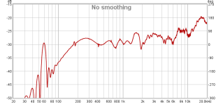
The picture below is an overview of my simulation with both subwoofers and midbass together, I chose to use PSY smoothing in the left graph, to have a simplified view of what is to be expected. The simulation is without any EQ. EQ'ing will of course be preferable, and possible. I applied a modest amount of acoustic absorpion to the room, but fortunately it does not need a lot of absorption, ergo too much absorption will screw it up. I will continue this thread when I am actually moving in and starting to install the system and make measurements of the process.

DBA simulation overview.png


DBA FR_Phase.jpg


DBA impulse.jpg


DBA Group Delay.jpg


DBA waterfall.jpg
  • Like
Reactions: AllenB

Looking for transistor choice advice to implement Catharsis MKII

Hi All,

Currently I'm testing a new output stage design for the amp that I built more that a year ago. It's been occupying my desk for the past weeks, living on a breadboard, trying to find the sweetspot for thermal balance. My plan was to implement most of it with SMD components and use dual monolithic ones where-ever possible. 1206 for resistors that run cool. Hopefully to safe some space for this overcomplicated design and to minimize offset and thermal drift on Catharsis MKII.

2N5551/2N5401 will be FMBM5551/FMBM5401 or NSVT5551 and their complements.
Sadly I have not spotted a BC550 (BC549 on breadboard) dual smd equivalent so far and I was hoping you'd have some suggestions.

I am considering BC847CDW1T1/BC557... or FMB3904/3906 as twin-standins for the BC550/BC560.

Do you know of BJT's that would perform well at low voltages in the place of the BC550/BC560's for Q18, Q17, Q35, Q34, Q2, Q29, Q1and Q28?

Or do you think its best to just sticking with hand-matched through-hole devices?

Many thanks and cheers,

Ruben
Schermafbeelding 2025-01-21 230520.png

Marshall JCM 900 Reverb Drive Circuit Failure

jcm900-preamp.png

I have a Marshall JCM 900 100W tube amp head from 1990 that likely has an issue in its Reverb Drive solid state circuit.

JCM 900 Preamp Schematic from 1990
/\ The schematic of the JCM 900 preamp especially the "reverb drive" section referred to here.


Troubleshooting Progress
While the amp is on and feeding it a 1khz sine wave, an oscope successfully sees the sine wave up to and exiting the V2a preamp tube and can also be seen after the reverb section of the circuit following the dry path.
However, the sine signal is lost below the R23 resistor at the start of the reverb circuit (totally fine above it). Above it is a 400mv peak/peak sine wave. I would expect to see at least a 200mv sine wave below R23.

  1. While the amp is off/caps discharged, in circuit continuity and ohm checks using a DMM on every component in the reverb circuit pass/expected (cannot test the caps but none beep with continuity which is assumed good).
  2. While the amp is on, measuring DC below R23, the DMM is registering about -300mv.
  3. While the amp is on, measuring DC right of R28, left of R26, above C17, left of R27, right of R26 all measure roughly -14.25V.

This leads me to assume that "maybe" either R23 or C16 have issues and should be replaced, but since I am not a guitar amp tech guru, before I start desoldering components and adding even more variables/fail points to this issue, I am seeking some understanding and suggestions.

Questions
❔ Should I only desolder components, test them out of circuit and then get them back in as the only option to pursue?
❔ Can/should I see if R23 is the issue by temporarily jumpering another resistor of same/lower value on top of it in parallel?
❔ Can/should I see if C16 is the issue by temporarily jumpering another capacitor of same/lower value on top of it in parallel?
❔ Can/should I do either of the above by snipping one or both ends of the resistor or capacitor and then jumpering or "top soldering" the left over leads with new components and avoid temporarily having to disassemble the preamp board to under solder them?
❔ Is there a way to replicate this issue with a simulation? See my attempt at an LTSpice rendition of this part of the circuit below.
❔ Is it correct that if the reverb drive circuit was working I should be able to see a > 50mv sine wave through its components on a scope but doing so with DC coupling on the scope since the op amps have 12-15VDC on all of those lines?
❔ What affect does having the reverb tank being connected or not play into any values I would read?
❔ Would acquiring a newer/digital scope provide such a difference that I should seek that first?


Additional Info

JCM900-reverb-drive-ltspice.png

Above is an overview of the LTSpice I attempted to create to provide a simulation of this circuit.
The reverb tank is not an exact replica as it has a much higher input impedance, the reverb pot is fixed R, and I took liberty excluding the channel switching IC7 M5201 and replacing that with a single TL701 (see the actual real link schematic above).
With this simulation, I achieve the expected results below and above R23 and above R20 in the dry area.
While the simulation does see -12V in the op amp areas of the drive circuit, it produces a very small and very distorted ac result which leads me to assume the simulation isn't great.
Thanks to Adrian Immler's post "spice reverb simulation?? This is now possible!" for providing a LTspice of a similar reverb tank.

For extensive additional background leading up to this point, please see this post:
Marshall JCM 900 Reverb Issues
I am aware that it is not ideal and borderline/crosses forum rules about not posting two threads about the same topic; however, when I posted to the valve/tube area I did so since a similar reverb thread was in the solid state area and I have a tube amp and other research implied that one of the more common faults with reverb were related to pre amp tubes, so made the assumption that group was appropriate and now see that forum is more specific to hi fi tube amps.

We meet at last

Good evening everyone.
Decided to finally register here after lots of lurking around as a guest whenever diyAudio pops up on a web search.
Keeping it short, I'm an electrical and automation engineering student in Tampere, Finland. Been a music and audio geek for years. Gigged in a cover band for 7 of them (a third of my life).
Got heavy into the science of audio technology and anything remotely related. Put together a risky design in the form of Dayton RST28F, SB Bianco MW125-8, and Dayton MX15-22. That came out interesting to say the least.

Now I'm trying to build the ultimate pair of living room floorstanding 3-ways. Going good, more on them on a separate post I'm sure.

Anyway, great to join you.
  • Like
Reactions: stv

Introducing Myself

Hi everyone,

I’m Julius, and I’m from Germany. I’ve been building speakers since I was 12 years old, constantly striving to improve my skills and deepen my understanding of the many aspects of speaker design.

I recently finished my degree in Media Technology, where I wrote my bachelor’s thesis on simulation-based loudspeaker development. During this time, I developed a strong interest in BEM simulations, although my knowledge in this area is still very basic. I’m eager to learn more and expand my understanding.

I’m looking forward to having many interesting discussions about DIY audio and learning from the wealth of knowledge in this community!

Best regards

Julius

Greetings from NorCal

I'm a network engineer who is inspired by DIY audio. I'm not sure I have what you would call audiophile ears. I think they're more musician-oriented.

I got started in the DIY space building binary amplitude diffuser/absorbers to treat the walls of my music studio. My focus has shifted of late to updating my stereo equipment on the other side of the house. Everything's analog at the moment, and I'd like to add some high res streaming, so a DAC & streamer have my interest. I'm looking at different designs now as well as whether to build or buy. But I haven't listened to any nice DACS. None. I gotta change that.

I like tinkering and also like the idea of being able to control the quality of the hardware & design. I've been looking different designs, including some from Ian Canada.

Copland CTA 401 transformer

Hi, I bought a Copland CTA401 with 220 volts in Hong Kong. After moving to Canada, I used an audiophile transformer from 110 volts to 220 volts to listen to my CTA401. However, my transformer started to hum and made a very loud noise. Can I change the transformer inside the CTA401 to 110 volts? Any suggestion? I tried to search for the specifications of the existing transformer that was made in Sweden but no luck.

Wiimu A31 module in combination with ADAU1401/1701 DSP

This is for anyone whose interested in building a compact wifi enabled speaker with DSP functionality. I particular have looked around for a long time to find a suitable solution. A raspberry pi is an obvious choice for a wifi enabled media streamer but its cost effectiveness is limited and also the software is often buggy. Moreover, it is difficult to realize whole house audio with multiple synchronous nodes.

A little while ago I stumbled upon the Up2Stream module which is sold by Arylic on Aliexpress and can be had for less than $30,-. The module promises similar functionality to a Sonos system with a wide variety of different sources including airplay via dnla which is a useful function that is in fact missing on sonos. Besides the module can support high-ress playback of 24bit files of up to a 192kHz sample-rate.

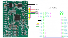
Sadly the module has some limitations with respect to the audio output. Only an analogue output is available with limited audio quality due to the low-cost audio processor that is used on-board of the Up2Stream module. Besides the on-board audio processor is not easily reprogrammable. However, the daughter PCB (A31 module) that is placed on top of the Up2Stream board has a I2S interface which allows for transmission of a digital audio signal to an external DSP without signal degradation.

From some help of the support staff from Arylic I was able to figure out that the A31 module is operating in slave mode with bclk and lrclk being generated by the onboard audio processor of the Up2Stream module. The I2S output of the A31 module is 16-bit with a sample rate of 44.1kHz. All of the audio is thus resampled to this sample rate which is an inherit limitation of the module although I don't think this will be very noticeable. The A31 module can thus be interfaced directly to a ADAU1701/1401 DSP as long as the correct bclk and lrclk signals can be generated.

The ADAU1701/1401 DSP has to act as a master in the i2s protocol which can be done by enabling master mode and feeding back the bclk and lrclk output signals of the DSP to its inputs by connecting MP4 to MP10 and MP5 to MP11. But here’s a bit of a problem, available boards with ADAU1701/1401 DSP chips feature master clocks of 12.288MHz which cannot be broad down to a lrclk of 44.1kHz and bclk of 2.8224MHz that is necessary for the A31 module due to the non-fractional clock divisions of the i2s interface.

I was able to solve this issue on a cheap aliexpress DSP module with a ADAU1401 chip by desoldering the SMD 12.288MHz crystal and replacing it by a through-hole component of 11.2896MHz. With some hot-glue additional support was provided preventing the crystal from falling of due to vibrations or accidental drops. Best of all, it sounds great, much better in my opinion compared to using the analogue interface of the Up2Stream module in combination with the analogue inputs of the ADAU1401 DSP. It does require a slight bit of hacking but it is pretty simple. Best of all, it is cheap to obtain. A DSP solution such as the Hifiberry DAC +DSP can cost about $75,- on its own which does not include the costs of a raspberry pi + sd card. Also, in my experience this solution has much more solid playback functionally without any weird behaviour such as skipping parts of a song. Besides, the power consumption is much lower with an average supply current of just 170mA for the A31 module at 5V.

There is however one slight caveat. With this implementation the software volume control on the source will not work and instead the output volume must be controlled via the DSP. For my use case this is an acceptable trade off but your mileage may vary.

Attachments

  • I2S_connection.png
    I2S_connection.png
    572.8 KB · Views: 2,704
  • IMG_2642.jpg
    IMG_2642.jpg
    426.8 KB · Views: 1,875

For Sale Compression Drivers SB Audience Rosso CDN-65-T

A horn project took a different turn and these drivers are now available. They're new in box and have never mounted. $325 (shipped to CONUS).

They've been difficult to source. Madisound has had one driver (not a pair) in stock for over a year, and no refresh. We sourced them from Solen.ca who is charging a premium for them (325 CAD/240USD each).

Thanks for looking (scroll down),
Thom

bb-comp-drv-01.jpg
bb-comp-drv-02.jpg

Cambridge P40 MKII | issue with sources-switch?

Hi there,

I have a vintage Cambridge p40 mk2 that has these 3 symptoms:

1. from time to time I loose sound in one of the speakers.
Seems the issue is getting fixed after I play with the sources-switch(the blue one from pics inside) .

2. From time to time instead of just loose sound, a lot of distortion is getting applied.
Seems the issue is getting fixed after I play with the sources-switch(the blue one from the inside pics), or/and play with the mono toggle btn.

3. The sound on the left speaker misses some of the brightness. Some high frequenccies are not there, and the sound is kinda dull.
I exchanged speakers, cables, sources etc. The issue is clear if you focus and move the balance from one speaker to the other, or if you play a test "song" to check right and left. With both speakers on, its not easy to feel the difference. Someone can might only feel that the center of the sound is closer to the right(good) speaker.

Overall the sound is wonderful even with the left being duller than it should.

I have it paired with a set of wharfedale Diamond 8.2, 6Ohm 100 watt (I'm worried these are rated at 6Ohms while searching for the Amp I only find 8Ohm recommendations).

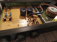
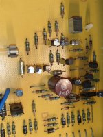
I made one more step forward, and I opened the amplifier trying to get any clear evidence of what might be wrong.
From inside, looks so clear and nice.
I only found 2 really thin packs of coil that seemed they somehow moved away from the ground(yellow-green cable), where they should be connected maybe?

I am attaching photos!
Thanks in advance!

Attachments

  • IMG_20250103_154920.jpg
    IMG_20250103_154920.jpg
    280.5 KB · Views: 44
  • IMG_20250103_154747.jpg
    IMG_20250103_154747.jpg
    386.5 KB · Views: 45
  • IMG_20250103_154719.jpg
    IMG_20250103_154719.jpg
    464.2 KB · Views: 39
  • IMG_20250103_155009.jpg
    IMG_20250103_155009.jpg
    462.9 KB · Views: 38
  • IMG_20250103_154632.jpg
    IMG_20250103_154632.jpg
    446.2 KB · Views: 40

Soft starter with standby

Hi all

I am new to the website but not a total newbie 🙂

I have designed and built a powerfull class A/AB amp with a fat 900VA toroidal transformer and 80mF cap bank. Works well. I use a soft starter as well that works based upon temperature dep resistors and a relay, etc.

Now I am implementing a standby system using Arduino and another relay. It turns off the relay 20 min after trigger voltage is out.

My question is this : is it alright to put the standby relays (two channels for dual power per audio channel) in between the transformer and the cap bank? The relay is rated 30VDC and 250VAC and the voltage is 35VAC. So no issues in terms of AC voltage. Thr issue is in-rush current. Would the cap bank have a large in rush current and burn the elay contacts? Or this is mainly an issue with the xformer which is anyway being taken care of by the soft starter?

I understand the in rush current of the caps depend on the capacitance and ESR but I don't know the ESR values for the cheapo caps which work by the way.

Another easy way is to put the relay on the mains before the soft starter. But then I need an extra xformer to power up my controls.

Thanks in advance for any insights by tbe DIY masters 🙂
Arta

How do you setup your bench power supplies?

Hello all,

So I have had two, two channel power supplies I’ve been using for awhile. A Siglent with two 32V 3.2A channels and a third with 5/3.3V and the other is a two channel Sorensen 75V 2A. I recently picked up a couple Lambda supplies and from what I read they’re top tier. Each supply is 100V 15A.

The manual mentions twisting the output wires together. I’ve never seen anybody twist the outputs of their power supply together. The output of the power supply will have a couple of 18 inch wires coming out of it and they will terminate to a pair of binding posts. Does anyone twist the output wires to theirs? I would think that with only 18 inches it wouldn’t seem beneficial, maybe it means for longer runs?

These power supplies have hook ups for sense wires. Neither of my other power supplies do, how do y’all feel about sense wires? Needed? Would the average hobbyist find them useful?

Lastly, there is an area on the back to hook up the chassis ground of the power supply. I can hook the chassis of the two power supplies together, and then run a hook up by the finding posts. Though I’m thinking I would do without since every single piece of audio equipment on my bench is on an isolation transformer, if I hooked up the ground, it would totally negate the isolation transformer. The section here where it mentions floating the output above ground and limiting it to 100 V for this model, is that in reference to only if I choose to hook up the power supply ground to my device under test ground?

IMG_5207.png


Thank you,
Dan

For Sale B1K Reimagined

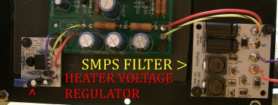
Got it done, since it is the dead of winter and I don't want to shovel snow. This unit is the same but doesn't look like the kit for sale at the DIY Audio store, that's for sure. I used a Grayhill rotary switch on the back, and also included both the SMPS filter, and the Heater voltage regulator. Both of these will be used in future builds. Manley Labs RCA jacks are used as I see them to be some of the best available out there. Same thinking with the power connector. The usual plug in types are prone to trouble, so I am using a screw in type receptacle. Never had a problem with one.
here are some shots, and I am looking to get $500 plus shipping for this guy.

Attachments

  • P1010003 (2).JPG
    P1010003 (2).JPG
    470.6 KB · Views: 85
  • P1010003.JPG
    P1010003.JPG
    337.9 KB · Views: 87
  • P1010002.JPG
    P1010002.JPG
    243.8 KB · Views: 88
  • P1010004.JPG
    P1010004.JPG
    587.7 KB · Views: 79

Post Your Pics of Store-Bought Instruments/Amps Here

Editors Note:
This thread is for pics and descriptions of instruments and amps that are NOT DIY

For posting photos of your DIY Instruments and Amps go here:
Post your DIY Musical Instruments/Amps here!

End Note


Hey would anyone be interested in posting their guitars, amps, other musical instruments? Like on the other forums with the amp pics & info?

DIY USB Ground Loop Eliminator and Filter

Hello

a few months ago the previous designer/engineer of the Ifi Idefender told me that this device applys arround 100 ohms between the usb input and usb output port, and i wanted to DIY something without complicated circuitry

actually now that i think about it im not sure if a dac would work with just the 100 ohms ground, its probably better to always use a external power supply and connect the pc ground trough the resistor (if you completely disconnect pc ground your dac usually doesnt get detected, so some gnd connection is nessecary)

i currently building a small pcb/usb dongle for this purpose

the current layout looks like this:
Screenshot from 2024-03-23 05-58-53.png


Has someone some ideas or sees errors with this?

Current Features:
  • EMI/EDV filter IC on each usb port
  • variable resistance to the pc gnd (not connected, 100 ohm, 1k, 500, 333, 250, 200 (and some theoretical combinations under 100 ohm) (it might be a good idea to make a passtrough switch so A/B testing is possible)
  • 4x panasonic fc 470 uF capacitor bank to improve power, which can be "disabled" for A/B purposes
  • external power supply barrel connector
  • usb power from the pc can be disabled or enabled, depending if you use a external power supply or wanna make sure that the power is not connected

The Phono Stage

I'd like to present here a complete phono stage project. It's been greatly inspired by the original phono cube and if you are interested in the specs, they would be similar (not mentioning the schematic).

In my approach however, I'm using much better parts and much better power supplies. I also wanted to be able to fit everything in a simple 2x3 aluminum tubing enclosure, having the PS integrated with the preamp.

The end result is the phono stage that can compete with basically anything out there, it is so good.

Looking at the board, you may notice that it is same form factor as my both DACs, the size is 2.75 x 8.75"

Attachments

  • Phono1.jpg
    Phono1.jpg
    192.3 KB · Views: 13,488
  • Phono2.jpg
    Phono2.jpg
    193.9 KB · Views: 12,752
  • Phono3.jpg
    Phono3.jpg
    176.4 KB · Views: 12,302

Need a tip for setting up the Kirksaeter RTX400

Hello folks
I have a Kirksaeter RTX400 here, which has now been completely overhauled, but is a bit problematic when setting it up. There is a setting point specified as "level control amplification", but no value is available. I would generally assume that this (and a wattmeter on the output) is used to set the output. However, I don't have a device for measuring power. Is there any advice on how I should do this?
RTX400.jpg

Debugging digital circuit with non repetiive signal

I have a spdif splitter circuit based on 7404 that is not working.
There are 2 stages to this.
1 input spdif to convert to TTL
2.The TTL output from stage 1 goes to 2 TTL to spdif converters, each using two inverters.

For circuit diagram for each stage, see here https://sound-au.com/project85.htm

When I connect a signal generator with a few MHz square wave, I can see on my Tektronix 'scope the output following the input so potentially all good.

When I connect the digital output (spdif) from a streamer and either output to a DAC, the audio is distorted and sometimes stops altogether.

I need to retest but I think the same happened when I used a CD player digital output. To debugI tried to view the spdif signal to the circuit but because it is non repetiive, the scope would not trigger so I could not see the input and output traces clearly.

Maybe I'm using the scope incorrectly?
I do have a digital scope that I think may have storage facility. (shows how ofter I've used that LOL) .. if I can figure out how to use that.

In the meantime any suggestions welcome.

Juma's Head Amp

This is a layout for the Juma's Headphone Amp posted here http://www.diyaudio.com/forums/pass-labs/271926-f5-headamp.html#post4269989 . Some members seem interested in this🙂.
the schematic is attached here again for convenience.
will post gerbers later..😉

edit
schema, left channel here http://www.diyaudio.com/forums/pass-labs/298369-jumas-head-amp-52.html#post4978271
layout stereo pcb here http://www.diyaudio.com/forums/pass-labs/298369-jumas-head-amp-51.html#post4978066
bom for stereo pcb here http://www.diyaudio.com/forums/pass-labs/298369-jumas-head-amp-41.html#post4920913

PSU,
schema and layout for dual rail psu here http://www.diyaudio.com/forums/pass-labs/298369-jumas-head-amp-48.html#post4937986
bom for dual rail psu here http://www.diyaudio.com/forums/pass-labs/298369-jumas-head-amp-41.html#post4920948

Attachments

  • ha-F5-BJTin.gif
    ha-F5-BJTin.gif
    7.9 KB · Views: 4,132
  • Juma HA.png
    Juma HA.png
    53.2 KB · Views: 3,299

Input signal voltage divider versus grid stopper

I have a Wright 3.5 amplifier driving a tractrix horn with 113db Radian 950PB compression drivers. To reduce the volume versus the other drivers, I currently have a voltage divider (47K from 6SN7 grid pin to input and 100K from 6SN7 grid pin to ground) providing a 32% reduction in voltage. I have recently adjusted the 6SN7 plate and cathode resistors and have them where everything is sounding good. The problem is I would like to reduce the volume by increasing the 47K resistor from grid pin to input to be 100K for a 50% reduction in voltage. I understand that a 47K grid stopper will start attenuating high frequencies beyond about 23kh. I have read that a 100k grid stopper will start attenuating high frequencies at about 11kh. My question is whether or not the resistor between the grid and input in a voltage divider is still acting like a grid stopper if both resistors attach to the grid pin. Also, if I change to the 100K resistor will the highs be further attenuated.

Handful of Technics SL-Q5 Issues

Hey folks, as I noted in my introduction I picked up an SL-Q5 recently. The exterior is a little grimy, but all of the functions work, including the queueing, but I’m have a few issues and I think I’m out of my depth (though I’m willing to learn).

Apologies in advance if any terminologies or concepts are flat out wrong:

1) The AV inputs, specifically L, is a little finicky. It seems to need verrrrrry specific placement and weight/pressure otherwise it cuts out of that channel entirely. Not a dealbreaker, but something I’m keeping an eye on — tested on both the original cables and heavier duty replacements.

2) Upon hitting play the tonearm occasionally sets itself on the outside of the record and gets stuck running along the edge, and doesn’t seem to know what to do from there. This is inconsistent and only happens, I’d say, 2 out of 7 times. I’m assuming this has something to do with starting placement?

3) Some records are playing with distortion/slowdown, but most are fine. At least one seems to be due to a subtle warp, but one (formerly owned) album played fine originally on one side but not on the other and now plays a bit off on both, but most curiously I tried an absolutely fresh album that seems quite a bit ‘heftier’ than the others. It’s noticeably thicker, but in perfect condition. It seems to also distort.

I have to imagine this is either a stylus pressure issue or a flutter issue — but I’m so new that I wouldn’t know how to deduce either.

4) I’ve noticed while the queuing does work, it has noticeable impedance in the early phases while holding the < start button. Watching it closely, the first couple sections of the groove scale are much slower than the last 3/4, and at a few points the arm seems to pause then continue. It does also exhibit this behaviour, though perhaps to a slightly lesser degree, using the stop > button.

5) And last, and probably least, I’d love to get her cleaned up down the line. Touch up the paint or at least diminish some of the light discoloration, polish up the cover as best I can, etc etc. Any particular techniques I should be aware of?

Thanks in advance for any guidance on these issues! And I can absolutely grab some photos/video if needed.

2 questions about my quad 405 clone

I built a chinese quad 405-2 clone, powered by +/- 25V
There's no speaker attached, i have 100W 4Ohm resistor instead, where the probe is connected.
I have 2 questions.
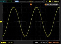
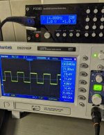
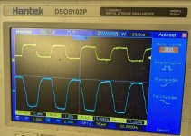
Q1.) Why isn't the squareWave the same on pic #2 as on pic #1 ?
Pic #1 is the signalgenerator -> Oscilloscope, no amp involved at all
Pic #2 : I have a 100k pot as volumeControl , Signalgenerator -> volumeControl -> lineIn on the Amp.
The probe connected after VolumeControl.
Are there better potentiometers to find ?

Q2.) Is there anything i can change/replace on the amp to make it better ?

Attachments

  • square_14khz.jpg
    square_14khz.jpg
    227.2 KB · Views: 45
  • quad405-2_output.jpg
    quad405-2_output.jpg
    153.1 KB · Views: 40

Best way to convert stereo signal to mono signal

Hi, i have some problems regarding stereo to mono coversion that i need for a HI-FI portable speaker.

I searched the internet a lot, but i couldn't find a consistent answer.

So, my question here is: what is the best possible way (circuit) to convert a stereo signal to a mono signal
  • Without causing any additional distortion
  • Without causing artifacts
  • Without causing amplitude drops / imbalances

My idea is to use a NON inverting Op-amp voltage summer with equal resistor values (I need the output to be in phase with the input).

But i dont know if this works perfectly.

Maybe there is no way to convert stereo to mono and a true mono signal can only be generated directly from a computer?

If there is a way to do it in the way i want, let me know.

Thanks in advance.

New Member from New York

Hey, new member from NY, but I've been following this forum for awhile now. I've got a pretty strong interest in anything solid state, though lately there's been a strong urge to try out tubes as well. I've bought quite a few DACs, speaker amplifiers, and speakers over the last few years, but now I'm looking to get back into headphones a little bit so I have options when I want to listen to music/other media. Hopefully going to build my first Whammy in the coming months as well, very much looking forward to it.

On Line Tube Learning for newbies....

Konnichiwa,

As I am one of those to complain loudest when some questions show a lack of basics, how about a thread to collect on-line resources for "TOOBZ NOOBZ"?

I propose these for starters, as being sufficiently and as covering enough ground to allow one who understand basic electronics (8th grade physics really) to understand "TOOBZ"!

RCA Raditron Manual Version 10 from the 1930's, especially pages 5 - 25 in the pdf file....

Bonavolta - Tubes for Newbies

If anyone knows a good on-line resource on basic Electronics (RLC, Kirchoff, Ohm, lentz etc) please post, this could be included as prefix to the above for a "crash-course in electronics".

Sayonara

Cyrus One bias wrong

Hello everyone! I have a Cyrus one , issue 07, i had some caps replaced just as a hobby, then I was thinking to check and adjust the bias. I measured the stock one and had 24.1mV and 29.6mV after 15mins. (Nominal have to be 8-20mV) . I took out the r81 and R82 (130R) and replaced with 180 and 220R for a drop under 20mV. Now the amp it’s working, it seems that lost some low end but it is more precise. My problem is if i measure now across R107 i get 0,21-0,24mV on both cabanele, what have I done wrong?
IMG_2736.png
IMG_2735.png

Attachments

  • IMG_2727.jpeg
    IMG_2727.jpeg
    711.9 KB · Views: 60

Delivery Source wanted for this Cinch female Connectors in special Outline

I want an order address for showed cinch female connectors in special outline, i. e. with additional solder lead for GND connection - go to the attachement (top view of a class-A unity gain preamp based on Andrea Ciuffoli's Power Follower).

The used cinch connectors are from WBT (early 80's) and from this company no longer available since a long time.

Thank you for advices.

Update: WBT tells me by phone, that the follow jacks are the successors:
https://wbt.de/produkte/a/detailansicht/Artikel/nextgentm-cinchbuchse-signature.html
go also to the attachments and to
https://web.archive.org/web/2017031...ailansicht/Artikel/topline-cinchbuchse-1.html
or
https://wbt.de/produkte/a/detailansicht/Artikel/topline-cinchbuchse-1.html
currently overview from WBT
https://wbt.de/english/products/a/kategorien/p/rca-sockets.html

P.S.: this currently offers of RCA/Cinch jacks close to WBT I have just found (July, 18 2023) :

SINNOXX® CB-201 RHODIUM
https://www.dienadel.de/sinnoxx-cb-201-rhodium-cincheinbaubuchse/a-353632238/
Clear Components PREMIUM RCA CHASIS - RHODINIERT
https://www.clear-components.de/cinch-einbau-auswahl/cinch-einbau-rhodium-groß/
Eichmann, FC-TC07 (discontinued - successor available ?)
https://www.vhaudio.com/eti-fr-tc07-rca-socket.html
https://www.audiophonics.fr/en/rca-...-mount-rca-tellurium-copper-pair-p-11934.html
https://www.hificollective.co.uk/phono_sockets/eichmann-phonopod-female-sockets.html
CMC-805-2.5F/816-U/826AG (please note: there are many counterfeits)
https://www.ebay.de/itm/220772577227
http://www.hifizubehoer24.de/Cinch-Einbaubuchsen
http://www.audio-cmc.com/rca-jacks/rca-jacks-p_17.html
http://www.audio-cmc.com/rca-jacks/rca-jacks-p_29.html
http://www.audio-cmc.com/rca-jacks/rca-jacks-p_30.html
CONNEX-75120
https://www.partsconnexion.com/CONNEX-75120.html
FURUTECH FP-908
https://www.furutech.com/2013/01/27/1837/
https://www.justhifi.de/furutech-fp-908-rca-buchsen-4325
https://www.audiophonics.fr/en/rca-...ets-gold-plated-pure-copper-pair-p-10418.html
CARDAS GRFA
https://www.cardas.com/rca-females
https://www.hifi-phono-house.de/hif...erial/cinch-einbau-buchsen/4558/cardas-grfa-s
Don-Audio no Type/Model Naming
https://www.don-audio.com/RCA-Cinch-High-End-PCB-Panel-Jack-Gold-red

Attachments

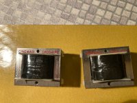
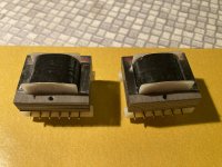
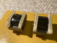
For Sale CineMag CMOQ-4LPC Line Output Transformer PAIR

For sale in EU, here I have a pair of brand new, never used, output, Transformers. These are the 50% nickel versions, I bought them for a Papa project, but went in a different direction. They are €70 each at Don audio, I’m offering the pair for €100 plus shipping.​

CineMag CMOQ-4LPC Line Output Transformer pair.​

1:1 or 1:2 Ratio, Quadfilar Windings, 50% Nickel + 50% Steel Laminations, PC Board Mount​


€100 plus shipping
Paypal friends and family

These will ship from Austria, near Vienna. Please contact me for a shipping quote.

Thanks!
Ps: I also have a pair of interstage transformers from lundahl for sale in this forum if you’re interested. LL1660S.

Attachments

  • IMG_1804.jpeg
    IMG_1804.jpeg
    789.9 KB · Views: 47
  • IMG_1803.jpeg
    IMG_1803.jpeg
    790.3 KB · Views: 39
  • IMG_1805.jpeg
    IMG_1805.jpeg
    795.1 KB · Views: 40
  • IMG_1806.jpeg
    IMG_1806.jpeg
    702.1 KB · Views: 41
  • IMG_1807.jpeg
    IMG_1807.jpeg
    655.1 KB · Views: 37
  • IMG_1808.jpeg
    IMG_1808.jpeg
    739 KB · Views: 41
  • Like
Reactions: ranshdow

A noob's question regarding MFB with a DSP (ADAU1772/1777)

Hey!

So i am kinda interested in MFB but too cheap to purchase a ready-made solution from company like Velodyne. I am also not really good in electronics so making an analog version of an MFB woofer is too much for me.

I found this board based on ADAU1772/1777 on AliExpress.

attachment.php


So it looks like it has line level inputs and line level output.

Can I properly place an accelerometer on a woofer, feed the signal from it to the DSP, get the line level subwoofer audio signal and feed it to another input of this board, then mix the woofer signal with an inverted signal from an accelerometer and basically have an MFB?

I believe, this DSP should be programmed in Sigma Studio. I saw examples of different filter implemented with ADAU1701 and I don't perceive it as something very difficult.

What else is needed for a proper MFB to work? Should signal from accelerometer be amplified before it is fed into the dsp? Any specific kind of amplifier to be used with subwoofer?

I understand that this is extremely noobish, but someone had to ask this kind of question 🙂

Attachments

  • adau.jpg
    adau.jpg
    99.1 KB · Views: 607

My RefSpeaker V2

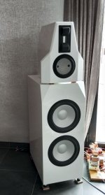
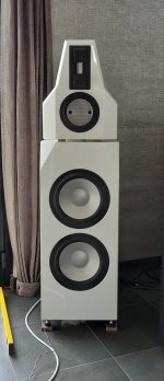
This post is long overdue, I finished version 2 of these speakers a few years ago.
But finally here's the post 🙂

Let me present the version 2 of my RefSpeaker.
All the little annoyances of V1 are fixed, I don't think there will be a version 3 😉

I used the same drivers but with updated cabinets and crossover.
Here's a list of the updates compared to V1:
  • the bass cabinets went from 80 to 115 liter, gives better lower bass and more 25-40Hz output.
  • more bracing in the bass cabinets
  • the bass reflex pipe went from the bottom near back to bottom near front,
    it's 7.5cm diameter and 8cm long, this puts the tuning freq low at 24Hz
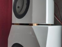
  • For the mid cabinets I went from a 3.5 liter closed box to a 10 liter aperiodic vented cone shaped box, this made a huge update to the sound:
    with the small closed box in the V1 I didn't get the Accutons C173-6-090 to sound completely good, sometimes it sounded nasal, congested,
    I suspect it was due to the backwaves of the cone bouncing around in the small closed box.
    with the new 10 liter cone shape tapered box (45cm long), the backwave is completely absorbed, also thanks to the phenomenal Twaron Angelhair (stuffed 3gr/l), recommended !
    Now it sounds much more natural, open and dynamic.
    Inspiration for the larger cone shaped mid comes from Troels, the venturi vent in the Avalon clone and XTZ divine.
    My findings correspond to those from Troels, see halfway "Mid cab vent",
  • better decoupling between the cabinets and the floor with Sylomer SR110 (0.7kg/cm²), recommended !
  • crossover between woofers and mid a little higher, so the Accuton mid is freed more from the 100-200 Hz duties
  • higher minimum impedance
  • notch filter on woofers to suppress the first impedance peak, gives more equal bass ouput (optional, added switch)
  • better phase integration between mid and ribbon, xo point remains at constant height at different distances.
  • better cabinet damping, the bass cabinet has felt(1.5cm) on all sides and basotect(pyramid 8cm) on the back and top-bottom, the backside an additional 10cm twaron(4gr/l).
    The sandwich felt, Basotect, Twaron works great!
  • Nicer looks with two components polyester paint, 5 layers, lots of work, but great looks 🙂

Specs:
sensitivity: 93db
Freq range: 25-20000Hz
Impedance: 4ohm
Dimensions (WxDxH): 35x52x130cm
Weight: a lot

Drivers (same as in V1):
Raal 140-15DAM amorphous core
Accuton C173-6-090
Alcone AC10HE (two in parallel)

Cabinets:
Separated bass and mid/high cabinets: acoustically decoupled with Sylomer SR110
Cabinets are made of 18mm birch multiplex.
Bass Cabinet:
The bass cabinet is about 115 liters with plenty of bracing and a double/triple front-panel made of 36-50mm birch.
As damping material I used 1-2cm felt on all panels, basotect(pyramid 8cm) on the back and top-bottom.
Bass-reflex pipe is at the bottom, 8cm diameter and 8cm long, tuned for 24Hz.
Cabinet feet are Soundcare superspike with additional Sylomer SR110 pads (0.7kg/cm²)
Mid Cabinet:
The mid cabinet is a 10 liter aperiodic vented cone shaped box, optimized for backwave absorption.
As damping material: 1cm felt on all panels, inside volume completely stuffed with Twaron Angelhair (3gr/l).

Crossover:
The crossover is fairly simple:
3rd order electrical on the woofers to suppress the breakup of the cones, notch LCR on impedance peak (switchable on/off)
2nd order electrical on the mid, no need for pad-down resistors, sensitivity mid matches the parallel woofers + BSC
3rd order electrical on the Raal ribbon.
Crossover points at 230Hz and 3000Hz.
Minimal impedance: 3.5ohm

The quality of the crossover components is important with these drivers, give it crap and you will hear it.
For the woofers I used coils with the lowest possible resistance/distortion: Mundorf MCoil CFS10 iCore (StackCore) 3,9mH + Mundorf L300 0.82mH
The Accuton mid has 12AWG Jantzen wax coil and as caps Mundorf Supreme EVO Oil 47uf + K71-4 polystyrene 3x10uf + Audyn reference 11uf.
For the Raal ribbon I used Audyn reference caps, bypassed with Audyn true copper caps + silver mica, as resistors Isabellenhütte PBH.

What makes these speakers standout is their holographic presentation, excellent separation,
it's like the distances between the lows, mids and highs (instruments,voices) have been pulled out, opened up.
It's easy to hear the differences in soundstage(depth) of different amplifiers, for now the Alpha Nirvana 39 is king 🙂

Regards,
Danny

Attachments

  • Ref2_P10530-150021s.jpg
    Ref2_P10530-150021s.jpg
    512.2 KB · Views: 167
  • Ref2_P90530-150005s.jpg
    Ref2_P90530-150005s.jpg
    474.8 KB · Views: 170
  • Ref2_P90530-150044s.jpg
    Ref2_P90530-150044s.jpg
    180.7 KB · Views: 161
  • Ref2_P90530-165221s.jpg
    Ref2_P90530-165221s.jpg
    283.3 KB · Views: 145
  • Ref2_P90615-101735s.jpg
    Ref2_P90615-101735s.jpg
    366.7 KB · Views: 143
  • Ref2_P90615-101800s.jpg
    Ref2_P90615-101800s.jpg
    271.6 KB · Views: 153
Projects by fanatics, for fanatics
Get answers and advice for everyone wanting to learn the art of audio.
Join the Community
507,574
Members
7,877,709
Messages

Filter

Forum Statistics

Threads
405,764
Messages
7,877,709
Members
507,574
Latest member
Sha1rholder