Hi,
I’m living in European and build electronical circuits (power supplies and audio) since about 25 years. I think (or at least hope) I’m familiar with compliance tests and most safety topics to bring a mains powered device to the marked.
Related to audio (my hobby) I had no real issue with ground loops till today, but currently I’m designing a new phono amplifier and like to add a MC option with higher gain. Therefore, I try to do it right and investigate some extra time into the grounding concept. Very often I read, that people recommend ground loop breakers (GLB) as an option. Sure, in a well-designed audio system a ground loop breaker isn’t necessary at all. But I’m tinking about the option to have it in case the system isn’t designed well. 🥴
Actually, I understand the reason why they may reduce some hum, but I don’t understand how they are recommended to build. I read about small resistors between Protective Earth (PE) and secondary GND, because there is no current. I read about ceramic caps, antiparallel diodes, 35A rectifiers as diodes, X or Y-safety caps, but to be honest, I don’t understand why. Placing a safety cap in parallel to a small 100R resistor makes no sense for me, because why “safety” if there is a parallel resistor? I read that 35A rectifiers are recommended, because they have to conduct the false current in case of a malfunction to trigger the fuse before they fail. But this again can’t be a valid safety concept. I actually read, that they recommend to connect PE to chassis using such a GLB! This is against any safety concepts I know and for sure not legal in most countries, but I read about it.
My understanding is, that if the systems chassis in safety grounded, you don’t need a reinforced insulated transformer. The mains transformer itself has to be insulated, so why are these diodes recommended to blow a fuse. It may be wrong, but I thought it’s common and legal to connect the secondary GND directly to PE and it’s not critical related to safety. From a safety aspect, a floating secondary may also be okay, isn't it???
Honestly, I’m confused. I think I don’t need a GLB and try to avoid it and connect secondary GND to safety ground at a star-point or two. But as said, I think about the GLB-option between PE (chassis) and secondary GND, as a fallback option if hum is an issue.
Does anybody understand the safety concept of the GLB. In my understanding a simple resistor with a capacitor should do the same thing. Are the diodes really necessary? If it’s legal to have a floating secondary and it’s legal to connect it to PE, why isn’t it legal to have a simple capacitor between and safe these diodes?
Thanks for any thoughts. I read very much about the GLBs, try to understand and maybe help others (and myself) to make it right. I know that they are built in professional equipment in different manners but what’s right and what’s wrong?
Thank you very much for any helpfull input or discussions to bring some light into this darkness. 🙂
Last edited:
Actually, I understand the reason why they may reduce some hum, but I don’t understand how they are recommended to build. I read about small resistors between Protective Earth (PE) and secondary GND, because there is no current. I read about ceramic caps, antiparallel diodes, 35A rectifiers as diodes, X or Y-safety caps, but to be honest, I don’t understand why. Placing a safety cap in parallel to a small 100R resistor makes no sense for me, because why “safety” if there is a parallel resistor? I read that 35A rectifiers are recommended, because they have to conduct the false current in case of a malfunction to trigger the fuse before they fail. But this again can’t be a valid safety concept. I actually read, that they recommend to connect PE to chassis using such a GLP! This is against any safety concepts I know and for sure not legal in most countries, but I read about it.
You answer your own question here: it is against safety concepts and quite likely illegal. Or at least unsafe.
My understanding is, that if the systems chassis in safety grounded, you don’t need a reinforced insulated transformer. The mains transformer itself has to be insulated, so why are these diodes recommended to blow a fuse. It may be wrong, but I thought it’s common and legal to connect the secondary GND directly to PE and it’s not critical related to safety. From a safety aspect, a floating secondary may also be okay, isn't it???
Both are means to achieve safe equipment. If you connect your (metal) chassis (correctly) to safety earth then it is a way to ensure safety. Or you can choose to use a doubly insulated transformer to achieve the same safety requirements. But be aware that it is not just connecting the earth to the chassis or use the transformer. You also have to conform to the correct creepage and punch through distances on the pcb and the rest of the wiring.
Does anybody understand the safety concept of the GLP.
Legally there isn't any. It is a band aid to a design that isn't correct. When it goes wrong and there is a real issue, not a single lawyer or insurance company will follow the reasoning of a GLP.
Thanks @Havoc for your quick and great response.
I mentioned lots of questions I give my own answer, that’s right. Allow me to be more concrete. Let’s assume with IEC/UL 62368 as guideline, the cassis is connected directly and with a dedicated screw and crimp to PE. The transformer provides the necessary insulation and all creepage and clearance regulation are considered. All safety capacitors are selected right (X between L and N and Y to PE) as well.
In my thinking, although PE comes with mains, it’s “part” of the secondary. So, with my understanding, it’s allowed to connect secondary GND to PE, isn’t it? And I understand, that a floating secondary will also be fine, looking through the safety glasses if all safety relevant insulations and selections are provided?
If so, it should be okay to connect a simple resistor and capacitor between secondary GND and PE? This will provide the GLB functionality. X or better Y-capacitors are not necessary and the diodes or 35A rectifiers makes no sense, isn’t it? Or do I still understand something wrong?
There's a discussion about it, as an example.
https://www.diyaudio.com/community/threads/ground-loop-breaker.299811/page-2
https://www.diyaudio.com/community/threads/ground-loop-breaker.299811/page-2
In my thinking, although PE comes with mains, it’s “part” of the secondary. So, with my understanding, it’s allowed to connect secondary GND to PE, isn’t it? And I understand, that a floating secondary will also be fine, looking through the safety glasses if all safety relevant insulations and selections are provided?
If your transformer is double insulated you can leave the secondary floating when respecting all spacings between your secondary and any touchable part according to the voltage that can be maximally on those parts with a single failure. But if not (and this means it is not marked with the double square) then you need to connect secondary to PE or design the whole thing . But it is not specified what or where. So you can connect the GND to PE. At the star or somewhere else. Or even V+ to PE like in telephone circuits. You should really take the Low Voltage Directive into consideration. And then specific regulations according to the device.
It has been a long time since I have been involved in designing commercial circuits (or worse, medical stuff). So the regulations can have changed. But I don't think any DIY device will pass such testing unless by accident.
This is a can of worms when you open it.

Thanks’, this helps me very much. I thought a reinforced insulated transformer isn't necessary if your chassis and all touchable conducting parts are connected to PE? Is it still okay to connect GND to PE without reinforced or double insulation (because PE is the first safety barrier)?
I’m pretty sure that this “basic thinks” are still the same today so I’m glad to read your opinion and highly appreciate it.
I’m pretty sure that this “basic thinks” are still the same today so I’m glad to read your opinion and highly appreciate it.
Reinforced insulation is not the same as double insulated. So yes, if you connect PE to chassis then it is not needed to have a double insulated transformer. It is when you do not have a double insulated transformer that you have connect it. And with a reinforced transformer as well because that is not enough to leave the PE connection to chassis out as it is only a single insulation (but better than strictly needed).
Reinforced means just that the insulation is more than basic. That is not the same as double insulated. Double is literally that: there are 2 separate ways of insulation and each of them is able to protect you to the standard. In case of a double insulated transformer, if one of the insulations break down you are still fully protected. In case of a reinforced transformer breaking down, there is only a single barrier. If that breaks you are exposed.
Reinforced means just that the insulation is more than basic. That is not the same as double insulated. Double is literally that: there are 2 separate ways of insulation and each of them is able to protect you to the standard. In case of a double insulated transformer, if one of the insulations break down you are still fully protected. In case of a reinforced transformer breaking down, there is only a single barrier. If that breaks you are exposed.
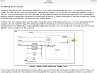
I’m not sure whether or not this addresses your confusion, so my apologies if it doesn’t, but the purpose of the GLB diode-bridge is to conductively (galvanically) keep the signal/power ground and the safety/chassis ground isolated during normal operation, while maintaining high-voltage shock protection should the mains voltage defectively appear on the chassis. The diode-bridge effectively does this by not conducting unless there is more than a 2 diode voltage difference (~ 1.3V) between the signal/power ground, and the safety/chassis ground.
In normal operation, there will be much less than 1.3V difference between the signal/power and the safety/chassis grounds. A shock fault condition would result in more than a 1.3V difference between the grounds, causing the diode-bridge to forward-bias and current clamp the fault condition on the chassis to the safety ground, and thereby blow the mains fuse and switch off the mains input voltage. A clever, and inexpensive solution, actually.
In normal operation, there will be much less than 1.3V difference between the signal/power and the safety/chassis grounds. A shock fault condition would result in more than a 1.3V difference between the grounds, causing the diode-bridge to forward-bias and current clamp the fault condition on the chassis to the safety ground, and thereby blow the mains fuse and switch off the mains input voltage. A clever, and inexpensive solution, actually.
Attachments
Last edited:
Okay, I see. You mean, that you don't need a double or reinforced transformer if you have connected the chassis to PE, but you have to connect the secondary to PE as well, because in case of a broken barrier in the transformer, the secondary will be connected to mains.
If you like to have a floating secondary, you need a double insulation and with other words, a GLB is only allowed in combination with a double insulated transformer?
I understand, that reinforces and double insulated are not the same, but I thought the additional requirements related to insulation, creepage and clearance will make a floating secondary possible as well. Thanks for your clarification.
A clever, and inexpensive solution, actually.
Many thanks for your input, @Ken Newton. Yes, I have the same understanding related to signal and reduction of hum. But as @Havoc said, it can be a safety issue if you do not choose the right insulation system.
If the manufacturer of the device decided to add GND to PE in their safety concept and you add that GLB, the initial safety concept is changed and depending on the insulation system, it’s not legal to do it like that. The fuse may drop because of those diodes, but will the new system really comply to any safety standard. I'm not sure.
As is stated within the circuit diagram, you need to know your local electrical safety regulations if you're constructing A.C. mains connected equipment.
Most power transformers are single-insulated, and provide a first level shock protection from internal device fault. Double-insulated transformers have a redundant insulation level, in case the first insulation fails. For example, a hand-held hair drier featuring only a 2-prong power cord, even though it might be used around water environment. In the U.S., double-insulation frees device manufactures from having to provide shock fault protection via a chassis/safety ground and 3-prong power cord.
Most power transformers are single-insulated, and provide a first level shock protection from internal device fault. Double-insulated transformers have a redundant insulation level, in case the first insulation fails. For example, a hand-held hair drier featuring only a 2-prong power cord, even though it might be used around water environment. In the U.S., double-insulation frees device manufactures from having to provide shock fault protection via a chassis/safety ground and 3-prong power cord.
You are right, but retrofit can be an issue without knowing the initial insulation system, I guess. If you design your own system you have to know this, right. The provided link says everything you need to know, but sometimes it's better to have a second opinion. Thanks for your input.
Anyway, I have seen lots of chargers with a reinforced insulation but connectors are touchable and connected to secondary GND. Actually I'm wondering why we don't have the same issue there? but maybe that's the wrong place to talk about chargers, isn't it?
Thanks guys for your quick response!
Anyway, I have seen lots of chargers with a reinforced insulation but connectors are touchable and connected to secondary GND. Actually I'm wondering why we don't have the same issue there? but maybe that's the wrong place to talk about chargers, isn't it?
Thanks guys for your quick response!
Interesting information here:
https://fiduspower.com/news/understanding-iec-appliance-insulation-classes:-i-ii-and-iii
Unfortunately it confuses me more than it helps. 😵
https://fiduspower.com/news/understanding-iec-appliance-insulation-classes:-i-ii-and-iii
Unfortunately it confuses me more than it helps. 😵
Thanks @Dieter Geissel, do you know what they recommend related to insulation and PE connection on the secondary side? My understanding is, that IEC62368 is the new safety standard for European and some external counties related to that, but it may refer to VDE0100. I'll have to check this later, maybe that I'm wrong. UL62368 is the related standard for the United States.
When you look at commercial equipment, you see that almost all of it falls in one of these categories:
1. Consumer stuff: unbalanced audio, double insulated, no protective earth
2. Professional and semi-professional stuff: balanced audio (hopefully AES48 compliant), single insulated, protective earth
Some special cases excepted, combining protective earth with unbalanced audio connections is asking for hum, unless you use illegal tricks such as ground loop breakers.
Mmh, but what's the way to do it right. I mean, it's a DIY forum and especially at home in a living room where familie will be most of the time.... safety is very important. Having an headphone amplifier in mind... and a broken transformer. 😳
Speaking of safety and family and stuff… look at one of the biggest tech company in the world, apple.
Try to touch their aluminium macbook connected to the mains via 2pin adapter(no earth) and then touch something earthed. Simple example: handle you laptop in hands or chest and then lean your leg(s) over grounded PC case 😀
You will be surprised this pass EU safety regulation… and its just tip of the iceberg.
Last edited:
Mmh, but what's the way to do it right. I mean, it's a DIY forum and especially at home in a living room where familie will be most of the time.... safety is very important. Having an headphone amplifier in mind... and a broken transformer. 😳
You could design it to be class II (with double or reinforced insulation and no protective earth), or try to design it with balanced or quasi-balanced connections in the spirit of AES-48, or use protective earth on only one piece of equipment so it doesn't cause ground loops, or try to minimize the loop areas formed by the signal ground wiring and protective earth wiring.
Getting back to the moving coil cartridges from post #1: the cartridge is usually insulated from the rest of the turntable, so it should be possible to hook it up to an earthed amplifier without causing ground loops.
@Wiliks, you may be right, but we are talking there about leakage current, I guess. This is another issue and most of the time they use ways to big Y-capacitors to fix there EMI issues instead of looking for the source of the interference.
It's another situation if the transformer fails and there is a short between primary and secondary. If there's no RCD and you touch the output, the fuse will allow lots of current before it break.
On the other hand, a lot of chargers I have seen in the past are designed with a reinforced transformer and a floating (or capacitively connected) GND to PE. And they pass safety compliance tests. Looks like I have to think about this in more detail.
Anyway, I don't like to design with decisions and selections like:
But actually I'm not sure what's legal and what's not.
I understand @MarcelvdG that unbalanced audio and protective earth will most of the time generate hum. As I'm currently designing a high gain MC phono amplifier, it's calling for hum issues. Therefore I try to make it right. My other phono amplifiers had no issue, but this time it's a discrete and "pure" design and provides MC functionality as well. Finally I have to test and hear it, sure, but maybe there are some options to have in mind?
It's another situation if the transformer fails and there is a short between primary and secondary. If there's no RCD and you touch the output, the fuse will allow lots of current before it break.
On the other hand, a lot of chargers I have seen in the past are designed with a reinforced transformer and a floating (or capacitively connected) GND to PE. And they pass safety compliance tests. Looks like I have to think about this in more detail.
Anyway, I don't like to design with decisions and selections like:
- should be okay because others do
- may be an issue, but look it's working most of the time
- a diodes in a GLB are necessary to allow the fuse to break but it's not legal
But actually I'm not sure what's legal and what's not.
I understand @MarcelvdG that unbalanced audio and protective earth will most of the time generate hum. As I'm currently designing a high gain MC phono amplifier, it's calling for hum issues. Therefore I try to make it right. My other phono amplifiers had no issue, but this time it's a discrete and "pure" design and provides MC functionality as well. Finally I have to test and hear it, sure, but maybe there are some options to have in mind?
- Home
- Design & Build
- Construction Tips
- Ground Loop Breaker, but what's right and what's wrong.