FOr a little fun (or nightmare)... measurements of some DAC of mine...

Hello friends of DIYA,

For the sake of having clues of audio preferences, isolating bad audio devices or both, I always make measurements of the thing I built or take for upgrade or simply listening (borrowed).
Of course, my measurements limit is the Asus Xonar board, but I use it anyway, since things like the AP2 system is outrageously expensive...
Perhaps some clues appears even with some limitations.
I posted here since my idea is to post something about the DAC's, since measuring amps and preamps are far more easy to interpret.
For example, some of my current DACs or equipment having ones:

1 - CS8412>YM3433>AD1860:
AD1860 via XONAR 05.png

AD1860 22.png

2 - DIYINHK USB interface > IanCanada I2s to SIM converter>TDA1541A>passive I/V>tube pre/buffer:
TDA1541A 32.png

TDA1541 21.png

3 - CS8416>DF1704>PCM1704>trafo I/V>tube buffer (Aikido):
PCM1704 02.png

PCM1704 01.png


4 - DIYNHK USB interface>DIYINHK ES9018K2M voltage mode:
DIYINHK 23.png

DIYINHK 15.png


5 - CBHT Audio china micro portable phones DAC:
CBHT 05.png

CBHT 02.png

That are some examples of basic measurements, ans sometimes I'm in doubt about the wheight of the eg. jitter sidebands, but are clear about some unfortunate mains noise pollution in some measurements. Mains noise aside, what I'm need to focus more about things to note?
The idea here is to learn to interpret better these type of graphs.

For some DAC's I measure the amplitude, reducing 20dB each timne until signal is not visible anymore.

True or not, I have preferences for some of these DACs.
For instance, the CBHT audio sounds extermelly metallized/harsh (and the sidebands around the J-test are variables).
The AD1860 sounds also harsh, and normally I culprit it due to it's internal opamp, albeit it "seems" to measure decent.
One of my preferred ones is the TDA1541, using the PC as a digital filter, since it is NOS. At least measures "clean" (considering the tube stage). Sounds ultra open and have a amazing rendering of background echoes of live recordings.
I use regularly the PCM1704 DAC, but these measurements not are so pretty... a little worry about...
The DAC with the ES9018 sounds very "competent", but not have the "air" of any of the multibit DACs I have. And measures bad due to high output impedance due to direct voltage mode use.

Attachments

  • DIYINHK 15.png
    DIYINHK 15.png
    22.5 KB · Views: 44
  • DIYINHK 15.png
    DIYINHK 15.png
    22.5 KB · Views: 37
  • CBHT 02.png
    CBHT 02.png
    72 KB · Views: 32
  • Like
Reactions: danny_66

SET amp wiggling in the low frequency response

Hi guys, Yesterday I've finished building the 6336 SET amp based on this website:
https://www.cascadetubes.com/the-6336-set-amp/

After that I did some testing on the amp I found some strange wiggling on 1W output frequency response graph at around 14 - 30 Hz:

Freq. Response 1W.jpg


What can cause this wiggling? BTW is it even something to get worried about?

Here is some pictures from square wave responses and also power vs. THD if they can help:

IMG_20241203_144755.jpg
IMG_20241203_145114.jpg
IMG_20241203_145238.jpg
Power Vs THD.jpg


Thanks

RoeTest V11R1_2 by Helmut Weigl - Build Log

Hello all,

I have been collecting a variety of HP Vintage Test equipment pieces over the past years with the intention of restoring them, some of the pieces I picked up have tubes inside. I have a good selection of test equipment, but a Tube Tester is not among them. I have been looking on the usual channels (eBay, Facebook Marketplace, E.TC) for a tube testers but all are pricy and most likely will have to be restored themselves.

I also found the RoeTest professional tube testing system, a Modern Tube Tester designed by Helmut Weigl from Germany. With about (4) Vintage Pieces of Test Equipment to restore and a desire to maybe build some Tube Amplifiers in the near future, I decided to take on Building the Roetest V11.

I do component level electronics purely as a hobby in my free time, I repair equipment for friends and family, and I build some amplifiers and equipment kits. That said, this is the biggest electronics project I have taken on. I’m looking forward to sharing my experience building the RoeTest on this forum for anybody that might be interested.

I will be posting my progress as I go.

English RoeTest Link: http://www.roehrentest.de/EnglishInfo.html

Greetings from Miami,

Max

Roetest V11.png
  • Like
Reactions: DATIR

Twisted Pear Buffalo III Firmware Chip question

I have a Buffalo III and Buffalo IIISE that I've had for quite a while. I'm trying to get them running in dual mono mode. Neither DAC has the firmware chip. I believe the hex file is still available on the Twisted Pear website, but I don't know what chip is needed. Any guidance will be most appreciated.

Of course I may be asking a really dumb question. If that's the case, just let me know.

Cheers.

Semi-functional Technics SE-A100, please help

Hi,
After some time running (30-40 min), the right channel makes a loud popping noise. Then sometimes the protective circuit switches the amp off.
It's the same problem mentioned here:
http://www.hifi-forum.de/viewthread-185-10129.html (sorry, german language).

The user declared 2SA1309 (AR) , 2SA1370 (D) and 2SD1512 (AR) as problematic and replaced them. After that, the problem went away.
Unfortunately, I'm neither able to find 2SD1512 nor a replacement type. I need at least 6 pieces.
Attached is the circuit of problematic board, the service manual and 2sd1512 datasheet.
I hope a nice user here ist able to help me in this case.

Best regards
Olaf

Attachments

Bose 901 Series III, Updating the Equalizer

Our realtor friend knows my interest in audio, so she brought me a whole Bose 901 Series III speaker set that was abandoned in a property. The 901 speakers were re-foamed, however a couple needed redoing due to voice coil rubs. The set is from 1978, so the equalizer is by now in need of refreshing. I record here the process for the future 901 owner who may find this useful:

Replace all electrolytic capacitors:

There are 10 capacitors to replace, all 35V rated (or use higher):

2 - 470 uF One was upgraded to 3300 uF, other remains at 470 uF, make sure bigger cap clears cover, mine did not!
4 - 10 uF These were replaced with Nichicon FW
4 - 1 uF - these were replaced with film caps, it improved sound a bit

Replace 14 small signal transistors:

12 - BC239, replaced with BC547, available at Mouser.com: NPN
512-BC547CTFR
BC547CTFR

2 - Motorola 2N3906, replace with complimentary pair to BC547, the PNP BC557 - Note pin orientation different than Motorola, turn 180 degrees. These are PNP
512-BC557BTF
BC557BTF

Replace 2 rectifier diodes:

1N4002

After replacements, I noticed residual power noise, that is why I upgraded the 470 uF cap to 3300 uF, and installed a 2-3 watt 0.47 ohm resistor between the rectifiers and the first cap, had to cut the trace. See picture.

Replace 8 RCA phono connectors:

These were upgraded to gold as the aluminum connectors were oxidized and sometimes failing to make a solid connection. Available from Mouser:

568-NYS367-0
RCA PANEL JACK GOLD

1568-NYS367-2
RCA PANEL JACK GOLD

Sound is now crisp and clean with no lose connections. I hope this will help the next Bose 901 Series III owner.

Attachments

  • IMG_1107.jpg
    IMG_1107.jpg
    128.5 KB · Views: 260
  • IMG_1136.jpg
    IMG_1136.jpg
    286.8 KB · Views: 226
  • IMG_1137.jpg
    IMG_1137.jpg
    122.1 KB · Views: 208
  • IMG_1133.jpg
    IMG_1133.jpg
    283.5 KB · Views: 205
  • IMG_1100.jpg
    IMG_1100.jpg
    86.1 KB · Views: 198
  • IMG_1092.jpg
    IMG_1092.jpg
    101.4 KB · Views: 195
  • IMG_1093.jpg
    IMG_1093.jpg
    157.7 KB · Views: 209

easy to find mechanical decoupling systems _ kind request for technical advice

good morning everyone
soon I will have a problem

Placing a small speaker on top of a subwoofer

To make a long story short I am looking for a system to mechanically decouple the small speaker from the subwoofer box
For now I have thought about the following options:
  1. washing machine feet
  2. squash balls held in place by plastic rings that prevent them from rolling
  3. small diameter air chamber
  4. gymnastics mat
  5. marble slab with adhesive rubber underneath
do you have experience with these problems?
thanks everyone

JLH amplifier turn-on transient and a way to mitigate it.

The JLH-like amplifier I designed/built has a nasty turn-on transient. That was an oversight on my part, I didn't simulate that. The problem is caused by the autobias circuit, which requires a ~100uF capacitor to charge to about Vbe before it begins to work. In the meantime the idle current and output voltage go nuts -- see below:

1737834945347.png

If the low pass filter capacitors are increased to, say, 500uF the problem is even worse.

The schematic above has my solution (the top half of the amp components are R23, R24 and Q13). It is a current-sensing transistor that turns on when the idle current is too high. The circuit can't completely eliminate the turn-on transient because at some point it could be triggered when playing at higher (but headphone-safe) volume. R23 is set to 1 ohm to illustrate the "nasty" turn-on transient.

When R23 and the corresponding resistor on the negative side are increased to 5K the transient looks like this:
1737836784155.png

Much better. The transient will still produce a fairly loud "thump" but nowhere near the 300mW max for your typical headphones.

The added circuitry doesn't increase the THD -- it simulates out at .006% for a 1KHz 4.5Vpp signal into 48 ohms, so the limiting circuitry isn't activated by normal-to-loud musical material.

Attachments

  • 1737836461805.png
    1737836461805.png
    176.4 KB · Views: 56

1100a2

I am truly confused with this amp right now. Everything appears to be functional yet I have an lm317 where the lm337 is supposed to be. Isn't that the same as having a 7912 where a 7812 should be? How is this amp still working? According to the schematic u4 should be an lm337.

Attachments

  • 17378278746981784408989484610050.jpg
    17378278746981784408989484610050.jpg
    500.8 KB · Views: 42

current feedback op amps, what are those?

while looking at OP-amps that I could possibly use to replace the ones in my dac (ad846, used as voltage buffer and not I/V conversion, that part is handled by a resistor) I looked at the ad846 datasheet and noticed it is a "Current-Feedback Op Amp".

how do they work? can you put any OP-amp like the typical voltage feedback ones in its place and it'll be fine (like newclassD, burson, sparkos etc...)? or am I supposed to stay with current feedback amplifiers?

if I need to stay with current feedback op amps, are there some I can simply replace without any modification to the circuit? my dac is not DIY so I would like to upgrade it with making as little changes to the circuity as possible.

looking at op amps like the ad8001,ad811 and lme49713, can you simply replace the ad846 with one of them without any special circuit changes?


thank you in advance!! (the dac I own is the muse model two plus)

Satori Coaxial Center Channel Project

A few months ago I'd decided I was ready for a change in my center channel speaker from craigslist. The Acoustech PL-28 was a poor timbre match to the rest of my front stage (currently a pair of Infinity Qb speakers, a large 3-way), and I had the itch to try my hand at a full range speaker with my own crossover design after building a few speaker kits in the past. After some reading and thinking I decided to focus my search for drivers on coaxial drivers for the localized imaging they inherently offer.

Fast forward to December and I'd basically landed on the Satori MT19CP as the driver I was most interested in. Large enough that it should have headroom at higher SPLs, and frequency response modeled down to 60Hz (my desired crossover point) in a reasonably sized vented enclosure. Over Christmas break I noticed that the drivers were on sale through Madisound so I pulled the trigger on three of them (more on how I'll use the other two some time later on) and started working on the enclosure and crossover designs in earnest. I landed on an enclosure that was 9"H x 24"W x 15"D with two front facing ports tuned to around 53Hz. This was also my first experience with VituixCAD and modeling with baffle step in consideration as well. After a few revisions on the crossover and enclosure I ordered the remaining electronics and mapped out my cuts for the enclosure.

I decided to overbuild a bit, and doubled up the 3/4" MDF for the front baffle. Gluing had to be done indoors since the temperature in the garage wasn't high enough:
PXL_20250105_080902129.jpg


Cutting was kind of a pain too, with an atmospheric river coming through Portland at the end of December and into January.
PXL_20250104_234716220-edited.jpeg


Crossover mockups (longer layout for to allow it to pass through the driver opening in case I want to change it up later on):
PXL_20250105_003447584.jpg


Bevel in the baffle:

PXL_20250119_002439272.jpg


Mocked up with the dowels holding things into place. I'd change my approach to dowel layout and the assembly order if I were to do it again, but they turned out OK:
PXL_20250121_070231009.jpg


I finally finished assembly this last weekend. I totally forgot to take pictures of the interior with the egg crate foam installed, but it's in there.
PXL_20250122_073700182.MP.jpg

PXL_20250124_082308899.jpg


I took some measurements with REW after I got the enclosure together. If you sit off center even slightly you can't hear any of the dip you see at 9K Hz. I was surprised about the dip in the low to mid-200Hz range, then dipping again right below 100Hz and falling off a fair amount under 80Hz. Surprisingly (and missing from these measurements), there seems to be a good amount of room gain down in the 30Hz region, without taxing the driver too hard. I wouldn't leave it to handle those frequencies or anything, but it was not something I ever would have expected.
SPL Measurements.png


My impressions listening to it have been very positive so far. Vocals all sound lovely on the test tracks I threw at it, highs are crisp and despite the way the SPL chart the low end was nice as well (though it's definitely lacking under 70Hz or so).

Anyway, that's the project so far. I'm going to let the speaker break in a little more and then measure again. Definitely interested in thoughts from the community. When the weather warms up I'll be learning how to veneer the cabinet and work on the execution of the project that uses the other drivers.

Cheers!

KEF 103.2 woofer problem

Yesterday I bought a set of KEF 103.2 speakers. Oldies but decent speakers.

When I got home I connected them and everything sounded quite nice. Then I put on a vinyl record by "Nightmares on wax", a quite bass heavy record.
This was all on moderate volume.
After a minute or so the bass became noisy, as like the subbass was made with a noise component.
So I read about the crossfilters needing a recap, so before I ordered a recap set, I did some tests.

Long story short, when I finally connected the speaker out directly to the woofer, i heard the same kind of distortion......so there must be something wrong with the woofers. They don't sound blown to me, but they don't sound right either.

Did I just buy a pair of duds or is there an easy fix for the woofers, so I can order the recap set, instead of throwing this lovely set in the garbage,

A Revolutionary Pivoting Tangential Tone Arm


Hello All,​
I wanted to post photographs and text together in this new thread but my nice Sigma digital camera stopped working and I had to switch to a canon digital Elph borrowed from a friend. I did not want to delay the thread and I will post photographs the day after tomorrow at the latest.​
Sincerely,​
Ralf​


TONE ARM 4, MODEL 7​
The Inception​
It all started in the mid 1970s, when I worked as a mechanical designer for Scully Recording Instruments Co. in Bridgeport, Connecticut. They manufactured professional tape recorders and of course the Scully Lathe. They were located in the old Underwood Building on Bunnell Street. The Engineering department and the machine shop were upstairs and on the downstairs floor there was a demo room with a Scully 100, 2 inch, 24 track tape recorder and two JBL wooden horn speakers.

During my lunch break, when there were no customers, I would go down to the demo room, eat my sandwich, and listen to whatever was on the 2 inch tape on that particular day. The experience of listening to that professional sound equipment was overwhelming. It started me on the path of designing my geometrically perfect tone arm. My co-workers all had an interest in music in one way or another. Some played musical instruments and one was a part-time recording engineer. I played acoustic guitar and sang folk and country music.

Upon the advice of my co-workers I purchased a Thorens TD-124 turntable and a separate SME 3009/S2 improved tone arm. I started to purchase LPs and soon realized that a pivoting tone arm could not faithfully reproduce music the way it was recorded.

Being fascinated by all things mechanical, I set out to design my own pivoting tangentially tracking tone arm. Although my hat is off to the designers of tone arms like the Rabco and the Goldmund, I did not like the fact that those tone arms occupied so much space on a turntable. I also did not like the various pivoting tangential tone arms like the Garrand Zero 100 because they still skated and had tracking errors. Being a perfectionist, I could not understand why all the talented tone arm designers would stop short of zero tracking error and zero skating force designs.

This thread does not concern air-bearing and Souther style tone arms which are mostly perfect.

I always liked the classical appearance of pivoting tone arms, so I concentrated on them. I designed, built and patented my first tone arm in the early 1980s, and I would have continued if it were not for the fact that CDs came on the market. It wasn’t until 2009 that I found out that vinyl LPs had made a come-back. By this time, however, I owned a CAD program, had built a shop and purchased an almost new Bridgeport vertical milling machine.

By 2010 I had redesigned my original 1980s tone arm by moving its tracks and the carriage into the base underneath the tone arm. It required an active servo and was featured in a thread on the DIY website. In 2012 I improved the tone arm by inventing the “FLOATING HEAD-SHELL” which is shown as the third item in the group picture. Like the 2010 tone arm, it also required an active servo. Not knowing electronic design, I listened to LPs without the necessary servo by nudging the tone arm’s carriage along its track every 30 seconds or so. That became possible, because I separated the head-shell from the tone arm proper. Not knowing anyone who could design the servo circuitry for me, I kept making mechanical improvements until in 2015 I invented the “OFFSET HEAD-SHELL CRADLE”.

Then in 2016 I changed my design from a carriage rolling on a track to a swing arm to support the tone arm. Of course many inventors before me discovered that a swinging support arm is far superior to a rolling carriage. Then, early in 2017 a kind gentleman whom I met on the internet, designed the servo circuitry for me. I transferred that circuit to a printed circuit board and showed it to the public at the Rocky Mountain Audio Fest (RMAF) in October 2017, in Denver, Colorado. The transition to the swing arm reduced friction to the point where the tone arm started to float across the LP purely from the drag force between the LP and the stylus. The servo has become a “passive” servo and only controls the variations in the drag force. Some of the servo components were visible when looking down on the tone arm, which I did not like, and in late 2017 I moved those components to the underside of what I call the tone arm shelf. That way the tone arm would retain its classic appearance and it would make it harder for intellectual property thieves to steal my invention. That being said, anyone who wants to build a copy of my tone arm is free to do so, as long as it’s not for sale to others.

My original 2017 servo’s printed circuit board (PCB) utilized “through-hole” components. In 2018 I redesigned the PCB to utilize “surface mount devices”.

To summarize, I have invented a pivoting, tangentially tracking tone arm with a “FLOATING HEAD-SHELL” carried by an “OFFSET TONE ARM CRADLE”. Please note, that the HEAD-SHELL and CRADLE are NOT offset to reduce tracking error, as in a conventional pivoting tone arm. The offset cradle serves a new and different purpose.

I have a complete set of 3D solid model CAD files and paper drawings for my tone arm. I also have a number of simple but precise aluminum fixtures that I have made.

Now, after several years of machining, testing and experimenting, I am finally able to listen to my favorite music played back with a tone arm of my own design. That experience cannot be described and those of you who have designed and built your own audio equipment know what I am talking about. I have kept my modest collection of 250 LPs, which I purchased in the 1970s and 1980s in almost new condition and recently, a lady friend of mine gave me around 35 boxed sets of LPs that had belonged to her deceased son. There is enough music there to last for the rest of my life.

I hope that the members of the DIY website will forgive me for not making public all the design features of my tone arm, because I want to make it difficult for the copy-cats to profit from my invention.


And, last but not least, I would like to find a manufacturer to make and sell my tone arm.


Please watch for 14 photographs in my next post. I promise, you will be amazed.


Sincerely,


Ralf

Measuring 47000 uF capacitor with multimeter

Hi all,

I'm trying to troubleshoot issues with my mc2105 amp and want to check the filter caps. The caps I purchased are new mundorf 47,000 uf caps. When I attempt to measure them with my fluke 107 multimeter I get a reading of .00nf or .07nf. After awhile the reading changes to OL. I understand that the limit of this meter is 1000uf (I believe). However, I would expect the uf to increase to 1000 before hitting OL when measuring rather than it sitting close to 0nf. Perhaps this is expected? How would you suggest I measure these caps? Is this an indication of something wrong with the caps?

Thanks!

Microphone preamplifier

Hi everyone,
I'm looking for a preamplifier to pair with an electret microphone capsule. Can anyone recommend the best preamplifier for building a circuit? My main goal is to fully unlock the potential of the capsule and achieve high-quality sound. I'll attach the parameters of the electret capsule.
Thanks in advance!

Attachments

  • 2025-01-26 005727.png
    2025-01-26 005727.png
    153.9 KB · Views: 60
  • 2025-01-26 005743.png
    2025-01-26 005743.png
    135.4 KB · Views: 57

For Sale Miscellaneous Items for Sale

I have the following for sale:

The following items are Mint Condition with all accessories & original packaging with FREE Shipping in Canada & USA:

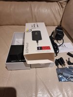
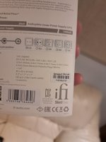
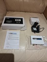
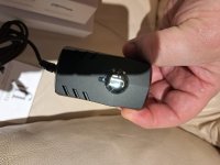
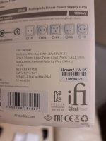
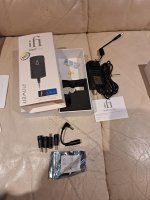
1 Qty. - iFi iPower2 9VDC 2 Amp Power Supply - $65 USD
1 Qty. - iFi iPower2 15VDC 1.2 Amp Power Supply - $65 USD
1 Qty - Swissonic 24/192 A to D Converter - $50 USD


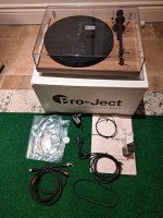
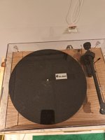
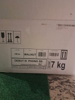
1 Qty - Pro-Ject DEBUT III SB Phono Turntable with Audio Technica AT-VM95SH Cartridge (10 Hours Use)

Turntable Features:

Precision 8.6" Aluminum Tonearm with UPGRADED AT-VM95SH with SHIBATA Stylus (best stylus profile)
High Precision built-in "Speed box" DC speed control for selection of 33 and 45/78 RPM playback
Built-in Moving Magnet (MM) Phono Preamp - BYPASSABLE to your own phono preamp
1.7kg heavy steel platter for best speed accuracy and speed stability
Walnut finished Plinth

Cartridge Features:

Audio Technica VM95 Series cartridge with 2.7 x 0.26 mil SHIBATA stylus
Best Cartridge for the money
Smooth and musical with excellent tracking ability
10 Hours of Use - barely broken-in

A few bonus extras:
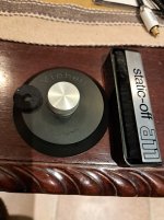
JA Michell Record Clamp with Knurled SS
All Static-Off Carbon Fiber Record Brush Cleaner
Rubber Band to dampen the heavy 1.7kG Steel Platter
Higher Quality Interconnects - better quality than original (included)
Small Circular Level to ensure best tracking

Note: One cartridge tonearm leads re-soldered to connector @ cartridge pins

Will be safely secured in original packaging

$399 USD with FREE Insured Shipping in Canada & USA

Attachments

  • 20250125_182826.jpg
    20250125_182826.jpg
    450.9 KB · Views: 50
  • 1000008026 (1).jpg
    1000008026 (1).jpg
    603.5 KB · Views: 47
  • 1000008021 (1).jpg
    1000008021 (1).jpg
    378.4 KB · Views: 47
  • 1000008024.jpg
    1000008024.jpg
    266.4 KB · Views: 43
  • 1000007999 (2).jpg
    1000007999 (2).jpg
    440.7 KB · Views: 45
  • 1000007996.jpg
    1000007996.jpg
    348.2 KB · Views: 45
  • 1000008022.jpg
    1000008022.jpg
    335.6 KB · Views: 47
  • 1000008023.jpg
    1000008023.jpg
    275.6 KB · Views: 38
  • 1000008012.jpg
    1000008012.jpg
    505.6 KB · Views: 42
  • 1000007998.jpg
    1000007998.jpg
    298.4 KB · Views: 41

How do I refoam a coated cone?

I have several small "woofers" to refoam that have a paper cone coated with a softer, slightly tacky layer. I've peeled away the rotted foam but it leaves a very narrow edge of exposed paper, with a slight 'lip' where the coating starts that I think would interfere with the new adhesive. If I try to expose more paper it tends to want to peel off too much. Abrading the coating only damages the paper beneath.

What's the correct technique?

These are Morel MW-160 units.
NLA and too expensive to replace without first trying to repair them.

20231129_203752.jpg

Kegger/blueglow KT88 PS hum

Hi all, I've build that amp following Mark's excellent video series, and even though I remember Mark saying it was dead quite I have some slight audible 100hz hum out of the speakers (European 50hz mains).
Its about 8mV peak2peak measured at speaker terminals.
The PS for this SE KT88 amp is designed around 380-0-380V, 200mA PT, 5ar4 rectifier and CLC/pi filter for B+ (C1=10uF, L=10H, C2=200uF), and the output transformers are SE 5000k/8R (25:1).
Is my math right that:
1) the first cap should give 100v p2p ripple (assuming full wave rect., 50hz mains and 200mA of current: Vrpp = I/2fC)
2) the LC should smooth the ripple to ~125mV p2p (Vrpp = (Xc/Xl) * Vac(in) with Vac(in) being the p2p ripple V from point 1)
3) the 25:1 OPT should give ~5mV of final ripple at the speaker terminals?

If so, it seems that increasing C1 closer to capacitive max load of 5ar4 (60uF) would be the simplest choice if I wanted less hum. Are there any negative consequences of increasing C1 apart from getting a bit higher current from PT and B+?
With 20uF of C1 I have 79mA and 377V Anode to Cathode at Kt88 so still below 30W and the ripple at speaker terminals halfed as expected...

many thanks

BJT BC548 Transistor characteristic curve question

Hi all,

I am trying to learn small signals amplifying theory and I am having trouble measuring simple characteritics curves for a NPN BJT BC504 transistor.

My setup is as simple as it can be: a single transistor and a standard dual power supply.

Firstly, I give a set current to the base (making sure it is in "ON state) and then I measure the collector current at different Vce voltages.

The problem I am having is that Ibe gets out of wack as soon as I apply Vce... as if Vce is directly linked to Ibe. This dependency problem gets fixed as soon as I place a resistor is series between the supply and the collector and the changes in Vce doesn't alter the Ibe current.

My question is why is this happening but more importantly how are characteristics curves measured if this is happening?

Thanks!

Charles
473055810_1578489802836601_7453420023369009798_n.jpg

Whizzer crossover and phase shift

Greetings to all!

First, please me if this has been discussed here or elsewhere. Could not find anything satisfactory though.

1. Does the mechanical integration of a whizzer have a definite order of crossover? Would it be similar to a 6 dB slope to a tweeter which a single capacitor demonstrates?

2. Does it entail a definite amount/degree of phase shift? Would it be similar to a
what a single capacitor ("1st order" slope) demonstrates?

3. Are there any manufacturer datasheets which disclose phase response of such whizzer based wide band drivers? Or any actual measurements of any such drivers?

It would be greatly helpful if somebody can share something useful on these questions. 🙏

Thanks in advance....
sujat

For Sale NOS 2sa1295 and 2sc3264 pairs

$18 1-9 pairs
$17 for 10 or more pairs
$15 for 20+ pairs

These are genuine parts, I did the following tests to make sure:

Visual inspection of the package
Confirming the bulk Package it came in is what Sanken uses
hfe in range of Batch/grade
Vce breakdown voltage check (these test between 286-302 volts) ie 30% over spec
Most importantly for LAPT's the CE junction capacitance (base actually) is over 300pf for the PNP's and 500pf for NPN's
I broke a couple (in the name of science) to measure the wafer size (its over 5mm) and that it has a dual back plate, fakes usually have a single back plate

I have no doubts these are genuine!

Adjustment of MPA1004 professional amplifier

Good morning,
I was recently given two rack mounted professional amplifiers made by DB technologies, model is MPA1004. They have two channels, 500w each into a 4ohm speaker.
They have inside sixteen mosfets, 8x 2SJ162 and 8x 2SK1058, which are quite rare to find nowadays.
After fixing the pcb, replacing the bad resistors and mosfets, It is time for adjustment, but surprisingly this amplifier has two trimpots for each channel, one for current and one for offset. I never met anything like this before, and I can't find online any info about this and the current needed.
Does anyone have an idea on how these two should be adjusted and where to measure for the calibration?
Regards.
Screenshot 2025-01-07 120525.png

Audio opamp power protection

Hello all,

I play a little electric bass. Electric basses often have onboard preamps or simple buffers which have fascinated me for a while so I am starting to look a bit deeper into them.

My aim at the moment is to create a simple dual buffer, each buffer will "hide" one of the two passive pickups of the bass, before I combine the low impedance outputs to a specialized 25K MN taper pot. There's quite a few reasons I want to keep my passive pickups, but also don't want to directly connect them in parallel, because of all kinds of nasty phenomena I'm reading about and experiencing.

To this end, let's assume we have your average audio op-amp, not examining if it's really suitable for the specific characteristics of the signal coming from the passive pickup while the electric bass is being played. For example let's say we have a TL072 or NE5532 op-amp.

I would like to power the op-amp using two common alkaline (or even lithium) 9V cells. One battery provides the positive rail through its positive connector, the other provides the negative rail through its negative connector. The other connectors are connected, and in fact their junction is the actual ground of the system, our reference for audio. This keeps things nice and simple for starters (as opposed to not having to provide a bias voltage at the center of a single battery power supply). We also get double the battery capacity, double the headroom (although it's much more than is actually needed in this case) plus simplicity - reliability.

What I would like to ask about is a very specific scenario. This would involve one of the batteries not being present, or a battery lead being severed by accident. This would, at least initially, leave either the positive rail or the negative rail at zero volts, with the other one where it should be. Since we are speaking a bit generally, not referring to a very specific op amp, I would like to ask: If the two op-amps suddenly start receiving 0V positive and -9V negative, is it even remotely possible that they will get worn-damaged or completely die? If the possibility is even remotely possible, is there some power protection scheme that can be implemented using simple additional components (like diodes)? One such reaction of a safety circuit would be for example to somehow power the op-amps with +-4.5V from the battery that remains properly connected when the other one's lead is severed. This is just an example, there are probably a lot of best practices on protecting op amps at their power supply pins. Of course, all this may not be much cause for concern in the first place.

I am not thinking about input signal protection as each op-amp's input will be a passive pickup that can not really cause much damage with its output. I plan to place a 1M resistor from the op-amp's input to ground, to set the preferred input impedance and likely stabilize stuff in general.

My understanding of basic electronics, let alone op amps is pretty superficial but I think I can build and test something that will work. Any help with the input power protection aspect of this will be greatly appreciated.

LM4562 / LME49720 EoL? (again...)

Hi,

For the last few weeks, TI's site lists the 4562 and 49720 as out of stock. On top of that, the prices for both have increased by around 80% since I last saw them in stock. They are suggesting the OPA2891 as a replacement (it's a very different OA and my limited experiments suggest that although it's quiet with low source Z, its THD performance is nowhere near the 4562 in most situations).

They made the 4562 / 49720 EOL a few years back, but reintroduced them. Are they gone for good this time? I noticed that they had a few thousand of each just before the price increase... They were snapped up. Maybe someone knew the increase / EOL was coming?

Tube tester calibration/"bogey" tube - info sought - from you realllyyy old guys - like me

Have some Hickok Tube testers to check out.

In the old days, some outfits sold tubes, typically 6L6's that provided a "calibrated"/measured Gm so you could see if (and adjust) at least one particular scale on your testers' meter - if the tester even could read that.

Back sometime in the 90's, Audio Amateur magazine ran an article on how to build a solid state version of it which, as I remember, was basically a hi-power constant current source that you could build into a tube socket and read the Gm.

Actually built a few of them (for different values) when I was into that, but the memory and mags are now long gone. SO, any subscriber that may have currently have the mags and memory be willing to look through them and and maybe post the article.

THANKS

Cabinet lining and rockwool slabs

Hi,
Please could I have a sense check and some advice... I'm planning on building Troels Gravesen TL3 speaker...I've already bought the drivers, crossover components etc....

I've purchased 4mm mass vinyl sheet to line the cabinet walls with, as I've used it before and found it to be benefical. This product...

I had planned on lining the internal walls of the midrange and main cabinet with Rockwool RW5 - 100kg density. See attached sheet that shows the sound absorption coefficient.

I'm having trouble sourcing this material, so was going to purchase a 25mm thick Rockwool acoustic slab product at 200kg/m3 density....

I'm not sure the exact crossover frequency of the bass unit, but I'm guessing it's 1k mark...
My question is, looking at the chart I believe the rockwool would be quite efficient at absorbing a lot of the frequencies below the 1k mark... Would this have the effect of sucking out all of the bass?
If so, I was thinking of maybe boxing in the rear of the horn with the slab product... And just over laying the acousilux product over the sheet vinyl. I omitted the felt from the kit... But could always buy some locally if needed.

Attachments

Paperstone, Anyone?

Hi, All. I'm thinking of building my next pair of floorstanders from a material called Paperstone. It's a countertop material made from compressed recycled paper infused with a proprietary resin. The reasons I'm interested are that it's nearly twice as dense as MDF, it can be worked with carbide woodworking tools, and it would not require additional finishing (paint, etc.). I've previously built veneered MDF cabinets and also solid hardwood cabinets from quartersawn mahogany. I've tested my tools on a Paperstone sample, and my router, table saw, and sliding compound miter saw were successful. I'd use interior Baltic birch bracing set in dados.
Has anyone used Paperstone? The company says that speaker boxes are a "somewhat common application" for Paperstone, so I'm guessing that some commercial builders are using it.

Tu-8500 troubleshooting

I finished assembly of the TU-8500 and here is what I have:
  • LED does not light (tests okay with coin battery)
  • no audio output
  • tubes DO glow
  • I replaced C11, C12, C15 and C16 with Mundorf supreme.

Visually, nothing seems to be wrong with the soldering.
Any ideas about where I should focus?

I have built TU-8200 and Amp Camp Amps (x2) with no issues, so have a little experience.

Attachments

  • IMG_2211.JPG
    IMG_2211.JPG
    640.6 KB · Views: 47

Like New old stock NAD 2700 - works in 4-8ohm setting - stays in protection mode at 8-16 ohm setting

Hi

I recently acquired a NAD 2700 in mint condition on the inside - and have been using it for a few days now - it plays fine and exits protection mode on power on in about 3-4 seconds - what I did discover is that it seems to stay in protection mode when I flip the back ohms setting switch to 8-16 ohms - I am doing this with the speakers disconnected btw - not sure if that makes a difference - anyway I didn’t play around with it too much in the 8-16 ohms- and flipped it back to 4-8 ohm setting as I was a bit weary of it getting stuck permanently in protection mode 🙂 - just wondering why it would be good in one setting vs staying in protection in the other - any quick tests I can check ( voltages etc ) to figure it out if I’m willing to try flipping the switch again? Main caps are original - amp sounds nice once warmed up in the 4 ohm settings - bias measures about 15 mv on one channel and 16 mv on the other - one other thing - this unit looks like brand new on the inside - like it’s been sitting in a closet for last 30 years before being taken out - it’s unreal !

Possible to make a compact PA sub that plays loud and low given a ton of power?

I feel like I know enough about audio to be wrong, but not enough to be right, so thanks in advance for your patience.

I've heard that, if you're willing to sacrifice efficiency, you can more-or-less get as much low extension as you want without resorting to a huge enclosure. Is that accurate? I'm assuming it's incomplete if not outright inaccurate, but I want to understand better.

I'm helping a friend get a live events biz off the ground. Right now we're using a pair of Mackie SR18Ss. They are roughly 2' x 2' x 2' each and give us enough overall output. However, as with most PA subs, nobody's home below 40 Hz without DSP. I'd love it if we could go down below 20 Hz with little or no DSP/EQ, but as I'm sure you all know, there's nothing off-the-shelf in pro audio that plays anywhere near that low unless it's several times the size, and we can't (yet) tote around something that big.

Let's pretend I have access to all the amplification I need. Sky's the limit there. Given that, could I conceivably build a sub not much larger than 2' x 2' x 2' with relatively flat frequency response from like 18-100 Hz without DSP and as much SPL capability as one of our Mackies?

If so, what should I look for in a driver and enclosure design, and what other downsides should I expect it to have (distortion, transient response etc.), if any?

If not, how can I tell how big the enclosure would have to be – again, assuming I can compensate for any lack of efficiency with a boatload of amplification?

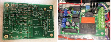
PCB: low voltage On-Off switch drives AC mains relay \ includes soft start .. H9KPXG

I got fed up with DIY power amps whose AC mains On-Off switch is on the rear panel. This choice does reduce the amount of metal working required; just buy an all-in-one plastic molded unit containing IEC inlet jack, fuse holder, and AC mains rated switch. Cut one rectangular hole in the rear panel (where small mistakes in drilling or filing are not visible!), drop in the unit, done! But reaching through the equipment rack to operate a switch on the back panel is clumsy to watch, and awkward to do. I wanted something a little more refined.

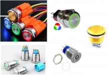
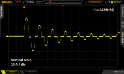
Front panel switches with a circular pushbutton and colored illumination looked promising; the type called "Anti-Vandal" appealed to me. Figure 1 shows a few examples of them. UNFORTUNATELY, most of these switches are rated for low current DC applications like soda vending machines; very few are rated for AC mains switching at the high currents needed by power amplifiers. Worse yet, the inrush current that flows through the On-Off switch at the instant when the gear is turned on, can be enormous. Far too high for a switch rated 2A @ 24VDC. Figure 2 shows the measured AC mains current which flows, when a rather modest chipamp-based power amp (photo) is turned on. The inrush current peak is 24 amperes: (2.4 vertical div X 10 Amps per div). That's quite a stress for everything in the AC mains current path, including the On-Off switch's contacts. And remember, this is not some super-amp behemoth from Krell; it's just an Antek 200VA toroid, two LM3886 amp channel boards, and a diyAudio Universal Power Supply PCB. Yet its inrush current is frighteningly large.

It seemed to me the only way to use the Anti-Vandal On-Off switches I liked, was to use them at low current & low voltage. They wouldn't directly switch the mains; instead they would merely control a separate big, robust, high-current and high-AC-voltage switch. Perhaps such as a mains rated relay or triac.

Regrettably, more than half of these Anti-Vandal switches are momentary pushbuttons; they don't have latch-in-position action like rocker switches or toggle switches. To use them on the front panel of a power amp, an electronic latch or flipflop would be needed, giving "push on, push off" behavior.


SMALL LIGHTWEIGHT FRONT PANEL SWITCHES

Nelson Pass's 1992 amplifier DIY project called A75 (class-A, 75W/ch) used a triac to switch the AC mains off and on. The triac was controlled by a small front panel switch. The circuit reduced switch current to single digit milliamps, but it did require a front panel switch that can withstand the full AC mains voltage (230V in many countries). Very few of the Anti-Vandal switches meet this requirement, unfortunately.

Canadian high-end power amp manufacturer Bryston used an always-on, micropower, low voltage DC supply for their front panel power switch. It fires a triac, and the triac switches the AC mains on and off.

Australian engineer and prolific DIY project creator Rod Elliott offers Project 166 which is a Push-On, Push-Off Mains Switch. It includes an always-on, micropower, 12V DC supply. This powers a logic flipflop circuit which is the memory element for the push-push function. The flipflop operates a 12V relay, whose hefty contacts switch the AC mains on and off.


INRUSH CURRENT LIMITING WITH BYPASS

The measured inrush current waveform in Figure 2 indicates to me that some type of inrush current limiting is certainly needed, no matter how beefy and robust an on-off relay or triac is used. I still want to avoid over-stress of the transformer, the mains fuse, the internal wiring, etc.

I decided to also include a bypass circuit, which completely removes the inrush current limiter a short time after power on, when mains current has settled down to its normal (non-inrush) condition. Both Douglas Self's textbook and also Bob Cordell's textbook recommend inrush bypass circuits, on their page numbers 633 and 459, respectively. Bypassing the ICL reduces its current to zero, so it cools down and becomes ready for the next power-on event (a so-called "hot restart"). Bypassing the ICL also reduces the voltage dropped across it (to zero), which can be significant when the rectifier current-peaks are large. See Cordell p.459 for more.

The basic idea of inrush current limiting with bypass is sketched in Figure 3. Switch "SW1" turns the amplifier On and Off. Series resistor "NTC" performs the function of inrush current limiting. It guarantees that mains current cannot possibly exceed (Vmains / R_NTC) even if the rest of the primary circuit is an ideal short circuit. Switch "K1" bypasses the inrush current limiter after the inrush event has completed and mains current is down to its normal levels.

Inrush limiters have been successfully deployed using (a) ordinary wirewound resistors [Self], and also (b) specialized Inrush Current Limiter components [Cordell]. I decided to use option (b), the special ICL components. They offer a degree of extra safety in case the bypass mechanism fails open-circuit: an ICL can withstand the full primary current indefinitely. Whereas (a) wirewound resistors would self-destruct in less than one minute.

In construction, ICLs are enormous Negative Temperature Coefficient thermistors; a famous example is the CL-60, whose very part number includes CL for Current Limiter. I prefer not to refer to these as thermistors, to avoid confusion with the tiny little temperature sensors that also happen to have a negative temperature coefficient. So I will make an effort to always say "Inrush Current Limiter". Oh by the way, that happens to be the name that both Digikey and Mouser give to the section of their website where these components are sold. Forget Thermistor, remember Inrush Current Limiter.

When should the inrush limiting cease? When should the bypass turn on? Opinions vary. Texas Instruments bypasses the ICL when the amplifier's DC power rails have ramped up to approx. 60% of their final voltage (Fig.5 on p.7). Self suggests bypassing 1 second after power-on (p. 632). Rod Elliott's inrush current limiter for power amps, Project 39, enables the bypass after 0.1 seconds. A brief and incomplete survey of diyAudio discussion threads, turns up recommendations varying between 10 full cycles of the AC mains (0.2 sec) and 100 cycles of the mains (2.0 sec). All of this suggests to me that there are probably more than one right answer, and maybe the shrewd decision is to provide a few user-selectable options. As has previously been done in the Soft As A Feather Pillow soft start design by diyAudio members jhofland and xrk971, I chose the convenient 2X-per-step settings 0.5 sec, 1.0 sec, 2.0 sec. Thus bypass happens either 0.5, 1.0, or 2.0 seconds after power on, selected by a jumper on the PCB.


CIRCUIT SCHEMATIC DIAGRAM

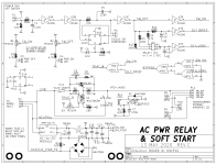
Figure 4 is the schematic of this PCB. The power handling "business end" of the circuit in on the bottom half of the page; the top half is merely timing and LED management.

The actual front panel switch connects at top left; it switches only 5V DC at 0.5 milliamperes. This ripples through some digital logic gates and produces a digital signal "TRIAC_B", which turns on triac T1 through opto isolator U4. When T1 turns on, it applies mains power to the transformer primary windings. Notice that triac T1 is series connected with an Inrush Current Limiter device, "ICL1".

Component ICL1 a 22mm diameter device made by Ametherm, whose surge energy rating is 125 Joules. For 115V applications I recommend part number SL22-20007, whose cold resistance is 20 ohms and whose max continuous current is 7 amps. Thus the inrush current when the ICL is at room temperature, cannot exceed (115 / 20) = 5.8 amps, and that assumes the transformer primary, mains fuse, and AC wiring all add up to 0.00 ohms of additional resistance. [For 230V applications I recommend the SL22-50004, whose cold resistance is 50 ohms and whose max continuous current is 4 amps.]

After a user-selected delay time (chosen by setting a jumper across one of 3 sets of pins on header P7), the inrush current limiting is bypassed. Digital logic signal BYPASS turns on MOSFET Q4, which energizes the relay RL1 and shorts out the (triac + ICL) devices. Now there is no extra resistance inserted; the transformer primary is connected directly to the AC mains.

The relay, the indicator LEDs, and all of the digital logic are powered from a tiny AC-to-DC converter module, U2. Today these are available which meet the sub-0.5W international requirements for standby power, and they are delightfully small and cheap. The big electronics distributors carry modules made by RECOM, Mean Well, CUI, and TDK-Lambda. However the TDK modules are quite expensive (3X!), and the CUI modules are in stock at DigiKey but not Mouser. Since Mean Well appears to have by far the greatest number units in stock and on the shelf at Mouser, that's the one I selected. Eventually I settled upon a 5V model, after realizing (a) 12V relay coils don't consume any less power than 5V relay coils; and (b) LED circuits actually do consume more power when operated from a 12V supply than from 5V. It's only obvious in retrospect. And that's why the board uses CD4000 logic chips -- they work at 12V (and 5V, and 3V, and 18V)

The AC/DC module output is made available at connector P5, in case other circuits within the chassis may need a low voltage housekeeping supply. For example, a "breathing" style LED. I strongly urge you not to connect either of the housekeeping supply terminals (5V_HOT, 5V_COLD) to the ground pin of other circuits. Treat it as its own, self-contained, floating 5V supply. If interfaces are required, use optoisolators between circuits connected to the housekeeping supply, and audio circuits connected to audio ground. That way you cannot pollute audio ground with noise or garbage from the AC-to-DC module. The module is rated for 400mA but I recommend drawing less than 300mA from the P5 connector, to avoid overload.

To soothe my paranoia about electric shock, I've included a 25 ampere bridge rectifier "BR1" between 5V_COLD and chassis protective earth. Now in the very unlikely event that the (class 2!!) AC/DC module develops a short between AC mains LINE and DC output Minus, the mains voltage is shunted straight to protective earth through a very high current pathway: BR1. Even if somebody had connected 5V_COLD to circuit ground, against my recommendations, it still gets clamped to a non-dangerous voltage through BR1.

A couple more details about the circuits connected to the front panel switch. Firstly, a very long debouncing time is conservatively applied (using resistor R2 and capacitor C1), compared to the measured timings of typical switch-bounce events, as reported in The Ganssle Group's debouncing article. After that, a Schmitt trigger (U3A) adds hysteresis. These two mechanisms filter out and remove switch bounces very effectively, and present clean square waves to the downstream logic. Secondly, flipflop U1B is a memory element which remembers the current logical state (am I on, or am I off?) when the front panel switch is a momentary contact device. The PCB user installs a shorting bar across pin header P6 when using a momentary switch on the front panel; this enables U1B. If there is no shorting bar across P6, U1B is disconnected and the non-momentary front panel switch controls On-Off behavior and timing.


STATE TRANSITION DIAGRAM \ TIMING DIAGRAM

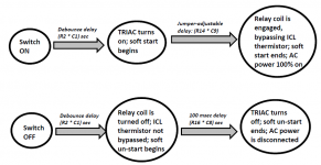
Figure 5 illustrates the sequence of events that occur when the equipment is turned On, and when the equipment is turned Off. As you can see, all delays are set by RC timeconstants on the PCB. Ambitious, self-confident DIY builders can modify these timeconstants, if desired, simply by changing component values.


INRUSH CURRENT: BEFORE AND AFTER INSTALLING SOFT START

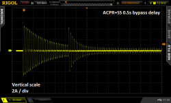
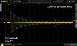
Figure 2 is the "before" measurement; it shows a stereo chip amp's power on event with no soft start applied. Figures 6 and 7 show the same amplifier, but with this PCB installed between the transformer primary and the AC mains.

In both Figure 6 and Figure 7, the inrush current has been reduced quite dramatically. "Before", with no soft start (Figure 2), inrush current peak was 24 amps. "After", with this PCB installed, inrush current peak was only 4.4 amps (2.2 vertical divisions X 2 Amps / div). (The horizontal scale is 100 msec / div as reported at top left in the Figures.)

In Figure 6, a shorting bar has been connected on header P7 from pin 1 to pin 2. This selects the "0.5 second delay" option for ICL bypass. You can see that when the ICL is bypassed, AC mains current jumps up. Because there is suddenly less total resistance in the transformer primary circuit.

In Figure 7, the shorting bar has been moved to pins 3 and 4 of header P7, which selects the "1.0 second delay" option for ICL bypass. Now the bypass comes later, and the up-jump of AC mains current is smaller.

These figures suggest, at least to me, that a setting of 1.0 second delay before bypass is desirable. And that's what I'll be using in my equipment. But other DIYers have the freedom to choose other settings, as they see fit. Thank goodness the jumper select options permit this easily.


CAUTION: I PREFER MY LEDs VERY DIMLY LIT ; YOU MAY NOT

Resistors R3 and R4 set the current flowing in the power-is-on and/or the power-is-off LEDs. I chose quite large resistances for these because I like dimly lit LEDs. You may want to experiment with the LEDs you plan to use, and to discover the resistor values which give the LED brightness that you prefer, with 5V supply voltage. Do this before stuffing and soldering them into the PCB, of course.


(optional tech info): MORE ABOUT INRUSH LIMITER JOULE RATING

The Ametherm ICL I have recommended in the Parts List, is rated for 125 Joules. Is this too little? Too much? Just right? Let's look at a couple typical scenarios.

Example 1: a chipamp with plus/minus 36V supply rails, using a diyAudio Universal Power Supply, whose PCB has a total of eight electrolytic capacitors. Each capacitor is 15,000 microfarads with a 50V voltage rating. Four of these capacitors filter the +36V supply, and four of them filter the -36V supply.

The energy stored in each of the four V+ capacitors, is 0.5 * C * V * V. Plugging in numbers, (0.5 * 1.5E-2 * (+36) * (+36)) = 9.72 Joules. Since there are four V+ capacitors, that's a total of 39 Joules for V+

Similarly the energy stored in each of the four V- capacitors is 9.72 Joules. {why? because (+36) times (+36) equals (-36) times (-36)} The total for V- is also 39 Joules.

Adding them together, the total energy stored in the PSU is 78 Joules. Which is comfortably below the 125J rating of the Ametherm ICL.

Example 2: the AB100 amplifier by Nelson Pass. This is a 100W/ch class AB amplifier with plus/minus 55V supply rails. Each rail has two electrolytic capacitors rated 10,000 microfarads and 63 WVDC. For each capacitor, E = 0.5 * C * V * V = 15.2 Joules. Since there are four capacitors, the total is 61 Joules. Comfortably below the 125J rating of the Ametherm ICL.

Although it's not written in the official published specifications on the seller's website, I have read here on diyAudio that the Intelligent Soft Start board from Neurochrome Audio, allows 250 Joules of inrush current energy (!!). Twice as much as the 125 Joules of this PCB. DIYers who believe they need more than 125 J (but less than 250 J) of inrush current energy, should consider the Neurochrome board to be a good possibility.


SUMMARY OF PCB CHARACTERISTICS \ FEATURES

  • Accepts low voltage, low current on-off switch
  • Accepts either momentary action, or rocker-toggle action, switch
  • Includes inrush current limiting ("soft start") with bypass
  • User selectable delay between power-on and bypass
  • Less than 0.5 watts standby power (when "power is now off" LED is omitted!)
  • Housekeeping 5V DC supply provided
  • 25A safety diodes between housekeeping supply and protective earth
  • PCB mounting holes on 10 mm grid, matching Modushop perforated baseplate: Holes 60 x 90, edges 72 x 102 mm
  • 125 Joules max inrush energy

AVAILABILITY

I have attached the Gerber CAD manufacturing files for this PCB; its unique identifier is H9KPXG . The suffix "-C" indicates revision C of the layout. Anyone can send the .zip archive of these Gerber files to a PCB fab and have boards made; the design is public domain and uncopyrighted. Use them however you wish. I hope if you end up with extra PCBs, you will consider giving them away for free, or selling them at low cost, to other diyAudio members.

I strongly recommend that you have these built using BOTH 2-ounce-copper {double thick} traces, and also ENIG {gold} finish on the pads. An example is shown in Figure 8.

As of today, 23 May 2020, I have about twenty extra boards (2oz, ENIG) which I am willing to sell at my cost: USD 3.50 plus postage. One board per customer. In the present conditions I will be shipping to US addresses only. The required US Customs paperwork and face-to-face handoff for international shipments is, I regret to say, unacceptable to me. If you live outside the US and want a PCB, send these Gerber files to a PCB fab and have them ship boards straight to you. Give away or sell any extras.

A parts list is attached below. If a diyAudio member wants to turn it into a Shared Shopping Cart at Mouser.com, please go ahead with my best wishes. Just remember that 115V builders need one ICL part# while 230V builders need a different ICL part#.

_

Attachments

  • AV_switches_all.jpg
    AV_switches_all.jpg
    278.9 KB · Views: 10,477
  • No_ACPRSS.png
    No_ACPRSS.png
    34.4 KB · Views: 8,814
  • Cordell_softstart_schematic.jpg
    Cordell_softstart_schematic.jpg
    101.3 KB · Views: 9,993
  • schematic_ACPRSS.png
    schematic_ACPRSS.png
    35.5 KB · Views: 10,504
  • diagram_of_SS_timing.png
    diagram_of_SS_timing.png
    66.6 KB · Views: 10,378
  • with_ACPRSS_0p5_sec.png
    with_ACPRSS_0p5_sec.png
    50.4 KB · Views: 4,893
  • with_ACPRSS_1p0_sec.png
    with_ACPRSS_1p0_sec.png
    49.8 KB · Views: 5,367
  • BOTH_BOARD_SHOTS.jpg
    BOTH_BOARD_SHOTS.jpg
    844.7 KB · Views: 5,737
  • Parts_List_ACPR_SS.zip
    Parts_List_ACPR_SS.zip
    8.5 KB · Views: 1,490
  • H9KPXG_AC_mains_relay_SS_revC.zip
    H9KPXG_AC_mains_relay_SS_revC.zip
    95.8 KB · Views: 1,635

"MagicQuartz" DIY turntable speedbox / motor controller

Hello everyone,

I'd like to introduce you to a project that I've been working on since around 2011 - admittedly with longer breaks in between. It is a turntable speedbox (also called motor controller) and is called "MagicQuartz". I had already touched on the project many years ago in another thread here (https://www.diyaudio.com/community/threads/magicquartz-unit.281106/), but I had subsequently paused development due to various other projects. I've been actively working on it again since 2021.

Assembled1.jpg


The project comprises a firmware with extensive documentation and an open-source "blueprint" hardware design, called the "MagicQuartz TechDemo". The firmware is very flexible and runs on the TechDemo or any simply Arduino board. For the latter, you do not even need to have a display -- you can also interact with the firmware over a serial line from a computer. The hardware design comprises a PCB and a 3D-printable enclosure. I think it is very DIY-friendly.

This speedbox is essentially a true sine wave inverter based on a class D audio amplifier and a toroidal transformer to boost the voltage. The speed of the turntable is controlled by changing the AC frequency generated. This enables electronic switching between standard disc speeds (16, 33, 45 and 78 rpm) and real-time speed correction using an optical sensor. Note that this approach only works on turntables with an AC motor. In addition, the firmware support a special automatic voltage reduction, which can significantly reduce motor noise in some turntables (in my opinion, this is even more striking than the speed regulation).

MagicQuartz-Typical-Application-1024x576.png


Some pictures (OpenSCAD renderings) of the MagicQuartz TechDemo:

Rendering-Front.png


Rendering-Back.png


And here are two YouTube videos where I introduce the project in detail:

Login to view embedded media
Hardware-Design: https://github.com/sebmate/MagicQuartz-TechDemo
Firmware: https://www.mate-labs.de/magicquartz/

Final note / disclosure: I originally wanted to commercialize the project. However, due to the (unfortunately!) very low demand and the high level of bureaucracy here in Germany, this is currently on hold. That's why everything is free at the moment.

Would be delighted to hear your feedback!

Sebastian

For Sale Korg Nutube B1 Preamplifier with linear power supply.

Here is a built of the Korg Nutube miniature triode amp. I bought the board and design from DIY audio store and it is based on Nelson Pass design from 2017 Burning amp festival.
It is a 16dB gain preamp, one input and one output for minimalistic system. The output impedance is 140ohms and the input 50k.
It uses a linear power supply, TKD volume pot and Cardas RCAs. Chassis is my Modushop Italy.
For more info read this: chrome-extension://efaidnbmnnnibpcajpcglclefindmkaj/https://www.firstwatt.com/wp-content/uploads/2023/12/art_diy_nutube_preamp.pdf.
Price to sell, asking $200 free shipping to USCON.

Attachments

  • IMG_0585.jpg
    IMG_0585.jpg
    468.8 KB · Views: 125
  • IMG_0586.jpg
    IMG_0586.jpg
    803.5 KB · Views: 127
  • IMG_0584.jpg
    IMG_0584.jpg
    479.2 KB · Views: 128

Filter caps capacitance, should I increase?

Hello,

I am going to ask a question about a subject that I am sure have been covered a few time.

I am recapping a Revox B750. It originally comes with 4x Frako 4700uf 63V. They are roughly 35x55mm.
I have purchased some CDE in the same voltage and capacitance. They are much smaller (30x30, here is the part list https://www.cde.com/resources/catalogs/380-382.pdf )

The old Frako measured at 4400uf after 50 years, the new CDE at 4100uf. Although within the 10% tolerance, I was a bit underwhelmed.

So my question now is, should I buy another set of caps, say 5600uf which I will assume may measure at 5000uf or simply stick with the CDE?
I was thinking of the Kemet ALC70 or ALC80 in 100V that draw much more current and should fit since I have the space ( spec list https://www.mouser.co.uk/datasheet/2/447/KEM_A4081_ALC70-3315930.pdf ). I am sure I could push to 6800uf but I don't want to stress the rectifiers too much.

Most importantly, would I really hear any sonic improvement?

Thank you

Simple Class B or AB Mosfet Amp

Locking for a Simple Class B or AB Mosfet Amp schematic

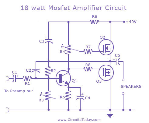
Hi. I am locking for a schematic of a simple class B or AB mosfet amplifier.
I found one which I thought was the ideal, with IRF540/IRF9540, but it does not work.
18-w-mosfet-amplifier-circuit.jpg

Someone knows a schematic of a simple (1~2 transistors + 2 mosfet - preferably IRF) class B or AB mosfet amplifier that works? 20~30W is enought.
The use is for guitar.
Thanks.

Precision Resistor GB? General Resistance (Rhopoint) GG102

EDIT: Looks like we have enough for the minimum order, please commit by Sunday 28 March 2021.

Over on the AD1862 DAC thread there's been some interest in high precision resistors for the I/V section. If there's general interest that yields more than the minimum purchase of $250 I'm willing to put together an order of General Resistance GG102 Squaristors at cost.

Full disclosure: I padded the chip GBs a little to cover fees, have simple worldwide shipping costs and some supply in case things were lost/broken in shipping. The resistors will be all custom, so no backup stock but also lowest possible cost. Unlike the chip GBs, I won't be doing more than one of these.

The resistors are made by General Resistance (actually Prime Technologies) and sold in Europe by Rhopoint, they seem to be better known by that brand.

GG102 Squaristor - Quantity 1-9, 0.1% accuracy, price per resistor

10, 20, 30, 40, 50, 60, 70, 80, 90, 100, 120, 200 $18.41
250, 300, 350, 400, 500, 600, 700, 800, 900, 1.0k, 1.5k $11.13
2.0k, 2.5k, 3.0k, 4.0k, 5.0k, 6.0k, 7.0k, 8.0k, 9.0k, 10.0k $9.29
20k, 25k, 30k, 40k $11.13
50k, 60k, 70k $12.00
80k, 90k, 100k $12.99

5G10 Miniohm - Quantity 1-9, 0.1% accuracy, price per resistor
0, 20, 30, 40, 50, 60, 70, 80, 90, 100, 120, 200 $18.36
250, 300, 350, 400, 500, 600, 700, 800, 900, 1.0k, 1.5k $11.00
2.0k, 2.5k, 3.0k, 4.0k, 5.0k, 6.0k, 7.0k, 8.0k, 9.0k, 10.0k $9.20
20k, 25k, 30k, 40k $11.00
50k, 60k, 70k $11.91
80k $11.52

8G16 Econistor - Quantity 1-9, 0.1% accuracy, price per resistor
10, 20, 30, 40, 50, 60, 70, 80, 90, 100, 120 $9.97
200, 250, 300, 350 $8.67
400, 500, 600, 700, 800, 900, 1.0k, 1.5k, 2.0k, 2.5k,
3.0k, 4.0k, 5.0k, 6.0k, 7.0k, 8.0k, 9.0k, 10.0k $7.16
20k, 25k, 30k, 40k $7.92
50k, 60k, 70k $8.70
80k, 90k, 100k $9.40
180k, 200k $10.97
250k, 300k $12.54
400k, 500k $17.09
1M (12E32) $24.80

0.025% accuracy raises these prices by 25%, 0.01% accuracy raises by 50%

There will be some shipping cost from Prime Technologies, TBD based on order but would be spread across each resistor and doesn't apply to the minimum needed to make the order.

Shipping to you can be in a regular letter envelope by first class mail in the US or rest of world, at your risk without tracking or insurance. Priority mail and other services to add tracking and insurance are possible - starts at $7.95 in the US and $14.50 rest of world (including Canada, sadly).

UPDATED LIST 13 March 2021
Paddy Garcia 2 100R 0.1% 18.41 = $36.82
Vunce ? 1.5k 0.1% 11.43 = ?
Vunce ? 100R 0.1% 18.41 = ?
Luchoch ? 1.5k 0.1% 11.43 = ?
kuka 4 100R 0.1% 18.41 = $73.64
wealas 4 1.5k 0.01% (x1.5) 17.15 = $68.60
geoturbo 4 120R 0.01% (x1.5) 27.62 = $110.48

Finally again more time after decades ...

Dear diyAudio enthusiasts,
that's me:
During my youth and studies at university I had a lot of time (but little money of course) to learn and occupy myself with electronics of all kind. Starting with music electronics and band equipment (even built 2 working guitar tube amps with parth from the trash and selfmade cabinets) I turned my interest to the upcomming computer technology starting with a VIC 20 from Commodore, followed by a self-assebled Apple Europlus (based on an emty board). Unfortunately micro-electronics killed that ambition. However, I once need to repair a MacBook Pro and with all the documenation in the web (of which I would have dreamed of in my early days hahahaha) I achieved. But it was no fun exspecially with eyes getting weaker. During Corona I started to get back to my roots. I engaged in a DUAL HS136 piece (turntable, amplifier) and got it work again. Since then I had a lot of old HiFi pieces on my table, not all I got back to work , but I have a quite divers gear to listen to records, reel tapes, cassettes, cd an FM. And what makes most fun to me: Looking for the fault!
Many frieds and neibors profit from it getting appliances of all kind repaired for only the costs of the replaced parts.
And here is my gear in use list:
Amplifiers/Receivers/Tuners: NAD T-750, NAD 3020, Dual CV1250, Dual CT1450 (Dual CT1240 to be fixed)
Turntables: Dual CST3510, Dual 491A in a CS 1225-1 console (various others not - yet - working)
CD: NAD C 542 , TASCAM Combi CD & Tape CD-A500, enriched by a bluetooth transmitter 🙂
Reel Tapes: Philips N4512, AKAI X201D
Tapedecks: Dual C824, Yamaha KX-360 (a not working :-( NAD 614)

Hope to help & find inspiriation to get my projects fixed

For Sale Yamamoto Soundcraft F-350 horns

I have for sale a pair of rare F-350 horns. They are made from Asada which is Japanese cherry. They have recently been professionally re-finished and look stunning. These are Hypex radial horns with a 2” throat although they also come with 1” adaptors. I also have some 1.5” (sic) adaptors I could let you have. The dimensions are 59w x 33d (excluding adaptors) x 19h cms. It’s getting late here and so tomorrow I will post some photos, some links to some similar current Yamamoto horns and my asking price.

6N6P WCF Help

Hi,

I've started a 6n6p white cathode follower build, wanted it to be a combo buffer/line/headphone stage switching between each. I was basing on Kodabmx's 6n6p wcf headphone stage and a similar headphone stage from moses1202, but omitted the first gain stage as I don't need any gain.

I've made a muchedumbre xl using 6ns7 before, and a couple of Frank's 6sn7 line stage (without regulator) fancied using the OD3 PSU as I had the parts and wanted to try a gas tube.'

I wanted this to be a parts bin job, so used what I have which meant only one choke for the PSU and swapped the second choke for an RC section. I also dropped the 150uf c4 as I read gas tubes will oscillate with more than .1uf on the output. The plan was to see how much current the 6n6p's drew and then tweak the RC dropping resistor and OD3 series resistor and cathode resitor values until I was happy. I've only got a 5w 10k, so was just going to get things working in test then buy a higher wattage, or use some parallel resistors on hand. and also get a small cap < .1uf cap to reduce noise.

The PSU section all works and I get 150v from the OD3 - without the 6n6p load the B+ is about 340v and the OD3 gives 150v. I've wired using the jumper pins so I can remove the OD3 and the B+ is cut, works well.

I've just wired up the buffer input and output to save doing all of the input and headphone cabling, using some .68uf which are fine for my 100k input.

The WCF section is not giving out the voltages I expect. With 150v on the 270 ohm plate resistors I'm only getting 10v at the first triode cathode/second triodes plate, so the 100ohm second triode cathode resistors is seeing mv's where I thought I should see half of b+ so ~75v. I've checked my wiring and compared to my 6ns7 wcf and looks right, but must be a mistake somewhere. The B+ with the 6n6p's loaded is still around 340v.

I wired up without the OD3, so ~380V plate, and got 20v at the cathode/plate output junction and about 4ma through the 6n6p's. I've swapped the grid stoppers between 10k and 300ohm, didn't expect a difference and got none.

I've tried 3 sets of 6n6p and 2 different ez81's. No difference.

I've included the kodabmx and moses1202 schematics, a version with my values and my psu, plus pics of the build. Hoping someone can tell me what I've done wrong 🙂

Once I know what's up I'm going to strip and rewire the WCF section as I should have rotated the 9pin sockets to keep the heater wiring at the back.

ta

Rob

Attachments

  • KODA 6N6P WCF.png
    KODA 6N6P WCF.png
    11.9 KB · Views: 247
  • ECC99 - wcf goes with regulator psu.png
    ECC99 - wcf goes with regulator psu.png
    12.6 KB · Views: 217
  • wcf psu with regulator.png
    wcf psu with regulator.png
    18.6 KB · Views: 181
  • 6n6p wcf psu.jpg
    6n6p wcf psu.jpg
    29.5 KB · Views: 183
  • 6n6p wcf rob.png
    6n6p wcf rob.png
    5.7 KB · Views: 183
  • IMG_8087.jpg
    IMG_8087.jpg
    504.4 KB · Views: 165
  • IMG_8085.jpg
    IMG_8085.jpg
    601 KB · Views: 187

Visual Analyser version 25

From the website https://www.sillanumsoft.org:

” Visual Analyser
is a comprehensive professional real-time software suite that transforms your PC into a full set of measurement instruments, with no additional hardware required (you can use your PC’s sound card). Alternatively, you can use specific external hardware (see the Hardware section for an example). Visual Analyser runs on Windows operating systems. The Visual Analyser 25 Silvia edition is now available (for both 64-bit and 32-bit platforms), though it is no longer compatible with Windows 9x. VA also runs on Linux through the wine utility. Wave, MP3, and FLAC file management were added in the 2012 version and have been further improved in the 25 versions. VA has been adopted as the basic measurement software by Nuova Elettronica magazine (a famous italian magazine that has now ceased all publication).”

“The VA 25 Silvia edition features a new 3D interface, an improved spectrum analyzer, a graphic equalizer, playback and recording tools, a frequency response tool, an updated menu, the ability to capture samples from other applications in real time, and much more.”

I just found this new version today. First impression is that it looks familiar to the previous versions, but with lots of improvements. I will continue with testing.

Regards, Gerrit

TPA3255 in/out power

What's the relation between input and output power of the TPA3255?

https://www.ti.com/product/TPA3255
I'm a beginner...

I don't understand this table Fosi Audio V3 mono:
1737209197006.png


Why can it output so much more with higher voltage?
PSU 32x5=160W and 48x5=240W, so factor 1.5
But at 4Ohm (rated), factor 2.4

I'm using two 36V/6A PS, I thought that might make it heat up less (less stress). Am I wrong?

simple question about tri-amping PA systems

This may be a simple question and may not be the right question to ask, but I am planning a PA system build. I'm going for modest output but wide dispersion in a practically square room. The only components I have currently are 2 Behringer NX6000ds, a Crown XLS 1502, and a Crown XLS 1005.

My question is: Would I be able to build a three-way PA system without passive crossovers by using the low-pass, high-pass, and bandpass filters on these amplifiers?

Behringer NX6000D's running subwoofers
Crown XLS 1502 running mid-range
Crown XLS 1002 running tweeters

Is this how larger PA systems work or am I missing something?

Lowering gain for Hypex ncore modules

This is an advice for all of you using the hypex ncore modules thinking they have to much gain , if you know how to desolder SMD components .

The ncore 122 module has a gain of 25,5 dB .

The ncore module 122 and more, can be modified by desoldering two smd resistors at the buffer stage , lowering the amplifiers gain about 12,5 dB . The opamp buffers now act as unity gain buffers, making the amplifier perfect to drive directly from a dac .

In my case , I use a WiiM ultra as digital preamp using toslink to my rega dac . The rega is directly coupled to my Audiophonics ncore 125 power amp.

Before the gain modification , I could only play music at about 25 ( out of 100 ) on the Ultra volume display.

After desoldering the two resistors , lowering the gain of the amplifier, the digital volume control on the Ultra is often used at 50-60 meaning less digital information is lost and the sound gets slightly better .
IMG_4694.jpeg

Impulse response measurements of Dolby Atmos Soundbar with wireless Subwoofer

I 'm trying to measure the polar frequency response of a Dolby Atmos soundbar with its wireless subwoofer.
I'm using ARTA software with the microphone at 1.5meters. The input signal goes to the AUX input of the soundbar.
The measured Impulse response is delayed around 90 msec which is normal for such kind of speakers that include wireless connection between sound and subwoofer.

The problem is that sometimes the delay is increased up to 1400 msec for reason that I cannot identify.
To solve this problem, the soundbar has to be turned off and turn on again.

Has anyone seen such a problem? Is there something that causes this problem ?

Advice wanted on replacement of a 6" woofer factory installed as a midrange driver in a ported enclosure

I may be over thinking this but....

I have a pair of 3 way speakers from the early 1970's. They are not a common brand - the maker is WEB. I owned them for 15 years or so. I think they are a good sounding speaker and the enclosures are very nicel.

They were out of my possession for about 2 years but recently re-acquired. Unfortunatly the 6" midrange drivers now have damaged voice coils. There is rub and I suspect the voice coils have a break. The tinsel wires are fine.

All of the drivers within the speaker system are CTS - 12" woofer, phenolic ring tweeter . The 6" midrange I am dealing with is acturally catagorized by CTS as a woofer. They publish it's frequency response as 40 to 4,000 and power handling of 10 watts. These 6" drivers are wired in the enclosure as a full range so I can appreciate them as vulnerable to being overdriven which I am pretty sure is what happened to them.

I am considering replacement with some 6" Radio Shack woofers. Specs are not identical but would that matter in a ported enclosure with a 12" woofer and a tweeter? Crossover components are two capacitors - one for the woofer and one for the tweeter.

The Radio Shack woofers I am considering have a frequency response of 50 to 6,000 and power handing of 20 watts

AH! Conical Horns

Hey new member here.

Joined the form to ask if anyone has built any of Acoustic Horn's conical horns? It was a company owned by a person named Bill Woods who passed away I think a few years ago. He made and sold 300hz, 500hz, 700hz, and 1000hz horns. I was wondering if anyone here owned any or if they have built a set of them and can provide guidance. I'm trying to either get my hands on a pair or make them with some plans.

I hope everyone is have a good day.
Stu
Projects by fanatics, for fanatics
Get answers and advice for everyone wanting to learn the art of audio.
Join the Community
507,621
Members
7,880,289
Messages

Filter

Forum Statistics

Threads
405,873
Messages
7,880,289
Members
507,621
Latest member
Octuor