You are using an out of date browser. It may not display this or other websites correctly.
You should upgrade or use an alternative browser.
You should upgrade or use an alternative browser.
Filters
Show only:
Are separate outputs really separate on SMPS?
- By madmarcus
- Tubes / Valves
- 6 Replies
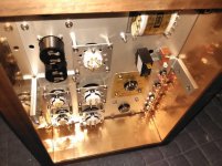
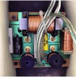
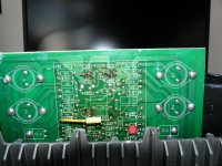
As mentioned in my thread on a workshop bluetooth amp project I have a random SMPS that I am considering for use in an amp. No it's not ideal or normal for a tube amp even if it is marketed as such. But I have it already due to another project that needed 48V with more current (that project is on hold).
Aliexpress SMPS
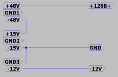
It's configured with three outputs
Output voltage: +48V GNG -48V / current: 2.6A
Output voltage: +15V GNG -15V / current: 1A
Output voltage: DC12V / current: 1A
Given that I can deal with only 1A of current is there anything I should worry about before stacking the +-48V and the +-15V to get a B+ of 126V?
Working with robots hasn't given me much experience with SMPS. The power supply was in my parts drawer but I'd still hate to blow it up with a dumb move based on expecting all three segments to act independently of each other.
Aliexpress SMPS
It's configured with three outputs
Output voltage: +48V GNG -48V / current: 2.6A
Output voltage: +15V GNG -15V / current: 1A
Output voltage: DC12V / current: 1A
Given that I can deal with only 1A of current is there anything I should worry about before stacking the +-48V and the +-15V to get a B+ of 126V?
Working with robots hasn't given me much experience with SMPS. The power supply was in my parts drawer but I'd still hate to blow it up with a dumb move based on expecting all three segments to act independently of each other.
Attachments
High impedance DI advice?
- By 6V6dude
- Instruments and Amps
- 11 Replies
I've got guitar amps with 1M impedance. But I need to split the signal to my mixer so I'm using 1M impedance FET DI box. That makes it 500ohm load on my guitar in total and I can hear the slight top end roll off and loosing some sound is annoying.
Is there anything I can do increase the DI box to at least 3M, perhaps modify it?
Another idea I had was to modify stand alone tube preamp by replacing input 1M resistor with 5M resistor and just run the output from cathode via cap to mixer. I'm just not sure what implications 5M on input would have if any.
I don't know how else I could achieve very high impedance signal splitting so I don't get any signal loss.
Thanks in advance for any advice
Help about High DC Offset
- By lim0nade
- Solid State
- 9 Replies
Hi guys.
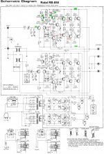
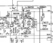
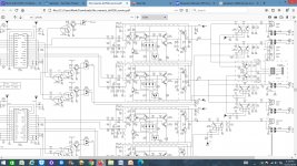
The left channel of my power amp RОТЕL has a high DC offset (13-14V).
I apply a scheme.
In red are the higher voltages measured by me.
Transistors Q 609 and Q 615 have been replaced, but without effect.
Every help will be appreciated!
Greetings!
The left channel of my power amp RОТЕL has a high DC offset (13-14V).
I apply a scheme.
In red are the higher voltages measured by me.
Transistors Q 609 and Q 615 have been replaced, but without effect.
Every help will be appreciated!
Greetings!
Attachments
Welcome fellow diyAudio'ers
- By ukmart
- Introductions
- 5 Replies
Hello there,
My name is Martin and i'm from UK (Essex)
I'm generally into HiFi amplifiers. As I'm fairly new to this topic, I really look forward to learning as much as possible from you guys.
My name is Martin and i'm from UK (Essex)
I'm generally into HiFi amplifiers. As I'm fairly new to this topic, I really look forward to learning as much as possible from you guys.
Soekris dam1202-01 - you pay the shipping
- By bourbon-neat
- Swap Meet
- 4 Replies
Soekris dam0121-01 and Amanero USB input board. Bought in 2015 and never used.
Price = Free
Price = Free
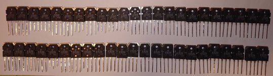
FS: Many OP amps, few transistors
Old stock from inventory clearing of audio electronics company. Everything listed is in new condition and original bought from ELFA Distrelec, directly from the manufacturer, or Digikey throughout the years. Can ship anywhere but if you're outside the EU it might be pricy.
Mostly putting this here in so that someone who is looking for something specific can find it. For some of these components I've got several unopened IC sticks. Some I've only got a handfull left.
OP AMPs:
OPA134PA - Audio
*OPA2134A - Dual Audio
OPA4134A - Quad Audio
LM10CLN - OP AMP & Volt. Ref.
LM324N
TLC2201CP - Low Noise Rail to Rail
MAX477 - Wide BW Unity Gain
EL2044CN - High Speed
EL2444CN - Unity Gain
NE5532D - Dual Low Noise Internally Comp.
NE5532P
UAF771TC
OPA27GU - Prec.
OP284 - Dual
TL061
LM324 - Quad
TS462CN
LM6142BIN - Dual
*AD797 - Very Low Noise Very Low Distortion
TL071CP - JFET Input GP
TL072CN - Dual ^
TLE2062CP - Dual JFET Input High Out. Drive uPower
TLE2064CN - Qual ^
TLE2144ACN - 'Excalibur' Low Noise Prec.
LM6144BIN - Quad High Speed Rail to Rail
LT1028 - Ultra Low Noise
LM837N - Quad Low Noise
LMC6084IN - Prec. CMOS Amp.
LMV934 - BJT Pair
CA741CE
Other stuff:
2SJ115 and 2SK405 Pairs - Audio Transistor
CA3080E - Transconductance AMP.
STP60NE06 - NMOS
V23092-A1012-A301 - Relays 12V, 400V SW.
MTD20N03HDL - NMOS
I've got a lot more that I didn't list here, if you're looking for something specific throw me a message.
Edit: List items in *italics are no longer available.
great capacitor video
- By ga77a
- The Lounge
- 25 Replies
Which Capacitor Do I Use? Tech Tips Tuesday - YouTube
hi diyaudio lad's
while on my journey of trying to understand audio circuits i came across this guy a couple of months ago. today i watched this video and was so impressed by it that i had to share. i'm sure that some of you would have already seen it, so this is really for other novice's like my self. enjoy 🙂
gaz
Measuring speakers T/S values - DATS v.3.0 vs factory specs
- By portakalx2
- Multi-Way
- 38 Replies
Hi, I've seen a similar thread where someone asked whether to rely on DATS measurements or the factory specs. I bought a SEAS coaxial driver and measured it with DATS v3.0. I was very careful in testing/calibration etc and broke the drivers in for several hours at 30Hz beforehand. The T/S values came out very different than the specs and I know that this happens a lot. When I simmed it, the box size and the f3 were different as well. So I contacted SEAS and asked them for guidance. The SEAS engineer assured me that their measurements are correct and insisted that I should use their measurements. So I made the boxes using the factory data. Somewhere else in the forum, I read that the DATS "guesses" the Qms, Qes and Qts values based on the impedance graph. So now I'm wondering how reliable measuring is. How can I make sure I'm using the right T/S values in my sims?

Information Overload
- Multi-Way
- 5 Replies
Maybe some of you fine folks could help lead me in the right direction. I need help choosing the right DIY build.
I'm looking for plans. I don't need a flat pack or anything. I can take care of the woodworking.
I have a budget of around $600.
I have a large, open room that's not the best, it's a bit reverb-y.
I'm using a Marantz HT receiver.
Although this is the beginning of my audiophile journey, I've been a professional musician/music lover my entire life and spent a lot of time in studios/stages.
I used to build SQ car audio systems.
I'd really like a floorstander, if possible.
My #1 main concern is fidelity, accuracy, detail, soundstage, clarity, etc.
I will be running a subwoofer so it doesn't matter about subterranean bass.
Help expert designers with xover
- By magnethead
- Multi-Way
- 4 Replies
Good morning! Hope everyone had a wonderful and joyous Christmas considering the circumstances. I am starting a new ported 2way, drivers will be a Dayton Dc200-8 woofer----29hz to 3,000hz and a Dayton Dc28 F tweeter 1,300 to 20,000 in a 1.2 cu ft box and a 2inX 6.5in long port. The big question is where would you cross these two drivers? And what order xover would you use. Any advice would be greatly appreciated. Thanks!
LX mini analog crossover
- By Dennis Hui
- The diyAudio Store
- 13 Replies
Hi Jason,
I wonder if you there's an ETA on the availability of the lx-mini crossover?
Thanks,
Dennis
I wonder if you there's an ETA on the availability of the lx-mini crossover?
Thanks,
Dennis
Francesco Campedelli T-Line
- By DIYampNOOB
- Full Range
- 63 Replies
I got bored one night and made a Google Sketchup model of Francesco Campedelli's TiLine for HIVI's B3S and BSN. I myself will be using the Aurasound NS3-193-4A. Hope this helps someone!
Attachments
300B SE as my first tube amp
- By tamra
- Tubes / Valves
- 42 Replies
Hi all.
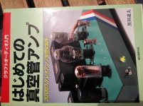
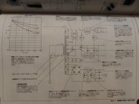
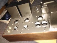
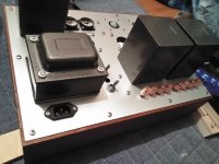
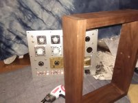
I would like to share building 300B se amp from a book.
Posting might push my self...
Its my first experience and I had no knowledge/understanding tubes, cirkit etc.
Reading book, gathering items took me 6 month now.
I put copper tape for shield(May be it works?)
I would like to share building 300B se amp from a book.
Posting might push my self...
Its my first experience and I had no knowledge/understanding tubes, cirkit etc.
Reading book, gathering items took me 6 month now.
I put copper tape for shield(May be it works?)
Attachments
-
 P_20181030_184416.jpg546.3 KB · Views: 1,248
 -
 P_20181030_183541.jpg438.1 KB · Views: 1,237
 -
 P_20181030_184044.jpg558 KB · Views: 1,246
 -
 P_20181106_202710 (1).jpg465.8 KB · Views: 1,174
 -
 P_20181106_202727 (1).jpg709.3 KB · Views: 1,131
 -
 P_20181106_195359 (1).jpg508.2 KB · Views: 508
 -
 P_20181106_201828 (1).jpg651.5 KB · Views: 537
 -
 P_20181106_202909.jpg527.2 KB · Views: 626
Amp Section: What kind of film capacitor is used between voltage power supplies?
- By gghodg
- Solid State
- 9 Replies
Hi All,
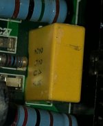
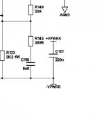
I'm trying to figure out what kind of film capacitor is pictured here (C121). I know its
220nF rated at 275 VAC. I'm limited to sizes 13mmx5mm or 13x6mm which narrows down my options on mouser to general purpose or power factor correction capacitors. I know I can find more information like used for EMI suppression by digging deeper in the data sheets. I don't know what their purpose is though, and they don't show the X2 rating. Are these capacitors "across-the-line"? Any help would be appreciated. Thanks and good day / evening.
Attachments
(Quantity = 4) populated Bob Cordell Super gainclone LM3886 boards
info: https://www.diyaudio.com/forums/chi...-pcb-lm3886-stripped-version-compact3886.html
saves you a ton of money and time on ordering parts:


includes new LM3886 chips that i bought from mouser
all parts are exactly as the BOM and all parts are highest quality and no used parts. all new.
price $199 plus $10 to $15 for shipping depending on destination
saves you a ton of money and time on ordering parts:
includes new LM3886 chips that i bought from mouser
all parts are exactly as the BOM and all parts are highest quality and no used parts. all new.
price $199 plus $10 to $15 for shipping depending on destination
nuvistor MC step up
- By reinhard
- Tubes / Valves
- 88 Replies
Hello tubies,
can anyone help with information on nuvistor MC step up amplifier. As I know Conrad Johnson has made such things in the past. What about noise? Is the nuvistor a good part for that application?
Reinhard
can anyone help with information on nuvistor MC step up amplifier. As I know Conrad Johnson has made such things in the past. What about noise? Is the nuvistor a good part for that application?
Reinhard
Replacing MR752 for MUR860 diodes
- By legarem
- Solid State
- 3 Replies
Hello
I plan to replace power supply diodes in a Linn LK280 amp
They use MR752 diodes 6 A (Ta) 22 A (TL), 400A (IFSM) I was planning to use MUR860 rated 8A (Iav), 100A (IFSM)
Should I only compare MR752 6A to MUR860 8A specs ?
Is it finally safe to replace the MR752 to MUR860?
Thanks
I plan to replace power supply diodes in a Linn LK280 amp
They use MR752 diodes 6 A (Ta) 22 A (TL), 400A (IFSM) I was planning to use MUR860 rated 8A (Iav), 100A (IFSM)
Should I only compare MR752 6A to MUR860 8A specs ?
Is it finally safe to replace the MR752 to MUR860?
Thanks
CNC plans for planet10 designs
- By itsikhefez
- Planet 10 hifi
- 1 Replies
Is it possible to buy the CNC plans that were used to cut the various flat-paks that were sold over the years?
Such as FH3's, types of onkens and baby wodens?
I have someone local that can CNC cut wood, so having those plans on hand is very useful.
Thanks
Such as FH3's, types of onkens and baby wodens?
I have someone local that can CNC cut wood, so having those plans on hand is very useful.
Thanks
Newbie questions re phono pre build (esp PH16)
- By Rossputin
- Analogue Source
- 9 Replies
Hello all,
I'm hoping to get some good advice from you experts as I embark on building a tube phono pre. Thinking about PH16. A couple of basic questions:
Is it a good idea to put the power supply in a separate box/chassis?
What's the best way to get PH16 (or similar) to work with 0.4mV MC cartridge?
What's the best way to cut my own holes in a blank chassis, and any specific recommendation for rectangular holes?
Would you typically go with the parts kit (separate from the tubes) that are available for purchase with the PCBs or buy your own parts?
Are there important factors other than "it looks cool" vs "more issues with dust" in whether to have the tubes coming up out of the top of the chassis?
Thanks very much for any advice!
Ross in Colorado
ES9018K2M vs PCM5102A "other things equal"
- By dandreye
- Digital Line Level
- 7 Replies
Hi All,
Apologies for the offtopic as there's no DIY involved... which of these 2 can be expected to give better SQ via RCA output: Version A (PCM5102A) or Version B (ES9018K2M)?
Lossless HIFI CSR8675 APTX HD Bluetooth 5.0 Wireless Receiver Adapter ES9018K2M PCM5102A I2S DAC Decoding 24BIT TWS 3.5M RCA|Digital-to-Analog Converter| - AliExpress
The former one is GBP5 (~17%) cheaper elsewhere (it's no longer available at the advert above).
Many thanks in anticipation!
Tweeter attenuation help
Hi my first post so please be kind 😱
First a bit of background about me: I've built my own speakers in the past, but nothing advanced or complex. I essentially bought an off the shelf cross over and carefully chose tweeters and mid bass (all SEAS units) of the same stated SPL levels. Wired them all up and put them in a box that i built (having used the t/s parameters of the mid bass to design the box). So I've never done anything complex with crossovers hence my question here.
I have a pair of second hand Monitor Audio GR20 speakers, which are at least 15 years old I believe. These:

This is the measured (from here SoundStage! Measurements - Monitor Audio Gold Reference 10 Loudspeakers (10/2001)) listenting window frequency response of the GR10 which uses the same mid and tweeter (though obviously will have more bass weight and extension):
I've never been quite happy with the treble performance. Difficult to describe but overall it was qualitatively uneven (cymbals and guitars just didn't sound quite right). Oddly even though the graph above doesn't seem to show it the top end was just too loud overall (i ended up using the speaker grills which helped but led to other compromises), though of course that may be due to the room.
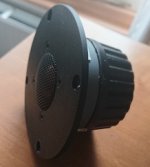
So having done a bit of reasearch and finding that MA use modified SEAS tweeters (attached is a picture of the old units) i decided to take a bit of a risk and get some replacement tweeters from SEAS. (having used SEAS units in the past I felt i at least knew they wouldn't be bad units). The units I chose are the 27TBFC/G. As i had no idea what the SPL of the existing units were I was expecting to have to pad them down as I thought it was unlikely that the exiting units had a higher sensitivity. But I decided just to swap them out first and see what i was left with. I was surprised that my first reaction was "they sound dull". As it happens it would seem like (purely from listening) that actualy the overal vocal range and mids are just much better balanced and the new tweeters are actually overall better integrated (again purely from listening) than the old ones.
Anyway to finally get to why I'm here (sorry for the long preamble). After a few days adjusting to the new balance I feel like the new tweeters could do with a tiny bit of a drop. The lower treble (going to guess the 3-5k region) feels just a touch too hot, (clearly i was expecting this region to be hotter as i expected the new tweeters to fill out the the suckout the old tweeters had, but it's gone just a touch too far). So i'd like to try padding down the tweeters by just 1db to see how they sound. I've measured the DC resistance of the old and new tweeters at 5.3 ohms, (about .5 ohm higher than SEAS state for the new tweeters, and presumably the old, but i'm going to put that down to my mulitmeters accuracy - it seems very sensitive to how the probes are positioned). According to MA the cross over is 2.7khz.
Attached is a picture of the exitsing crossover that i've managed to find. Going purely by a thread on this forum about the GS20 crossover, (here: Please help for Monitor Audio GS20 crossover tuning), I'm guessing the current one is a 2nd order HF (with a 3.3 Ohm resistor in series before the filter ciruit), first order mid (with notch filter) and first order bass.
So finally to my question 😱: As i don't want to mess around with cutting and soldering any of the existing wiring (and defintely not going to pull the speaker apart to start changing the original cross over) I was thinking of trying just a shunt resistor in parallel with the new tweeter to pad it down.
a) would this work?
b) what value resistor will i need to use to achieve a 1db drop? (according to the SEAS specs impedance runs 5 to 7 ohms between 2khz and 20khz on the new tweeters). I'd like to minimise any top octave drop in level/shelving of the response as much as possible. I'm thinking somewhere between 30 and 40 ohms?
Anyway goal is to drop the overall tweeter level by just 1db at this time, preferably using just a parrallel resistor, which I could solder on the existing wiring tags (thus avoiding having to put a soldering iron anywhere near the new tweeters).
I have no means to measure the speakers, and in all honesty I don't really want to get caught up in the effort all of that would entail. The speakers sound much better than they did previously, I'd just like to bring down the overall level of the tweeters a touch as i think they'd sound a bit better still if i did.
First a bit of background about me: I've built my own speakers in the past, but nothing advanced or complex. I essentially bought an off the shelf cross over and carefully chose tweeters and mid bass (all SEAS units) of the same stated SPL levels. Wired them all up and put them in a box that i built (having used the t/s parameters of the mid bass to design the box). So I've never done anything complex with crossovers hence my question here.
I have a pair of second hand Monitor Audio GR20 speakers, which are at least 15 years old I believe. These:
This is the measured (from here SoundStage! Measurements - Monitor Audio Gold Reference 10 Loudspeakers (10/2001)) listenting window frequency response of the GR10 which uses the same mid and tweeter (though obviously will have more bass weight and extension):
I've never been quite happy with the treble performance. Difficult to describe but overall it was qualitatively uneven (cymbals and guitars just didn't sound quite right). Oddly even though the graph above doesn't seem to show it the top end was just too loud overall (i ended up using the speaker grills which helped but led to other compromises), though of course that may be due to the room.
So having done a bit of reasearch and finding that MA use modified SEAS tweeters (attached is a picture of the old units) i decided to take a bit of a risk and get some replacement tweeters from SEAS. (having used SEAS units in the past I felt i at least knew they wouldn't be bad units). The units I chose are the 27TBFC/G. As i had no idea what the SPL of the existing units were I was expecting to have to pad them down as I thought it was unlikely that the exiting units had a higher sensitivity. But I decided just to swap them out first and see what i was left with. I was surprised that my first reaction was "they sound dull". As it happens it would seem like (purely from listening) that actualy the overal vocal range and mids are just much better balanced and the new tweeters are actually overall better integrated (again purely from listening) than the old ones.
Anyway to finally get to why I'm here (sorry for the long preamble). After a few days adjusting to the new balance I feel like the new tweeters could do with a tiny bit of a drop. The lower treble (going to guess the 3-5k region) feels just a touch too hot, (clearly i was expecting this region to be hotter as i expected the new tweeters to fill out the the suckout the old tweeters had, but it's gone just a touch too far). So i'd like to try padding down the tweeters by just 1db to see how they sound. I've measured the DC resistance of the old and new tweeters at 5.3 ohms, (about .5 ohm higher than SEAS state for the new tweeters, and presumably the old, but i'm going to put that down to my mulitmeters accuracy - it seems very sensitive to how the probes are positioned). According to MA the cross over is 2.7khz.
Attached is a picture of the exitsing crossover that i've managed to find. Going purely by a thread on this forum about the GS20 crossover, (here: Please help for Monitor Audio GS20 crossover tuning), I'm guessing the current one is a 2nd order HF (with a 3.3 Ohm resistor in series before the filter ciruit), first order mid (with notch filter) and first order bass.
So finally to my question 😱: As i don't want to mess around with cutting and soldering any of the existing wiring (and defintely not going to pull the speaker apart to start changing the original cross over) I was thinking of trying just a shunt resistor in parallel with the new tweeter to pad it down.
a) would this work?
b) what value resistor will i need to use to achieve a 1db drop? (according to the SEAS specs impedance runs 5 to 7 ohms between 2khz and 20khz on the new tweeters). I'd like to minimise any top octave drop in level/shelving of the response as much as possible. I'm thinking somewhere between 30 and 40 ohms?
Anyway goal is to drop the overall tweeter level by just 1db at this time, preferably using just a parrallel resistor, which I could solder on the existing wiring tags (thus avoiding having to put a soldering iron anywhere near the new tweeters).
I have no means to measure the speakers, and in all honesty I don't really want to get caught up in the effort all of that would entail. The speakers sound much better than they did previously, I'd just like to bring down the overall level of the tweeters a touch as i think they'd sound a bit better still if i did.
Attachments
Nagaoka MP11 Boron
- Analogue Source
- 14 Replies
Hi all. I have a question re. a possible design change to a vintage stylus I have and am hoping someone can shed some light on it.
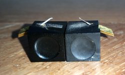
With reference to the attached photograph:
I have a Nagaoka MP11 boron cartridge that I have had since about 1983 and a few weeks ago I decided I would like to start listening to it once again, but long story short, in the process of swapping headshells I dropped it and damaged the stylus.
Anyhow the desire to hear it play once again did not abate and I managed to track down a second-hand example and bought it. On comparing the styli I find that they are significantly different. My original one, on the left is a plain tubular design, flattened off at the tip, whereas the replacement example has a shaft mounted into a collar near the base and has no flattening of at the tip at all.
These seem to be very different designs and I find it strange to find that they are both designated the same model number - MP11 Boron. Surely such different approaches to presentation of the tip must result in significant differences in performance?
Can anyone explain what I am seeing here, or shed any light onto the history of this cartridge/stylus?
Thank you and regards.
Attachments
LTC spice clean up
- By steveu
- Software Tools
- 0 Replies
If you use LTC spice, you probably have a bunch of large temporary files that hang around using up disk space. I have found it very useful to place a file delete utility in the windows sendto folder. The Windows sendto folder has moved around with different windows versions but the current location is something like
%userprofile%\AppData\Roaming\Microsoft\Windows\SendTo
The file itself is a very simple bat file "spice cleaner.bat":
%~d1
cd %1
del /S *.raw *.log *.fft
pause
You just right click a folder, sendto -> "spice cleaner.bat". I prefer to pause the script before it closes so that I can see what has been found and deleted.
cheers,
Steve
Wanted Sony BX269A IC / TA-8650
Hello I am looking for the above IC, it is from the tone control stage in my TA-8650 Amplifier.
Thanks
Gary
Thanks
Gary
DSP Decisions
- Car Audio
- 5 Replies
I've been building my system for the past year or so. Here's my setup so far
Front: Focal ES165 K2 & Matching tweeters biamped
Rear: Hertz Hi Energy 165 component set
Subs: JL 12W3 shallow subs
Amps: JL 1000/1 (class D) and two Mosconi amps for the front/rear speakers
DSP: DBX Driverack PA2 modified to run on 12v
Sound deadoning 80% complete. Required removal of seats and carpet
The Focals take up four of the six channels of the driverack since they are biamped. This has a huge advantage since the tweeters a bit overpowering at high volumes. The DSP's limiter takes care of this. The other two channels are used as a limiter for the subs. This is essential as it's difficult or impossible to hear when they're reaching their limit.
With the recent addition of Hertz in the rear, I'll need a couple more channels of processing. Here are my thoughts so far:
- Put a compressor on the subs to free up a couple of channels on the driverack
- Use a SigmaStudio compatible DSP chip
- MiniDSP C-DSP 8x12
- Add another driverack
Sprint Layout 5.0 Double side pcb question
- By mot on/off
- Software Tools
- 6 Replies
Hi everybody!
Merry Christmas 🙂
Till now i'm using Sprint Layout 5.0 for one sided pcbs fine.
I'm in the procedure of designing a double sided pcb for a DAC and i'm realy confused.
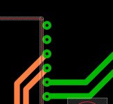
I put lets say a DIL28 (CS8412) in C2 side and now i need to add a track in C1 side connected to a pin of IC.
How i can add the pin pads in C1 side too? Only manualy?
Thank you very much.
I added 3 photos.
Merry Christmas 🙂
Till now i'm using Sprint Layout 5.0 for one sided pcbs fine.
I'm in the procedure of designing a double sided pcb for a DAC and i'm realy confused.
I put lets say a DIL28 (CS8412) in C2 side and now i need to add a track in C1 side connected to a pin of IC.
How i can add the pin pads in C1 side too? Only manualy?
Thank you very much.
I added 3 photos.
Attachments

Thermalright Heatsinks and fans
I'm listing these in hope that someone has a use for them for some kind of DIY project.
Enermax T.B. Silence 120mm Ultra Quiet Twister Bearing Cooling Fan (quantity 2)
link: https://www.amazon.com/Enermax-Silence-Twister-Bearing-UCTB12/dp/B003IB2HYA
price each: $9.99

Thermalright Ultra 120 eXtreme CPU cooler
Link: Ultra-120 eXtreme Rev.C – Thermalright
price: $29.99


Thermalright IFX-14
link: IFX-14 – Thermalright
price: $29.99


intel 115x and AMD AM4 mounting hardware for thermalright Ultra eXtreme 120 and IFX-14 (quantity 1)
https://www.amazon.com/Thermalright-100700553-Optional-Mounting-Installation/dp/B00UN05Q6A
as a bundle together $90 shipped and paypal'd
Enermax T.B. Silence 120mm Ultra Quiet Twister Bearing Cooling Fan (quantity 2)
link: https://www.amazon.com/Enermax-Silence-Twister-Bearing-UCTB12/dp/B003IB2HYA
price each: $9.99
Thermalright Ultra 120 eXtreme CPU cooler
Link: Ultra-120 eXtreme Rev.C – Thermalright
price: $29.99
Thermalright IFX-14
link: IFX-14 – Thermalright
price: $29.99
intel 115x and AMD AM4 mounting hardware for thermalright Ultra eXtreme 120 and IFX-14 (quantity 1)
https://www.amazon.com/Thermalright-100700553-Optional-Mounting-Installation/dp/B00UN05Q6A
as a bundle together $90 shipped and paypal'd
Selection guidance for LEDs
- By wgh52
- Solid State
- 12 Replies
Hello Folks!
My LED application is supposed to signal OK with a green (3mm) LED and "not OK" with a red LED. The two LEDs are in different parts of the circuit and don't have common ground or supply.
I'm looking for a green and a red LED each providing the about same subjective brightness, but don't know which brightness (in mcd) to choose.
I'm also somehow missing a diagram in LED datasheets telling me the typical brightness vs. Diode current or/and voltage which would also be helpful in judging circuit sensitivity.
Any help enabling me to choose or proposal of specific LEDs for the purpose is thankfully appreciated!
Greetings,
Winfried
Quad 909 question
- By Roksan
- Solid State
- 7 Replies
Hi I just wondered if anybody knows whether the 0.1uf cap (yellow) which connects from D14 to R16 (as per pic) is a valid quad modification or not. I would also be interested if anybody has any idea's on the purpose of this capacitor. I purchased the amp many years ago secondhand (unmodified at the time) however the capacitor was present at the time of purchase.
t
t
Attachments
3-way hifi speakers: diy or not?
Hi,
I finally have time and funds to start completing my
HiFi, and speakers are first part I want to get done.
I have a budget of about 2000 euro for speakers. While I do realize this isn't much in HiFi world, I hope I can get a decent result at this budget.
My listening room is 4.5x5m, I mostly listen jazz, soul, and pop music.
So I'm thinking about 3 way speakers (floorstander or big stand on).
I have average woodworking skills, some experience in diy electronics and a very good equipped workshop, but my experience in speaker designing is poor.
So I'm asking you, is diy a good idea for me or shoud I go with some commercial solution?
Ps, I was thinking about some of the Gravesen projects, they seem to be very detailed and with little-to-none tweaking required.
Thanks
Advice on what to match with a 15" woofer
- Multi-Way
- 2 Replies
Hi all,
I found in the basement a RCF L17/64AF (15 inch) speaker, and it triggered me to try & build my own speaker set. As I'm an absolute beginner and I'm here to get some advice.
- What other speakers should I match with the RCF I already have? (tweeters etc)
- Should I try to get another RCF box to have everything in twofold, or can I look for a similar woofer as the RCF for the matching box? If so, any advice on which one?
- I'm a guitarist. Should I better make a guitar amp out of the RCF I have?
Sorry for this absolute beginner questions. I really want to learn!
All best and many thanks,
Simon trinidad
I found in the basement a RCF L17/64AF (15 inch) speaker, and it triggered me to try & build my own speaker set. As I'm an absolute beginner and I'm here to get some advice.
- What other speakers should I match with the RCF I already have? (tweeters etc)
- Should I try to get another RCF box to have everything in twofold, or can I look for a similar woofer as the RCF for the matching box? If so, any advice on which one?
- I'm a guitarist. Should I better make a guitar amp out of the RCF I have?
Sorry for this absolute beginner questions.
I really want to learn! All best and many thanks,
Simon trinidad
Identifying drive units
I have a pair of Monitor Audio GR20 speakers and I was wondering if anybody could identify the mid/bass unit (I've seen mentioned elsewhere that MA often use modified SEAS units):
Mid Bass:


It doesn't look like any SEAS unit i can find on their website. To start wtih I can't find any SEAS aluminium coned driver that has that inverted surround. But there are older units on the site that don't ave actual pictures. This one for example:
http://www.seas.no/images/stories/vintage/pdfdataheet/h1008_l17rep.pdf
Barring anyone here knowing anything about this mid bass unit, what would be the best way of finding out it's frequency response and impedance curves? (not worried about it's t/s paramaters as obviously it's already in a cabinet designed for it by MA).
I've asked MA for advice on replacing the tweeters in the past, but go no response to two emails. So i don't hold any hope that they'll give me the tech specs on one of their drivers. Must admit I was very surprised by their lack of response, as I was half asking them if there were any units they could sell me that would be better than the originals.
Mid Bass:
It doesn't look like any SEAS unit i can find on their website. To start wtih I can't find any SEAS aluminium coned driver that has that inverted surround. But there are older units on the site that don't ave actual pictures. This one for example:
http://www.seas.no/images/stories/vintage/pdfdataheet/h1008_l17rep.pdf
Barring anyone here knowing anything about this mid bass unit, what would be the best way of finding out it's frequency response and impedance curves? (not worried about it's t/s paramaters as obviously it's already in a cabinet designed for it by MA).
I've asked MA for advice on replacing the tweeters in the past, but go no response to two emails. So i don't hold any hope that they'll give me the tech specs on one of their drivers. Must admit I was very surprised by their lack of response, as I was half asking them if there were any units they could sell me that would be better than the originals.
input for ACA?
Hi,
I want to build my first solid state audio amp, and I've decided to build an ACA. I have built vintage clone guitar tube amps, a few active speakers, repaired vintage integrated amps, turntables, and speakers, and built various small solid state projects, so I'm not anticipating difficulty. I'll be using a linear power supply (AnTek toroidal Xformer, etc), it will not be monoblocks, just one stereo amp.
My quandry is that I don't know how to deal with the input. Do I have to use a preamp? If so a passive one or an active one or just a buffer? I've never owned separates before, just integrated amps all my life, and I'm ignorant about this. I thought "line level" was a standard thing but apparently it varies from one source to another. Of courses the ACA doesn't have input sensitivity control.
The music sources that I imagine using are
1) a turntable
2) a CD player
3) a Raspberry Pi music server with a DAC hat.
Any advice or knowledge on this would be greatly appreciated.
Thanks,
Rob
Quad 44 Preamp - Is it worth keeping and upgrading
- By eldarvanyar
- Solid State
- 15 Replies
Hi,
I have a Quad 44 which I bought a couple of years ago. It's all standard and a mark II version according to the Dada Electronics website.


I have been doing some reading regarding the Quad 44 and I am unsure about the real potential of this preamp and whether I should invest some money in it before using it, or just sell it and put the money into something else.
I am also thinking about having a passive preamp made by BTE Designs as well, so have to decide on which to do first.
Either amp would feed into a Quad 606 MK1 power amp, which I bought earlier this year and immediately sent to Quad for a service, and they also upgraded the PSU to 909 spec.
I am aware that there is the DIY route with DADA Electronics
Quad 44 MKII DIY Upgrade and Revision kit Deluxe
Quad 44 MKII DIY Upgrade and Revision kit Deluxe
I would have to get someone to do the soldering and upgrading for me due to being post stroke and my eyesight not being very good close up
Redhill Audio
QUAD 44 PREAMP UPGRADE - STAGE 1
Elna Cerafine audio-grade electrolytic capacitors
Additional, high-quality Panasonic PPS film capacitor decoupling added to remove noise from critical areas
Solid Film MKS signal path capacitors
Unnecessary signal path capacitors bypassed for reduced grain and a cleaner sound
A well chosen blend ofLME49710NA/LM4562NA National Semi & Texas Instruments Op amps for better refinement and improved detail
Quad 44 Preamp Upgrade - Stage 1
QUAD 44 PREAMP UPGRADE - STAGE 2
Increased capacity Low-ESR Power Supply Capacitors
Output signal path capacitors upgraded to solid film types
Elna Cerafine Decoupling capacitors
LME49710 & TI/National Semi Opamps
Panasonic PPS Bypass Capacitors
2 x Red Hill Audio Mini-Shunt Voltage Regulators +/-15v
Signal Path Improved with Audio Wire "Silver Signal"
http://redhillaudio.co.uk/hifi-upgr...reamp-upgrades/quad-44-preamp-upgrade-stage-2
Amplabs who do upgrades as well.
http://www.amp-labs.co.uk/q44fs-a.htm
Rob from Amplabs serviced and upgraded a Quad 303 that I bought a couple of years ago
http://www.amp-labs.co.uk/servicing.htm
He originally serviced a Yamaha CR1000 for me which I stupidly sold a couple of years ago but he only works on Quad now I think.
I have read online that the Quad 44 suffers from the 4066 CMOS Chip which was originally designed for and used in the Plessey System X Telephone exchanges, and is naturally bandwidth limited.
Other issues include the use of the Op-Amp TL071 as was used in the 405 power amp.
With the modular design and ability to have different boards the Quad 44 could be quite an asset if it sounds any good. Are the MM and MC cards any good or able to be upgraded to anything worthwhile?
Any advice, thoughts or experience much appreciated
Thanks
Lee
Hello from S.M.Infesta- Portugal
- By antpaubarcar
- Introductions
- 8 Replies
Hello everybody,
Another one to share and search for knowledge...
Merry Christmas and Happy New Year for ALL
Another one to share and search for knowledge...
Merry Christmas and Happy New Year for ALL
Quad 606 Power amplifier
- By eldarvanyar
- Solid State
- 4 Replies
Hi guys,
I have Quad 606 power amplifier and the input states 500mv.
I stupidly connected the 1.5v output from my Quad 44 Preamp to it and turned it on.
Would this have damaged the power amp?
Thanks
I have Quad 606 power amplifier and the input states 500mv.
I stupidly connected the 1.5v output from my Quad 44 Preamp to it and turned it on.
Would this have damaged the power amp?
Thanks
Compact WAW, maybe cardioid, maybe first order series
I thought I'd document this project here.
I've recently taken delivery of 2x Kartesian Acoustics Sub120 Ferrite drivers, 3x SB65 full-range units, and 2x SB Acoustics 5x8" passive radiators.
The Kartesian mini-subwoofers are newly-released (I got a pair from the first batch), and the specs are very impressive - check out the Klippel curves in the link above. These drivers should have very low distortion up until 11mm p/p travel, where the motor force starts to drop off.
They make it well into the kHz region before the response gets messy (with a peak around 7kHz), so there's plenty of overlap with...
The SB65 unit, which routinely receives high praise around here, so I've been wanting to try them out for a while.
There are a few different projects I can think of which would be interesting:
- First up, something like Xrk's Micro WAW, which is a nice little project. There are opportunities for first-order passive crossovers with excellent time-domain performance. The Kartesian LF driver should have a more extended LF response. Hornresp suggests extension down into the mid-30s should be possible, at useful SPLs.
- Next, a speaker inspired by Barleywater's omni+dipole=cardioid speaker, which resulted in excellent cardioid characteristics over a full decade (100Hz-1kHz). The smaller SB65 unit for the mid-high range would likely mean that cardioid range would move up by a couple of octaves, but some distortion testing (for the bottom of the cardioid bandwidth) will reveal how far they can be pushed.
In order to take the concept a step further, I'm planning on mounting the SB65 in a small U-frame enclosure with some acoustic stuffing & vents, with the hope of extending the cardioid bandwidth further into the kHz range with passive cancellation.
It would be nice if such a speaker could be made with passive crossovers, but for now I'll try with some DSP.
- A larger WAW with 2x woofers, mounted for force cancellation. That would allow more LF headroom, but I don't know how the drivers stack up in terms of output yet. If the Kartesian driver can out-run the SB65's >1kHz output, then I'll be looking for alternative wide-range units.
- Some kind of portable bluetooth speaker, if the rest aren't as good as I'd like them to be.
Each project would involve the 5x8" PRs to extend the LF response. This will allow me to change the LF tuning easily, avoid port chuffing, 1/4-wave resonances, etc.
The extra SB65 driver will be the subject of some experiments. Basket shaping? Cone damping? Phase plug? All of the above? Who knows.
A further option would be to double up the SB65 units for more output - might be particularly useful for the cardioid speaker.
At the moment, I have a couple of prototype boxes half-built, but have paused for now. I'll post some photos of the drivers and cabinets when I can.
Interesting stuff coming soon.
Seasons Greetings,
Chris
Arcam FMJ silver shades?
- By XsamuraiX
- Everything Else
- 2 Replies
Does anyone know the exact shade of grey which Arcam used on there FMJ equipment?
I just bought a pre/power amp by them, work great but the paint, awful!!! So going to sand it all down, use a god primer and respray both of them. Have had a look online but I can't seem to find any colour codes.
I just bought a pre/power amp by them, work great but the paint, awful!!! So going to sand it all down, use a god primer and respray both of them. Have had a look online but I can't seem to find any colour codes.
Volume Control Potentiometer for Cambridge Audio A1 Amplifier
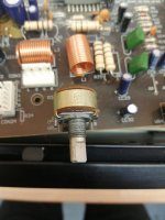
The mechanical part of the volume potentiometer on my Cambridge Audio A1 Amplifier has broken, and I'm currently trying to see if I can superglue it back together etc, but I'm not sure this will be successful, so it may be better/safer to purchase a new one.
I don't have a schematic so can't check what value it is, but hopefully the attached pics may help someone more knowledgeable advise what part I need to buy.
Thanks, Rob
I don't have a schematic so can't check what value it is, but hopefully the attached pics may help someone more knowledgeable advise what part I need to buy.
Thanks, Rob
Attachments
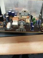
Sansui AU-9500 Channel Issue
- By Diyengineer
- Solid State
- 1 Replies
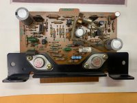
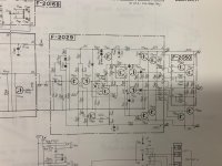
Hello,
I have a Sansui AU-9500. I noticed that one of the channels is lacking some mid frequencies making the vocals a little muddy on one channel.
Doing some troubleshooting I swapped the left and right driver boards and the problem followed. I'm not sure what I should go after on this driver board that might cause this problem.
I've attached some pics of the board and schematic for reference.
Thanks
Attachments

The addiction continues...
- Introductions
- 3 Replies
Hello All,
I've been playing with audio since I was a young kid. It's been unshakeable addiction ever since. I also started a small production company about 12 years ago that offers sound, lighting and video services. Right now my audio focus is on car audio. I started building my system about a year ago. Some nice focal speakers up front, Hertz in the rear and JL subs and amp for the lows. At the heart of the system is a DBX Driverack PA2 that's been modified to run on 12v. With the addition of the Hertz I will be needing to add at least one more DSP channel (Focal's use four channels) and am about to start down the road of SigmaStudio compatible processors
I've been playing with audio since I was a young kid. It's been unshakeable addiction ever since. I also started a small production company about 12 years ago that offers sound, lighting and video services. Right now my audio focus is on car audio. I started building my system about a year ago. Some nice focal speakers up front, Hertz in the rear and JL subs and amp for the lows. At the heart of the system is a DBX Driverack PA2 that's been modified to run on 12v. With the addition of the Hertz I will be needing to add at least one more DSP channel (Focal's use four channels) and am about to start down the road of SigmaStudio compatible processors
Adding trimpot for bias control on pioneer SX-434
- By stofbj
- Solid State
- 7 Replies
Hi, Could anyone recommend where I should install a trimpot to adjust the current on the output transistors on a pioneer sx-434, cutting the wires as per service manual is not very accurate. I know the picture is not very clear but it is all I have, thanks in advance, Happy Christmas to all.
Attachments
Marantz dv9500 muting transistors...
- By Htguy
- Digital Source
- 3 Replies
Hi,
I want to try shorting the muting transistors on my DV9500. I can find the 12v mute feed, but I need some help to make sure I don't short across the wrong transistor 🙂
I want to try shorting the muting transistors on my DV9500. I can find the 12v mute feed, but I need some help to make sure I don't short across the wrong transistor 🙂
Attachments
Series plate load resistors
- By force of 1/2
- Tubes / Valves
- 30 Replies
Hi All,
Quick, question:
For the purposes of a plate load, is there any difference between a 4k and 8k wired in series, and a single 12k resistor?
Hope this is not a ridiculous question!
Thanks in advance for you help!
Best regards,
John
Quick, question:
For the purposes of a plate load, is there any difference between a 4k and 8k wired in series, and a single 12k resistor?
Hope this is not a ridiculous question!
Thanks in advance for you help!
Best regards,
John
Motor controller on a vibraphone
- By NatJS
- Everything Else
- 4 Replies
I have an old Deagan vibraphone I'm restoring. It's an instrument made in Chicago and imported to the UK in the 70s.
I want to be able to use it in the UK (240V line voltage) without having to use a 240v > 110v transformer, which is annoying to have to lug around to gigs and also adds ti to the weight of everything I'm carrying.
The motor is this Model 0737 - K-2 Series Parallel Shaft AC Gearmotor - AC Parallel Shaft Gearmotors - Bodine Electric
In the control panel is a 1uF capacitor rated at 250vac, a VR and this adjustable voltage regulator CSR1004A | United Automation, 230 V Voltage Regulator, 10A, Adjustable 3-Pin CSR1004A | RS Components which is rated at 230vac. It's wired up as in the schematic on the controller datasheet.
Will I be able to run it directly at UK mains voltage and get it in the right speed range just by adding a resistor in series with the VR on the controller? Or am I misunderstanding how it works?
Thanks!
TDA1541A Dual differential MK1
- By batteryman
- Digital Line Level
- 51 Replies
More on my dual 1541a Rainbow_hui dac saga..
This has now been configured for differential working using a pair of Sowter 9545 transformers in MK1 test version.
Using one dac for normal and the other for inverted data operation meant just interposing a spare inverter in IC11 - a 74HC14 before pin3 of dac 2.
To prove that I had connected the transformers correctly, with both dacs receiving the same data, there was no ouput ( as good as!) as expected.
Next step is to use the dacs in simultaneous mode with one dac per channel. However this requires 2s complement to offset binary conversion and a simple method of doing so has been devised which I hope to test next week.
In the meantime more listening to be done for the consequences of the lsb error due to inverting the data. (Nothing audible with a quick listen)
I found a mistake on the pcb, the unused gates of IC11 are shown correctly as having the inputs tied to ground except that its actually pin 6 (output) that was grounded instead of pin 5.
Ianj
Questions About Bridging An Amp
- By jaagut
- Solid State
- 13 Replies
Currently there was a talk and an attempt in our local audio community to build an amp which will utilize two bridged amp to be connected again in bridge mode. Since the debate is not yet close, I would like to ask your expert opinion whether it is possible or not, or any of you has done this, or is true that Crown or any manufacturer made the bridged-bridged amp and already sold this in the market?
Combo Active/Passive crossover design
- By DIYhopeful
- Multi-Way
- 0 Replies
Hi,
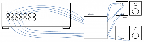
I'm currently designing my first 2 way speakers. I was torn between active and passive so I decided why not both since I love music and a surround setup for movies.
For the music setup front 2 channel:
I will be using 4 amplifier channels for the 2 mids and 2 tweeters via PC REW Jriver setup. This is strictly for the fronts.
Also I was wondering if I could create a switch box type setup for the AVR output jacks since I have one AVR and not enough amplifier channels for a surround setup with passive crossovers as well as a dedicated music (active) setup. Initially there was a switch system inside the speaker but I realized I won't need that with the switch box.
My question is, is this safe? It won't blow up on me right? Any feedback and criticism will be appreciated. I don't really know my electrics tbh.
Attachments
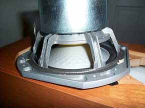
Removing Rubber Speaker Surrounds
- By CliffR52
- Construction Tips
- 11 Replies
Hi All.
I'm having a go at restoring 2 Loudspeakers.
They are of 2 way design featuring cTs Model 8W9R Woofers.
The Woofers are fitted with rubber surrounds.
To improve sensitivity I'm considering the removal of the rubber in preference to foam surrounds.
Removing deteriorated foam surrounds is straight forward.
How should I go about removing the rubber types without damaging the cones?
thanks
Cliff
Crossover question
In this article by Dick Olsher he has this crossover for the SAL fulrange driver and the Hawthorn Augie 15" woofer. The woofer just uses a first order crosover using a 5mh inductor. Then the SAL uses a 2 order crossover made from a 76uf cap and a 3mh inductor. My question is what is the crossover type and frequency used for the SAL is it a Linkwitz-Riley, Butterworth, Besel, Chebychev or some other type ?
Tip_85
Tip_85
Burson Op-Amps Vs....
First, by way of disclosure, this post was made possible by Burson Audio, who supplied me with their Classic and Vivid op-amps after I responded to a post they made elsewhere on this site. I sent those to my friend Robert, whose observations are included here, and ordered more for myself from Parts Connexion.
Second, the system(s) used for comparison: The component in which the op-amps themselves were used was a Pass DIY Whammy headphone amp. Robert's was built from the kit (by me). My Whammy was 'upscale', built with New Class D discrete regulators; Takman REY metal film resistors; Nichicon Muse FG and Elna Silmic II electrolytics outside the power supply; Jantzen Superior Z-Caps for the input coupling caps, and Vishays for the ones around the optocoupler; the pot in mine was an Audio Note Noble-style (which was also in Robert's, as opposed to ALPS in the stock kit). Phones in my case are Focal Utopias; Robert's are Audeze LCD-2s.
The source, in my case, was a DIY turntable with a Graham 2.2 arm and Soundsmith Hyperion Mk II ES cartridge fed through a Pass XP-17 phono preamp. Cables were self-terminated Gotham Audio GAC-4/1 Ultra Pro. Robert also has a DIY turntable with a very obscure arm whose name I can't recall and some Koetsu cartridge. He uses a tube phono stage whose name I also can't recall. Suffice it to say that his his system (VTL Signature MB-450 monoblocks, heavily modified Magnepan 3.6s) is the best I've ever heard outside a high-end audio store. (My system may now be equally good, due to some major pandemic-excused upgrades.)
So, to the op-amps. The various ones used for comparison were: (i) the stock op-amp supplied with the Whammy kit, which I believe is a TI part, about $1; (ii) an Analog Devices op-amp that is about $10; (iii) the Burson V6 Vivid and Classic, which tend to go for about $70; and (iv) the New Class D dual op-amp, which is about the same price as the Bursons. Unfortunately, I do not (yet!) have a SparkoS op-amp to compare.
First point: No matter which of these op-amps you use, the Whammy sounds quite good---totally listenable even with the stock part, if you hadn't heard the others. But, by comparison, the stock (presumably TI) op-amp is pretty terrible. So much so that there's no point describing the ways the other ones are better. Spend the extra $10 at the very least.
Second point: In agreement with almost everyone else who has posted about this, the Vivid is way too bright in the Whammy. It may well be that the Vivid is perfect for other circuits (ones that tend to be a bit dark). If you're replacing an op-amp in a CD player, e.g., then it may well be worth comparing the Vivid and the Classic. Once you take out the old op-amp, make sure you solder in a DIP socket, so then you can swap all kinds of things in and out until you know what's best. But, in the Whammy, as I said, the Vivid is too bright, annoyingly so.
Third point: It's a very close call between the Burson V6 Classic and the New Class D. I think if I had to have just one I'd go for the New Class D, but I've not done enough comparative listening to be really sure. I'm very happy to have both and have swapped them in and out without feeling like I was losing very much. I'm quite sure I'd be happy enough to live with the Burson Classic. Both the Burson Classic and the New Class D are fully capable of revealing details I'd not heard before, but without feeling 'etched'; i.e., they both make music sound like music and leveraging the extra detail to make the music sound MORE like music.
Reference full range or coaxial driver suggestions
- By camplo
- Full Range
- 73 Replies
Hi everyone!? I am a hobby speaker designer looking to design my own version of a FAST speaker. I've chosen a woofer, but am seeking suggestions for a mid/tweeter.
H1602-04/06 L12RE/XFC
So far this is on the top of the list. I, and others, seem to think the frequency resonse on this one isn't exactly choice but maybe doable...the power specs look right for my project. Hoping to find something with similar power/spl/size but a flatter frequency response.
Thanks for the help
Camplo
Need advice on full rage TV only DIY kits
- Multi-Way
- 7 Replies
I will be in need of new TV speakers for my living room. I will be using them for TV 90% and music 10%. They will be in phantom mode 100% of the time WITHOUT any subs. I will be using my old Yamaha AVR that is 4ohm stable for stereo, bass and treble for eq only (for now) And they must be capable of at least 40hz or lower. They will be in a corner so I’ll have to figure for a front port. I have 39” from tv to floor if I want them under the TV but I fully expect taller ones so height is not an issue as of now. I am hoping for something in a kit form rather than me trying to build xo’s. I also do not need a flat pack, I will be building all the cabs from raw material as I have built all my other cabs.
THEY MUST BE A FLOOR STANDING TOWER.

I’ve thought about the DIYSG 1099’s or HT’s but I’ll need a sub so for now that’s a no. I’ve also thought about the classic 2.5 but feel that they would not be an upgrade to what I have now. I seriously would love to build the testarossa’s but I feel they would be wasting away doing TV duty and they are a little out of my budget, the statement ll seem to be the best fit but are at the far end of my budget. FYI - I’d even consider a line array. Bonus if it’s a good off axis ribbon tweeter of some sort
Soooo..... I’m looking to spend up to $1000 for a pair of DIY kits, i am wondering if you feel it would be worth the money just for TV duty or maybe just any 5-$700 a pair towers..
Thoughts......
Thank you, Chad
For reference this is my theater so I am not in need of anything else besides what you read above, all other duty’s are covered.

THEY MUST BE A FLOOR STANDING TOWER.
I’ve thought about the DIYSG 1099’s or HT’s but I’ll need a sub so for now that’s a no. I’ve also thought about the classic 2.5 but feel that they would not be an upgrade to what I have now. I seriously would love to build the testarossa’s but I feel they would be wasting away doing TV duty and they are a little out of my budget, the statement ll seem to be the best fit but are at the far end of my budget. FYI - I’d even consider a line array. Bonus if it’s a good off axis ribbon tweeter of some sort
Soooo..... I’m looking to spend up to $1000 for a pair of DIY kits, i am wondering if you feel it would be worth the money just for TV duty or maybe just any 5-$700 a pair towers..
Thoughts......
Thank you, Chad
For reference this is my theater so I am not in need of anything else besides what you read above, all other duty’s are covered.
Can you build me a passive pre-amp?
- By davidtil
- Analog Line Level
- 13 Replies
Schiit has one for $49 but without remote. I'm old and lazy so remote volume control a must. Only listen to cd's. I do have a powered sub I want to keep using, currently fed signal at speaker level ins. So here is what I want. Remote for volume control, ONE l,r rca pair IN for cd player, ONE l,r rca pair OUT to amp, and a SINGLE rca variable out (controlled by pre-amp volume) so I can connect my powered sub with a single rca male/male interconnect, not speaker level. Easy, simple, affordable. If you won't build it but can send me a complete parts list I would appreciate it.
-
Locked
Skin Effect in Wires.
I have seen repeated references here and at AA to skin effect when explaining why esoteric wire and cables are sonically superior to regular copper wire. I have seen comments that larger diameter wire is inferior to smaller diameter wire for high frequency signals. I don't understand where these positions come from and would like someone who does to please explain how this could be so.
To start off, here is a well written explaination about skin effect (cribbed from a post from www.churchsoundcheck.com by Kenneth Reighard).
I understand this explaination and it makes sense that extremely large power bus links would be hollow because copper is expensive. Note that based on this a solid conductor of the same outside diameter would not be at a disadvantage compared to a hollow conducter as far as impedance or current carrying capacity is concerned, it would simply cost more to make.
The fact is that a larger diameter conductor is always going to have lower impedance than a smaller diameter conductor at any frequency.
Take the 20 KHz frequency for example: The skin depth is 0.5 mm (rounding off needless precision). Therefore a 1mm wire is the largest wire that will not exhibit skin effect at that frequency. A 1mm diameter wire will have a cross sectional area of PI*(0.5mm)^2 = 0.785mm^2.
A 2 mm wire will only use the outer 0.5mm of the wire to carry the 20KHz signal. This outer current carrying area's cross sectional area = PI*(1mm)^2 - PI*(0.5mm)^2 = 2.36mm^2
The ratio of current carrying cross sectional area of the two wires is 2.36/0.785 or almost exactly 3 to 1. This means that at 20 KHz the 2mm wire will have 1/3 the impedance of the 1mm wire. How could skin effect make the 1mm wire superior to the 2mm wire? The larger the wire size gets, the greater the advantage becomes for the larger wire.
Comments, rebuttals?
Phil
To start off, here is a well written explaination about skin effect (cribbed from a post from www.churchsoundcheck.com by Kenneth Reighard).
"Skin effect happens at all nonzero frequencies, and is more pronounced in better conductors such as copper and silver. Its effect is normally not noticeable unless the conductor diameter is greater than twice the skin depth for a given frequency. For most conductor sizes used in speaker cable, it is not a big issue. For AC power, it becomes an issue only in the larger wire sizes (with #2 AWG copper conductor, there is about a 1% difference between the DC resistance and 60-Hz AC resistance at 75 degrees Celsius.) The difference is about two percent for 4/0 AWG copper conductor. (At 60 Hz, the skin depth in copper is 8.6 millimeters, roughly one-third of an inch.) For very heavy busbars, such as those at generating plants and transmission substations, the busbar is hollow with a wall thickness of about 1/3 to 1/2 inch for copper, 1/2 to 3/4 inch for aluminum. The reason is that if the bar were solid, anything inside of 1/2 inch in copper, or 3/4 inch in aluminum, would carry little or no current and the material would be wasted.
The skin depth in copper at 20 KHz, the upper end of the audio band, is 0.471 millimeter. (At 20 Hz, the skin depth in copper is 14.9 millimeters; about 5/8 inch.) #18 AWG solid wire has a diameter of 1.016 mm, just slightly more than twice the skin depth at 20 KHz. Therefore, the skin effect will have a slight effect, at the upper end of the audio frequency range, in #18 wire. In heavier wire, there will be a larger cross-section at the center of the conductor that will not be used by the current flow at 20 KHz, so the ratio of 20-KHz AC resistance to DC resistance will be larger.
The skin depth is inversely proportional to the square root of the frequency. It may be calculated from:
d= sqrt(2/(omega)(mu)(sigma)), where d is the skin depth in meters, sqrt is the square-root function, omega is the radian frequency (2*pi*frequency in Hertz), mu is the permeability (for copper, approximately the same as free space, or 4*pi*10e-7 Henrys per meter; "10e-7" means ten to the negative seven power), and sigma is the conductivity in mhos per meter or Siemens per meter (reciprocal of resistivity; for copper is 5.7*10e7.) (The equation is equation 3.32b, page 51 of _Applied Electromagnetism_ by Liang Chi Shen and Jin Au Kong (Boston, MA: PWS Publishers, 1983))
I understand this explaination and it makes sense that extremely large power bus links would be hollow because copper is expensive. Note that based on this a solid conductor of the same outside diameter would not be at a disadvantage compared to a hollow conducter as far as impedance or current carrying capacity is concerned, it would simply cost more to make.
The fact is that a larger diameter conductor is always going to have lower impedance than a smaller diameter conductor at any frequency.
Take the 20 KHz frequency for example: The skin depth is 0.5 mm (rounding off needless precision). Therefore a 1mm wire is the largest wire that will not exhibit skin effect at that frequency. A 1mm diameter wire will have a cross sectional area of PI*(0.5mm)^2 = 0.785mm^2.
A 2 mm wire will only use the outer 0.5mm of the wire to carry the 20KHz signal. This outer current carrying area's cross sectional area = PI*(1mm)^2 - PI*(0.5mm)^2 = 2.36mm^2
The ratio of current carrying cross sectional area of the two wires is 2.36/0.785 or almost exactly 3 to 1. This means that at 20 KHz the 2mm wire will have 1/3 the impedance of the 1mm wire. How could skin effect make the 1mm wire superior to the 2mm wire? The larger the wire size gets, the greater the advantage becomes for the larger wire.
Comments, rebuttals?
Phil
Looking for a 2 channel Full range floor kit for TV room
- Full Range
- 8 Replies
I will be in need of new TV speakers for my living room. I will be using them for TV 90% and music 10%. They will be in phantom mode 100% of the time WITHOUT any subs. I will be using my old Yamaha AVR that is 4ohm stable for stereo, bass and treble for eq only (for now) And they must be capable of at least 40hz or lower. They will be in a corner so I’ll have to figure for a front port. I have 39” from tv to floor if I want them under the TV.
MUST BE A FLOOR STANDING TOWER.

I’ve thought about the DIYSG 1099’s or HT’s but I’ll need a sub so for now that’s a no. I’ve also thought about the classic 2.5 but feel that they would not be an upgrade to what I have now. I seriously would love to build the testarossa’s but I feel they would be wasting away doing TV duty and they are a little out of my budget. I’d even consider a line array.
Soooo..... I’m looking to spend up to $1000 for the pair if you feel it would be worth the money even for TV duty (statements ll?) or maybe just any 5-$700 a pair towers. Bonus if it’s a good off axis ribbon tweeter of some sort.
Thoughts......
Thank you, Chad
For reference this is my theater so I am not in need of anything else besides what you read above, all other duty’s are covered.

MUST BE A FLOOR STANDING TOWER.
I’ve thought about the DIYSG 1099’s or HT’s but I’ll need a sub so for now that’s a no. I’ve also thought about the classic 2.5 but feel that they would not be an upgrade to what I have now. I seriously would love to build the testarossa’s but I feel they would be wasting away doing TV duty and they are a little out of my budget. I’d even consider a line array.
Soooo..... I’m looking to spend up to $1000 for the pair if you feel it would be worth the money even for TV duty (statements ll?) or maybe just any 5-$700 a pair towers. Bonus if it’s a good off axis ribbon tweeter of some sort.
Thoughts......
Thank you, Chad
For reference this is my theater so I am not in need of anything else besides what you read above, all other duty’s are covered.
Krell KSA300S power amp.
- Solid State
- 3 Replies
I've been eyeballing this amplifier for sale here at a sale in Wisconsin. It has been thoroughly checked out. I figured that it could team up along with my 2 McIntosh mc 2500's. Seems like a well-built hardy looking amplifier.
Any Krell enthusiasts familiar with the sound quality and sturdiness of this amplifier? If so, I'd be very grateful to hear from you Krell officianados. Sincerely, Stan C.
Any Krell enthusiasts familiar with the sound quality and sturdiness of this amplifier? If so, I'd be very grateful to hear from you Krell officianados. Sincerely, Stan C.
20Hz Horn Loaded Subwoofer - built into church hall
- By googlyone
- Full Range
- 43 Replies
So for reasons that defy logical explanation, the wife and I would up owning a 130 year old, gothic revival church. This would normally have little to do with a 20Hz horn loaded sub, except that we are toying with the idea of living there.
The church itself is about 60 feet long and 20 feet wide, with transepts off to the sides of the altar that are about 6 feet deep and 11 feet wide.
One of the big challenges is that the celing height is over 30 feet at the peak. This is one huge volume of a room. And also an impressivbe one at that!

The transept that the "workbench" AKA dual horn loaded sub goes into is off to the left in this pic.
The sheer volume of the place sets a challenge in providing solid bass. At the same time this provides a few opportunities to build a speaker like I will never have the chance to do again.
The bulk of the hall is a pretty massive living room, and when at the church, my hobby desk is in one of the transepts. The Wife has given permission for me to adapt this as a "workbench". Yes, she knows there is a cunning plan to make this a giant sub.
I toyed with tapped horns, vented, sealed and infinte baffle. In the end a combination of the practicalities of generating adequate acoustic power for the space and what drivers I had laying around led to a horn loaded sub. The overwhelming factor here being the efficiency provided by a horn loaded sub.
Tapped horns do OK, but dont really help that much with cone excursion. Sealed, bented and infinite baffle work, but would reqire me to buy new drivers - and in such a room would drive me to big expensive drivers and big power mps if I were to achieve bass antwhere toward 20Hz.
So a horn it is. But I need to get a horn mouth that is ludicrously big to ger anything like decent bass toward 20Hz. So how does this work?
The transept is shown below...

Yes, that is a bed on the old altar🙂
The horn loaded sub will actually be two in mirrir image, operating either side of a workbench. The air of these will effectively turn the 1/2Pi space against the wall into a 1/4 PI space. This reduces the total mouth area required by the horn to "work" as a 20Hz horn.
This helps, but we still need a monsterous horn mouth. So what gives?
There will be a 900mm (three foot) wide section as a desk, with 1200mm (four foot) wide subs either side. The two of these will each see what is effectively 1/8 space. They will also face into the transept. This is pretty important in this design.
View attachment Horns_In_Hall.pdf
At the back of the desk there will be a panel that closes off the desk - making the area behind the desk and into the transept an integral part of the horn. After exit into the transept, the area of the horn section is effectively the area behind the horn to the rear wall of the transept. This is 330cm wide by 70Cm deep, or 23,100cm square for the pair of horns, or 11,500cm2 each. This part of the expansion is controlled by the placement of the desk, and is not "made up" by me, and is not an "optimistic guess".
This will then expand out to the width of the transept and exit into the hall at the face of the wall. This part is a bit more of an optimistic guess... but I think will realistically expand to twice the 23,000cm2 at the exge of the trsnsept.
Each of the wooden (folded) horns is far from modest. They are 1036mm deep, 1200mm wide and 800mm tall. The desk will be between these and slightly below the height of the top of the subs ) as the sub exterior height is 836mm, somewhat taller than is comfortable for a desk.
The horns themselves are characterised by:
- Drivers: Two 25 inch Richrd Allan HD15 drivers per horn
- S1 (at the horn mouth) 700cm2
- L12 280cm
- S2 (at the exit of the folded horn into the transept) 6000cm2
- Vrc (behind the drivers) 180 litres
- This is a 20Hz flare rate from the drivers to the horn mouth. The upper frequency is set by the entry from the drivers into the horn, a touch over 200Hz.
In the transept we have
- L23 - about 100cm (known and set by placement of bench)
- S3 - 11,500cm2 (area of transept behind the bench)
Then from the exit of the overall horn coupled into the transept
- L34 - the length of the transept to the hall
- S34 - 36,000 this is a bit of a guess. Admitted.
At the back of the desk, there will be a further extension of the horn into the depth of the transept, which extends the horn loaded section to the rear of the transept.
From the expansion to the back of the transept, there will be a further expansion back into the hall proper.
Lets look at the main "horns"...
View attachment Top View.pdf
The main horns are constructed from 18mm "structafloor" - basically flooring board. This is both tough, rigid and cost effective. These subs use a LOT of timber. And bracing.
The sub internal height is 800mm. All panels except the top and bottom are 800mm tall. This allowed me to get the local hardware store to rip the top and bottom off 3600mm "yellow tongue" flooring sheets to make the panels. Mind you there are 5 3600mm sheets and two 2400x1200mm sheets in these boxes. Just the timber will be way over 1/4 ton before I start!
With the drivers there is no way these things are moving around.
View attachment Top Panel Drill.pdf
I have to cut and drill all the panels before I take them into the hall. Not because I cant get them in the door (there are double doors in the belltower) but because of the weight of the things.
CAD is super helpful here.
What are drivers? The model is pretty insensitive to the drivers. I gave four old school Richard Allan HD15 drivers. Two per sub (there are reasons why I did this....) works a treat. Dropping in for example an JBL2226 gives better results, if the difference actually matters.
Looing at the response using the Richard Allan drivers... with no effort to make the plot look pretty...

This includes the path length from the mouth of the horn through to the transept and up into the hall.
And this is for 2.83V into 8 Ohms. Which is 2W per box, or four watts total input. Just goes to show the power of horn loading🙂
So what is the cone excursion like at 115dB?

This says that at 2.83V input, and close on 115dB output right down close to 20Hz, the cone excursion peaks at 1.1mm. Even witht he old school Richard Allan drivers, which I would rate to +/- 4mm or so in a "near engh to linear" region, there is miles of excursion to go. 50 watts per driver and things will be getting rather loud in the hall...
To be honest, I don't see these ever getting turned up too far, as I am worried that the old stained glass windows will vibrate too much and break. I would hate myself, and the wife would probably cut my head off and hide it inside one of the speakers. No really, she would be that angry... I would go as far as saying "without a doubt, I will go missing if I break the windows"
The timber is bought, and cut. I am currently finishing off the drilling and prep of the panels to take up to the church and screw together. In the next week or so they will be up and running.
They will be run via a DSP crossover which will allow me to program the delay required in the main speakers. The amp driving them will likely only be 50 Watts into 8 ohms - if I leave it like that I will not be tempted to crank them up🙂
The main speakers are quite high efficiency. To match the old school Richard Allan bass drivers, to match the subs, I dug out some 10 inch Richard Allan CG10's. These are about 97dB/w/m. The tweeters, high efficiency domes are running with nil attenuation to match the efficiency of the 10 inch bass mids.
This will end up being a seriously high efficiency system, and I have litle doubt, cable of some awe inspring bass in such a huge volume of a room.
The church itself is about 60 feet long and 20 feet wide, with transepts off to the sides of the altar that are about 6 feet deep and 11 feet wide.
One of the big challenges is that the celing height is over 30 feet at the peak. This is one huge volume of a room. And also an impressivbe one at that!
The transept that the "workbench" AKA dual horn loaded sub goes into is off to the left in this pic.
The sheer volume of the place sets a challenge in providing solid bass. At the same time this provides a few opportunities to build a speaker like I will never have the chance to do again.
The bulk of the hall is a pretty massive living room, and when at the church, my hobby desk is in one of the transepts. The Wife has given permission for me to adapt this as a "workbench". Yes, she knows there is a cunning plan to make this a giant sub.
I toyed with tapped horns, vented, sealed and infinte baffle. In the end a combination of the practicalities of generating adequate acoustic power for the space and what drivers I had laying around led to a horn loaded sub. The overwhelming factor here being the efficiency provided by a horn loaded sub.
Tapped horns do OK, but dont really help that much with cone excursion. Sealed, bented and infinite baffle work, but would reqire me to buy new drivers - and in such a room would drive me to big expensive drivers and big power mps if I were to achieve bass antwhere toward 20Hz.
So a horn it is. But I need to get a horn mouth that is ludicrously big to ger anything like decent bass toward 20Hz. So how does this work?
The transept is shown below...
Yes, that is a bed on the old altar🙂
The horn loaded sub will actually be two in mirrir image, operating either side of a workbench. The air of these will effectively turn the 1/2Pi space against the wall into a 1/4 PI space. This reduces the total mouth area required by the horn to "work" as a 20Hz horn.
This helps, but we still need a monsterous horn mouth. So what gives?
There will be a 900mm (three foot) wide section as a desk, with 1200mm (four foot) wide subs either side. The two of these will each see what is effectively 1/8 space. They will also face into the transept. This is pretty important in this design.
View attachment Horns_In_Hall.pdf
At the back of the desk there will be a panel that closes off the desk - making the area behind the desk and into the transept an integral part of the horn. After exit into the transept, the area of the horn section is effectively the area behind the horn to the rear wall of the transept. This is 330cm wide by 70Cm deep, or 23,100cm square for the pair of horns, or 11,500cm2 each. This part of the expansion is controlled by the placement of the desk, and is not "made up" by me, and is not an "optimistic guess".
This will then expand out to the width of the transept and exit into the hall at the face of the wall. This part is a bit more of an optimistic guess... but I think will realistically expand to twice the 23,000cm2 at the exge of the trsnsept.
Each of the wooden (folded) horns is far from modest. They are 1036mm deep, 1200mm wide and 800mm tall. The desk will be between these and slightly below the height of the top of the subs ) as the sub exterior height is 836mm, somewhat taller than is comfortable for a desk.
The horns themselves are characterised by:
- Drivers: Two 25 inch Richrd Allan HD15 drivers per horn
- S1 (at the horn mouth) 700cm2
- L12 280cm
- S2 (at the exit of the folded horn into the transept) 6000cm2
- Vrc (behind the drivers) 180 litres
- This is a 20Hz flare rate from the drivers to the horn mouth. The upper frequency is set by the entry from the drivers into the horn, a touch over 200Hz.
In the transept we have
- L23 - about 100cm (known and set by placement of bench)
- S3 - 11,500cm2 (area of transept behind the bench)
Then from the exit of the overall horn coupled into the transept
- L34 - the length of the transept to the hall
- S34 - 36,000 this is a bit of a guess. Admitted.
At the back of the desk, there will be a further extension of the horn into the depth of the transept, which extends the horn loaded section to the rear of the transept.
From the expansion to the back of the transept, there will be a further expansion back into the hall proper.
Lets look at the main "horns"...
View attachment Top View.pdf
The main horns are constructed from 18mm "structafloor" - basically flooring board. This is both tough, rigid and cost effective. These subs use a LOT of timber. And bracing.
The sub internal height is 800mm. All panels except the top and bottom are 800mm tall. This allowed me to get the local hardware store to rip the top and bottom off 3600mm "yellow tongue" flooring sheets to make the panels. Mind you there are 5 3600mm sheets and two 2400x1200mm sheets in these boxes. Just the timber will be way over 1/4 ton before I start!
With the drivers there is no way these things are moving around.
View attachment Top Panel Drill.pdf
I have to cut and drill all the panels before I take them into the hall. Not because I cant get them in the door (there are double doors in the belltower) but because of the weight of the things.
CAD is super helpful here.
What are drivers? The model is pretty insensitive to the drivers. I gave four old school Richard Allan HD15 drivers. Two per sub (there are reasons why I did this....) works a treat. Dropping in for example an JBL2226 gives better results, if the difference actually matters.
Looing at the response using the Richard Allan drivers... with no effort to make the plot look pretty...
This includes the path length from the mouth of the horn through to the transept and up into the hall.
And this is for 2.83V into 8 Ohms. Which is 2W per box, or four watts total input. Just goes to show the power of horn loading🙂
So what is the cone excursion like at 115dB?
This says that at 2.83V input, and close on 115dB output right down close to 20Hz, the cone excursion peaks at 1.1mm. Even witht he old school Richard Allan drivers, which I would rate to +/- 4mm or so in a "near engh to linear" region, there is miles of excursion to go. 50 watts per driver and things will be getting rather loud in the hall...
To be honest, I don't see these ever getting turned up too far, as I am worried that the old stained glass windows will vibrate too much and break. I would hate myself, and the wife would probably cut my head off and hide it inside one of the speakers. No really, she would be that angry... I would go as far as saying "without a doubt, I will go missing if I break the windows"
The timber is bought, and cut. I am currently finishing off the drilling and prep of the panels to take up to the church and screw together. In the next week or so they will be up and running.
They will be run via a DSP crossover which will allow me to program the delay required in the main speakers. The amp driving them will likely only be 50 Watts into 8 ohms - if I leave it like that I will not be tempted to crank them up🙂
The main speakers are quite high efficiency. To match the old school Richard Allan bass drivers, to match the subs, I dug out some 10 inch Richard Allan CG10's. These are about 97dB/w/m. The tweeters, high efficiency domes are running with nil attenuation to match the efficiency of the 10 inch bass mids.
This will end up being a seriously high efficiency system, and I have litle doubt, cable of some awe inspring bass in such a huge volume of a room.
Attachments
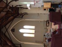
Merry merry CHristmas Ribbon :)
- By WrineX
- Planars & Exotics
- 0 Replies
🙂 well i was into making ribbons lately so i thought it would be apropiete time to wish everyone a merry Christmas (ribbon) while im at it 🙂
Merry Christmas Ribbon!!!!!! - YouTube
cyaaa !!! :0
Merry Christmas Ribbon!!!!!! - YouTube
cyaaa !!! :0
Pathos Classic one
- By priax
- Tubes / Valves
- 7 Replies
Hi,
can somebody help me with a schematic or service manual for the Pathos classic one?
thanks priax
can somebody help me with a schematic or service manual for the Pathos classic one?
thanks priax
Stetsom HL1200.04 turn on/off thump
Season greetings gents.
I just completed repair to a Stetsom HL1200.04 which had no voltage to pin 12 of the IRS2092 on both rear channels, this was troubleshooted and rectified, amplifier now passes clean audio.
however when connected to a speaker, the amplifier has a turn on and off thump. I wasn't sure if to post in the class D, but I'm looking at two avenues that may be causing the thump:
1. Does any of the capacitive components of the IRS2092 which control shutdown/mute/standby can be altered to overcome this, whilst the amplifier is being powered up and down?
2. I'm also looking at the remote turn on to the SG3525 and the soft start pin 8. can/will altering these values assist with or eliminate the turn on/off thump?
I haven't messed around much with IRS2092.
Attachments
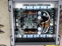
Any AMT / ribbon waveguide center speaker designs?
- By sharpi31
- Planars & Exotics
- 0 Replies
I’m hoping to build a center speaker with very limited vertical HF dispersion. My system is in a family room with wooden floors and minimal soft furnishings, and the center speaker will most likely end up sat on a low table under my wall-mounted TV (approx 300mm of table surface in front of the current speaker baffle). All in all, I know this isn’t an ideal setup, but I’d like to try something with very limited vertical dispersion to minimise the impact of table surface reflections (and also reflections from the wider room).
I’ve been looking at ribbon & AMT drivers with waveguides. I’d love to buy a Beyma TPL-150H, but the Dayton PHT1-6 seems pretty attractive for not much money.....
Due to limited vertical space a horizontal MTM is probably the only viable option. To minimise horizontal lobing I’d ideally keep the tweeter crossover frequency low, but with a ribbon / AMT / planar tweeter that’s not so easy....
I’ve searched for existing tried and tested MTM designs with these types of HF drivers, but found very little. Does anyone know of any DIY projects or kits I could read about? Many thanks in advance, and Merry Christmas!
Who needs cameras in the house?
- By Formann
- The Lounge
- 73 Replies
Can anyone explain to me one situation? I have been living in England for about two years. Sometimes I notice people install security cameras. I suppose if they do that, there are several reasons for installing such a security system. I do not even have any fire detectors in my house. Does it worth it to spend money on that? How high is the risk of being attacked by burglars? What brands can you recommend? Is the Ajax security providing company reliable? I am sorry for so many questions. I have just started to worry about my safety.
Denon DRW-660
- By shortwave
- Analogue Source
- 7 Replies
Hello. Having an issue with a Denon DRW-660 cassette tape deck.
This unit has two decks. Both decks play cassettes no issues. Both have a directional switch which changes the side being played and it operates no issues.
The problem is when engaging either fast forward or fast reverse, it starts to engage and then dis-engages and stops (both decks exhibit this trait). Any ideas? Does this unit have a auto shutdown if the amperage draw is too high for the motors or other similar built in function?
I've tried different cassettes and no changes in behavior. The issue is with the machine.
Thanks.
Bass driver rear bracing
- By Bon
- Subwoofers
- 20 Replies
Does anyone have comments on the effectiveness of bracing the woofer magnet to the rear and sides with a partial shelf brace? I did this with my last set of diy speakers and even though the I used 1" (25 mm) mdf and 3" (75 mm) baffle, and plenty of shelf braces, there was more vibration than I liked. Does bracing the woofer magnet feed more vibration into the cabinet rather than mass damping vibration? The rear panel was 2" thick and total weight 60 kg per sub cabinet. I know some commercial designs have used isolating membranes (KEF) but not everyone liked the result.
Charging coupled capacitors
- By kingfisher
- Multi-Way
- 6 Replies
I've just read a blog about charging coupled capacitors and was wondering if anyone has further information on the subject?
Kingfisher
Kingfisher
help understanding measurements
Hi all,
I've been re-visiting the crossover on one of my old 3-way builds as I didn't feel I was getting the best out of it. I was working from a combination of boxsim for simulation and physical measurements/prototypes as I modified the filter network.
I was measuring close (~30mm) to the midrange, deliberately ignoring baffle step for the time being.
I was happy with the response (red line, attached image)
Out of curiosity more than anything else I took some measurements from about a metre away. Note that this is in a garage with lots of nearby surfaces that are all hard and parallel, however the measurement was gated for the first obvious reflection.
The new measurements showed an odd extension to frequency response that would need me to crossover with the tweeter at about 6.5k rather than the original aim of around 4k.
Any ideas on how/why this is happening and if I need to worry about this?
Measuring outside isn't currently an option due to living in britain, home of rain.
I should say that I can repeat the measurements from multiple near/far positions with the same results.
I'll be putting carpet up on the walls soon enough to help dampen down the reflections in the garage.
Attachments
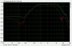
Folded Cascode - Tube, JFET or MOSFET?
- By NickKUK
- Tubes / Valves
- 23 Replies
Do you want sand in your amp? 😀 Ok back to the serious questions.
I have an tube design, that uses 6SN7 cascodes in parallel. More details here

Currently the system uses a +300.0.-300 (600V) configuration, with a folded cascode I'm hoping that can be dropped perhaps to ±240V or even less, 150.0.150 for example - providing better options for the power supply and reducing heat noise effects etc. The other benefit is the reduction in heater and real estate.
I understand JFETs and MOSFETs each have their own issues (here is a good thread detailing some) although I'm leaning towards a JFET implementation due to the flatter response curve.
Any thoughts/suggestions?
I have an tube design, that uses 6SN7 cascodes in parallel. More details here
Currently the system uses a +300.0.-300 (600V) configuration, with a folded cascode I'm hoping that can be dropped perhaps to ±240V or even less, 150.0.150 for example - providing better options for the power supply and reducing heat noise effects etc. The other benefit is the reduction in heater and real estate.
I understand JFETs and MOSFETs each have their own issues (here is a good thread detailing some) although I'm leaning towards a JFET implementation due to the flatter response curve.
Any thoughts/suggestions?
Stubbed horn?
- By Giri
- Subwoofers
- 17 Replies
What is the difference between offset horn and a stubbed horn?
I see both as options in Hornresp but a simple Google search doesn't return anything for a stubbed horn and I can't visualise what it is from the circuit diagram in Hornresp.
Clarification is much appreciated.
I see both as options in Hornresp but a simple Google search doesn't return anything for a stubbed horn and I can't visualise what it is from the circuit diagram in Hornresp.
Clarification is much appreciated.
LM4780 done and working great!
- By Decker
- Audio Sector
- 0 Replies
Just finished an LM4780 amp using the Audio Sector boards. The amp is built into a Harmon Kardon Citation 12 chassis. I am using simple MOSFET based regulators to lower the power supply voltages to the chips. The amp boards are wired in parallel mode and are used in a biamped system. It powers a pair of GPA Altec 414-8c woofers. Before putting the finished amp in the biamped system, I played it awhile into a pair of transmission line speakers ("Pass" TLs with 8 inch full range drivers) and it sounded really good. This one is a keeper. Thanks!
Loudness Circuit - Modify Pot
- By Joseph1
- Analog Line Level
- 12 Replies
How can I use a 3 pin standard volume control instead of a center tapped 4 pin one in this below circuit.
There is no any 4 pin pots nowadays.Help me to add a 3 pin one.
THanks
There is no any 4 pin pots nowadays.Help me to add a 3 pin one.
THanks
Attachments
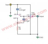
Fender 65 Princeton Reverb reissue, blown power transformer
- By ed22
- Instruments and Amps
- 4 Replies
Hello,
I'm repairing a Fender 65 Princeton Reverb reissue amp. Its power transformer has blown.
I've ordered a replacement part : Hammond 291AEX which suits this amp.
The difference is that 291AEX uses a center tap for heaters.
Looking at the schematic of the Princeton Reverb reissue :
The original power transformer doesn't use a CT for heaters.
What would be the best way to wire the new transformer?
1) Leave the CT unwired and only connect the two green wires?
2) Use the CT and take away from the PCB the two 100R resistors that creates an artificial CT? In this cas, CT sould be wired to ground point GND_420V?
3) what would happen if I leave the 2 resistors and use the CT?
thanks for your help,
rgds,
Ed
Attachments
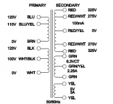
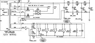
Wet Tantalum caps 1200uf 10V
- Swap Meet
- 4 Replies
FS Wet Tantalum caps 1200uf 10V
Up for sale wet Tantalum caps 1200uf 10V Military grade! Mil-Spec Sprague / Vishay
M39006/21-0021 8 Euro each. Free shipping worldwide
Datasheet
Up for sale wet Tantalum caps 1200uf 10V Military grade! Mil-Spec Sprague / Vishay
M39006/21-0021 8 Euro each. Free shipping worldwide
Datasheet
Attachments
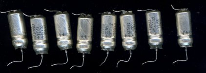
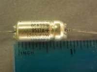
Valve/Tube etched ARBI.
- By palace
- Tubes / Valves
- 3 Replies
I have a pair of 9 pin valves, small round chrome getter on a copper post,14mm grey plates, copper wire to the pins. I believe they are American 12AX7 possibly RCA no markings other than ARBI. the full stop is also etched in to the glass, the ARBI. letters fascinate me can anyone confirm that valves used in the American space program were marked ARBI. as I believe I read years ago or is there a different explanation please.
SoundMagus X3500 output driver IC
- By Maxikill97
- Car Audio
- 2 Replies
Hi there guys,
Does anybody know the replacement IC for the output PWM of this driver board?
In an other post I saw this IC could be a 45ccdkk. Which I can't get from my suppliers and seems to be a pretty unknown IC according to google.
Does anybody has a good alternative or know the correct IC type?
This is the output PWM which is going to the optocoupler board.
I changed all the drive transistors between the Optocoupler board and the PWM driver board. The components on the pwm driver board read normal. So I suspect the IC to be defect.
Attachments
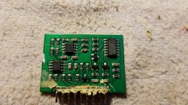
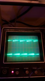
Load more
Projects by fanatics, for fanatics
Get answers and advice for everyone wanting to learn the art of audio.
Join the Community
507,772
Members
7,887,869
Messages