So for reasons that defy logical explanation, the wife and I would up owning a 130 year old, gothic revival church. This would normally have little to do with a 20Hz horn loaded sub, except that we are toying with the idea of living there.
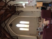
The church itself is about 60 feet long and 20 feet wide, with transepts off to the sides of the altar that are about 6 feet deep and 11 feet wide.
One of the big challenges is that the celing height is over 30 feet at the peak. This is one huge volume of a room. And also an impressivbe one at that!

The transept that the "workbench" AKA dual horn loaded sub goes into is off to the left in this pic.
The sheer volume of the place sets a challenge in providing solid bass. At the same time this provides a few opportunities to build a speaker like I will never have the chance to do again.
The bulk of the hall is a pretty massive living room, and when at the church, my hobby desk is in one of the transepts. The Wife has given permission for me to adapt this as a "workbench". Yes, she knows there is a cunning plan to make this a giant sub.
I toyed with tapped horns, vented, sealed and infinte baffle. In the end a combination of the practicalities of generating adequate acoustic power for the space and what drivers I had laying around led to a horn loaded sub. The overwhelming factor here being the efficiency provided by a horn loaded sub.
Tapped horns do OK, but dont really help that much with cone excursion. Sealed, bented and infinite baffle work, but would reqire me to buy new drivers - and in such a room would drive me to big expensive drivers and big power mps if I were to achieve bass antwhere toward 20Hz.
So a horn it is. But I need to get a horn mouth that is ludicrously big to ger anything like decent bass toward 20Hz. So how does this work?
The transept is shown below...

Yes, that is a bed on the old altar")
The horn loaded sub will actually be two in mirrir image, operating either side of a workbench. The air of these will effectively turn the 1/2Pi space against the wall into a 1/4 PI space. This reduces the total mouth area required by the horn to "work" as a 20Hz horn.
This helps, but we still need a monsterous horn mouth. So what gives?
There will be a 900mm (three foot) wide section as a desk, with 1200mm (four foot) wide subs either side. The two of these will each see what is effectively 1/8 space. They will also face into the transept. This is pretty important in this design.
View attachment Horns_In_Hall.pdf
At the back of the desk there will be a panel that closes off the desk - making the area behind the desk and into the transept an integral part of the horn. After exit into the transept, the area of the horn section is effectively the area behind the horn to the rear wall of the transept. This is 330cm wide by 70Cm deep, or 23,100cm square for the pair of horns, or 11,500cm2 each. This part of the expansion is controlled by the placement of the desk, and is not "made up" by me, and is not an "optimistic guess".
This will then expand out to the width of the transept and exit into the hall at the face of the wall. This part is a bit more of an optimistic guess... but I think will realistically expand to twice the 23,000cm2 at the exge of the trsnsept.
Each of the wooden (folded) horns is far from modest. They are 1036mm deep, 1200mm wide and 800mm tall. The desk will be between these and slightly below the height of the top of the subs ) as the sub exterior height is 836mm, somewhat taller than is comfortable for a desk.
The horns themselves are characterised by:
- Drivers: Two 25 inch Richrd Allan HD15 drivers per horn
- S1 (at the horn mouth) 700cm2
- L12 280cm
- S2 (at the exit of the folded horn into the transept) 6000cm2
- Vrc (behind the drivers) 180 litres
- This is a 20Hz flare rate from the drivers to the horn mouth. The upper frequency is set by the entry from the drivers into the horn, a touch over 200Hz.
In the transept we have
- L23 - about 100cm (known and set by placement of bench)
- S3 - 11,500cm2 (area of transept behind the bench)
Then from the exit of the overall horn coupled into the transept
- L34 - the length of the transept to the hall
- S34 - 36,000 this is a bit of a guess. Admitted.
At the back of the desk, there will be a further extension of the horn into the depth of the transept, which extends the horn loaded section to the rear of the transept.
From the expansion to the back of the transept, there will be a further expansion back into the hall proper.
Lets look at the main "horns"...
View attachment Top View.pdf
The main horns are constructed from 18mm "structafloor" - basically flooring board. This is both tough, rigid and cost effective. These subs use a LOT of timber. And bracing.
The sub internal height is 800mm. All panels except the top and bottom are 800mm tall. This allowed me to get the local hardware store to rip the top and bottom off 3600mm "yellow tongue" flooring sheets to make the panels. Mind you there are 5 3600mm sheets and two 2400x1200mm sheets in these boxes. Just the timber will be way over 1/4 ton before I start!
With the drivers there is no way these things are moving around.
View attachment Top Panel Drill.pdf
I have to cut and drill all the panels before I take them into the hall. Not because I cant get them in the door (there are double doors in the belltower) but because of the weight of the things.
CAD is super helpful here.
What are drivers? The model is pretty insensitive to the drivers. I gave four old school Richard Allan HD15 drivers. Two per sub (there are reasons why I did this....) works a treat. Dropping in for example an JBL2226 gives better results, if the difference actually matters.
Looing at the response using the Richard Allan drivers... with no effort to make the plot look pretty...

This includes the path length from the mouth of the horn through to the transept and up into the hall.
And this is for 2.83V into 8 Ohms. Which is 2W per box, or four watts total input. Just goes to show the power of horn loading
So what is the cone excursion like at 115dB?

This says that at 2.83V input, and close on 115dB output right down close to 20Hz, the cone excursion peaks at 1.1mm. Even witht he old school Richard Allan drivers, which I would rate to +/- 4mm or so in a "near engh to linear" region, there is miles of excursion to go. 50 watts per driver and things will be getting rather loud in the hall...
To be honest, I don't see these ever getting turned up too far, as I am worried that the old stained glass windows will vibrate too much and break. I would hate myself, and the wife would probably cut my head off and hide it inside one of the speakers. No really, she would be that angry... I would go as far as saying "without a doubt, I will go missing if I break the windows"
The timber is bought, and cut. I am currently finishing off the drilling and prep of the panels to take up to the church and screw together. In the next week or so they will be up and running.
They will be run via a DSP crossover which will allow me to program the delay required in the main speakers. The amp driving them will likely only be 50 Watts into 8 ohms - if I leave it like that I will not be tempted to crank them up
The main speakers are quite high efficiency. To match the old school Richard Allan bass drivers, to match the subs, I dug out some 10 inch Richard Allan CG10's. These are about 97dB/w/m. The tweeters, high efficiency domes are running with nil attenuation to match the efficiency of the 10 inch bass mids.
This will end up being a seriously high efficiency system, and I have litle doubt, cable of some awe inspring bass in such a huge volume of a room.
The church itself is about 60 feet long and 20 feet wide, with transepts off to the sides of the altar that are about 6 feet deep and 11 feet wide.
One of the big challenges is that the celing height is over 30 feet at the peak. This is one huge volume of a room. And also an impressivbe one at that!
The transept that the "workbench" AKA dual horn loaded sub goes into is off to the left in this pic.
The sheer volume of the place sets a challenge in providing solid bass. At the same time this provides a few opportunities to build a speaker like I will never have the chance to do again.
The bulk of the hall is a pretty massive living room, and when at the church, my hobby desk is in one of the transepts. The Wife has given permission for me to adapt this as a "workbench". Yes, she knows there is a cunning plan to make this a giant sub.
I toyed with tapped horns, vented, sealed and infinte baffle. In the end a combination of the practicalities of generating adequate acoustic power for the space and what drivers I had laying around led to a horn loaded sub. The overwhelming factor here being the efficiency provided by a horn loaded sub.
Tapped horns do OK, but dont really help that much with cone excursion. Sealed, bented and infinite baffle work, but would reqire me to buy new drivers - and in such a room would drive me to big expensive drivers and big power mps if I were to achieve bass antwhere toward 20Hz.
So a horn it is. But I need to get a horn mouth that is ludicrously big to ger anything like decent bass toward 20Hz. So how does this work?
The transept is shown below...
Yes, that is a bed on the old altar
The horn loaded sub will actually be two in mirrir image, operating either side of a workbench. The air of these will effectively turn the 1/2Pi space against the wall into a 1/4 PI space. This reduces the total mouth area required by the horn to "work" as a 20Hz horn.
This helps, but we still need a monsterous horn mouth. So what gives?
There will be a 900mm (three foot) wide section as a desk, with 1200mm (four foot) wide subs either side. The two of these will each see what is effectively 1/8 space. They will also face into the transept. This is pretty important in this design.
View attachment Horns_In_Hall.pdf
At the back of the desk there will be a panel that closes off the desk - making the area behind the desk and into the transept an integral part of the horn. After exit into the transept, the area of the horn section is effectively the area behind the horn to the rear wall of the transept. This is 330cm wide by 70Cm deep, or 23,100cm square for the pair of horns, or 11,500cm2 each. This part of the expansion is controlled by the placement of the desk, and is not "made up" by me, and is not an "optimistic guess".
This will then expand out to the width of the transept and exit into the hall at the face of the wall. This part is a bit more of an optimistic guess... but I think will realistically expand to twice the 23,000cm2 at the exge of the trsnsept.
Each of the wooden (folded) horns is far from modest. They are 1036mm deep, 1200mm wide and 800mm tall. The desk will be between these and slightly below the height of the top of the subs ) as the sub exterior height is 836mm, somewhat taller than is comfortable for a desk.
The horns themselves are characterised by:
- Drivers: Two 25 inch Richrd Allan HD15 drivers per horn
- S1 (at the horn mouth) 700cm2
- L12 280cm
- S2 (at the exit of the folded horn into the transept) 6000cm2
- Vrc (behind the drivers) 180 litres
- This is a 20Hz flare rate from the drivers to the horn mouth. The upper frequency is set by the entry from the drivers into the horn, a touch over 200Hz.
In the transept we have
- L23 - about 100cm (known and set by placement of bench)
- S3 - 11,500cm2 (area of transept behind the bench)
Then from the exit of the overall horn coupled into the transept
- L34 - the length of the transept to the hall
- S34 - 36,000 this is a bit of a guess. Admitted.
At the back of the desk, there will be a further extension of the horn into the depth of the transept, which extends the horn loaded section to the rear of the transept.
From the expansion to the back of the transept, there will be a further expansion back into the hall proper.
Lets look at the main "horns"...
View attachment Top View.pdf
The main horns are constructed from 18mm "structafloor" - basically flooring board. This is both tough, rigid and cost effective. These subs use a LOT of timber. And bracing.
The sub internal height is 800mm. All panels except the top and bottom are 800mm tall. This allowed me to get the local hardware store to rip the top and bottom off 3600mm "yellow tongue" flooring sheets to make the panels. Mind you there are 5 3600mm sheets and two 2400x1200mm sheets in these boxes. Just the timber will be way over 1/4 ton before I start!
With the drivers there is no way these things are moving around.
View attachment Top Panel Drill.pdf
I have to cut and drill all the panels before I take them into the hall. Not because I cant get them in the door (there are double doors in the belltower) but because of the weight of the things.
CAD is super helpful here.
What are drivers? The model is pretty insensitive to the drivers. I gave four old school Richard Allan HD15 drivers. Two per sub (there are reasons why I did this....) works a treat. Dropping in for example an JBL2226 gives better results, if the difference actually matters.
Looing at the response using the Richard Allan drivers... with no effort to make the plot look pretty...
This includes the path length from the mouth of the horn through to the transept and up into the hall.
And this is for 2.83V into 8 Ohms. Which is 2W per box, or four watts total input. Just goes to show the power of horn loading
So what is the cone excursion like at 115dB?
This says that at 2.83V input, and close on 115dB output right down close to 20Hz, the cone excursion peaks at 1.1mm. Even witht he old school Richard Allan drivers, which I would rate to +/- 4mm or so in a "near engh to linear" region, there is miles of excursion to go. 50 watts per driver and things will be getting rather loud in the hall...
To be honest, I don't see these ever getting turned up too far, as I am worried that the old stained glass windows will vibrate too much and break. I would hate myself, and the wife would probably cut my head off and hide it inside one of the speakers. No really, she would be that angry... I would go as far as saying "without a doubt, I will go missing if I break the windows"
The timber is bought, and cut. I am currently finishing off the drilling and prep of the panels to take up to the church and screw together. In the next week or so they will be up and running.
They will be run via a DSP crossover which will allow me to program the delay required in the main speakers. The amp driving them will likely only be 50 Watts into 8 ohms - if I leave it like that I will not be tempted to crank them up
The main speakers are quite high efficiency. To match the old school Richard Allan bass drivers, to match the subs, I dug out some 10 inch Richard Allan CG10's. These are about 97dB/w/m. The tweeters, high efficiency domes are running with nil attenuation to match the efficiency of the 10 inch bass mids.
This will end up being a seriously high efficiency system, and I have litle doubt, cable of some awe inspring bass in such a huge volume of a room.
Attachments
Last edited:
Funny, my wife and I have looked at a few churches turned into houses, an interesting idea to be certain.
I'm not sure 50w will be enough, you're moving a lot of cone and air, and may need more power to ensure plenty of headroom for big transients.
I think your plan to use DSP is absolutely spot on. This gives you the control you will very likely need to dial the sub in to perform as you want.
Very exciting project!
Cheers,
Gable
Why not some 18 inch subs:
I already have an 18 inch sub in there hooked up to the TV amp (out of the pic). I guess this build is not about what is essential - more:
- Because I could
- To find a real application for the stack of drivers I have
- To see if (show that) that the real thing works as HornResp says it will.
Keeping the place warm
Yep, even though we are in Australia keeping this place warm is hard work.
Winters here go down to overnight minimums of about zero Celsius (32F) and daytime 10C. Think SoCal climate. We have a 10KW reverse cycle heater in there which after three days keeps the chill off, but is certainly not "warm" in the coldest parts of winter. The power bill is awesome.
50W will not be enough
If we were talking about a conventional sub, I would agree.
50W into this thing will deliver 127dB and cone excursion peaking at 6mm at 20Hz, and falling rapidly with frequency.
Below is the predicted SPL at 50W into 4 Ohms i.e. 14VRMS.

And the cone excursion doing this:

This is worlds apart from a conventional ported sub. I know, I have built dozens of the things. The obvious price being that this consumes about 6 cubic metres.
Acoustics in the hall
Will be far from ideal. Originally the hall was full of pews (and pigeon poo). It was reverberant in a way that might sound cool for a church service, but did not bode well for music.
We now have a load of carpets - in fact several loads of them - and a lot of big recliner chairs and lounge suite. Plus a bed. This has damped the reverberation somewhat, but it will never be ideal. There will obviously be some long delays in the timing of reverb...
I already have an 18 inch sub in there hooked up to the TV amp (out of the pic). I guess this build is not about what is essential - more:
- Because I could
- To find a real application for the stack of drivers I have
- To see if (show that) that the real thing works as HornResp says it will.
Keeping the place warm
Yep, even though we are in Australia keeping this place warm is hard work.
Winters here go down to overnight minimums of about zero Celsius (32F) and daytime 10C. Think SoCal climate. We have a 10KW reverse cycle heater in there which after three days keeps the chill off, but is certainly not "warm" in the coldest parts of winter. The power bill is awesome.
50W will not be enough
If we were talking about a conventional sub, I would agree.
50W into this thing will deliver 127dB and cone excursion peaking at 6mm at 20Hz, and falling rapidly with frequency.
Below is the predicted SPL at 50W into 4 Ohms i.e. 14VRMS.
And the cone excursion doing this:
This is worlds apart from a conventional ported sub. I know, I have built dozens of the things. The obvious price being that this consumes about 6 cubic metres.
Acoustics in the hall
Will be far from ideal. Originally the hall was full of pews (and pigeon poo). It was reverberant in a way that might sound cool for a church service, but did not bode well for music.
We now have a load of carpets - in fact several loads of them - and a lot of big recliner chairs and lounge suite. Plus a bed. This has damped the reverberation somewhat, but it will never be ideal. There will obviously be some long delays in the timing of reverb...
Does that place have a basement? If you were not so attached to the flooring at the top area with steps, I would put an IB subwooder venting into the basement. I have IB vented into the ceiling with some pro 18 inch woofers and find 25 watts (two channels) at 16 hz is all I can really handle or desire.
Daqvin,
One thing that Australia is very different to the US on is basements. They are not a thing in this country. Go figure.
Old buildings (i.e. OLD) often have a cellar, but basements not so much. This place has a miniscule cellar in the front room where the priest changed - for the altar wine I guess. Well - wine in the cellar is one thing that will continue with this place!
This place is like many old buildings - local stone laid as "foundations" for the hardwood bearers. I suspect that if I dug below the stone "foundations" I would find they are less than 12" deep and only go as far as solid rock.
At one end the bearers for the floor would not be more than 12" above the dirt.
IB is the one type of speaker that I have not built. It wold certainly have been tempting if there was a decent cellar.
20Hz Horn loaded sub build
Well the timber is bought and prepped. There is a metric shitload of it!
It also weighs, well lots.
Five sheets of structafloor = 200kg plus Two sheets of MDF = 80kg. There are very few offcuts, but I imagine there is 10 or 20kg of dust in the back yard now
I got the local hardware store to do the worst of the cuts, but they will only cut right angles. It was up to me to deal with all the angled cuts. That's fine as I enjoy getting out with the power tools.

That is the top of one of the main sub boxes in the pic. The main subs are 1038mm deep by 1179mm wide. They will be 836mm tall.
This does lead to some ungainly panels to move around, and once built the carcasses will weight close on 140kg plus drivers. Plus about 200 screws

Because we dont live at the church all the time, my tools there are really focussed on the building and maintenance work we have been doing. For that reason I have done ALL the cutting, drilling and prep work at home in Adelaide and have driven the wood up here.
That went as far as installing the captive nuts for mounting the drivers.
As an engineer I suffer that dangerous mix of reliance on CAD tools and trust in the design. In this case it is essential, as just hacking out these boxes would never fly. The difference here is that at work I have a team of OCD type people to check my work before it goes into build.
I have to say that I have drunk a lot of coffee and stared at the drawings for a few hours - as I do not want a quarter of a ton white elephant at the end of this! (let alone the dollar value of wood).

This timber I reckon half filled the tray of the ute.

Well at least this lot holds the back tyres to the ground well! (Any Aussie reading this who owns this sort of car will sympathise with this!)
And loaded into the entry of the church hall ready for me to come and screw it together next week.

Yes that timber next to the door is 1178mm tall. And yes that door is ridiculous.

Well the timber is bought and prepped. There is a metric shitload of it!
It also weighs, well lots.
Five sheets of structafloor = 200kg plus Two sheets of MDF = 80kg. There are very few offcuts, but I imagine there is 10 or 20kg of dust in the back yard now
I got the local hardware store to do the worst of the cuts, but they will only cut right angles. It was up to me to deal with all the angled cuts. That's fine as I enjoy getting out with the power tools.
That is the top of one of the main sub boxes in the pic. The main subs are 1038mm deep by 1179mm wide. They will be 836mm tall.
This does lead to some ungainly panels to move around, and once built the carcasses will weight close on 140kg plus drivers. Plus about 200 screws
Because we dont live at the church all the time, my tools there are really focussed on the building and maintenance work we have been doing. For that reason I have done ALL the cutting, drilling and prep work at home in Adelaide and have driven the wood up here.
That went as far as installing the captive nuts for mounting the drivers.
As an engineer I suffer that dangerous mix of reliance on CAD tools and trust in the design. In this case it is essential, as just hacking out these boxes would never fly. The difference here is that at work I have a team of OCD type people to check my work before it goes into build.
I have to say that I have drunk a lot of coffee and stared at the drawings for a few hours - as I do not want a quarter of a ton white elephant at the end of this! (let alone the dollar value of wood).
This timber I reckon half filled the tray of the ute.
Well at least this lot holds the back tyres to the ground well! (Any Aussie reading this who owns this sort of car will sympathise with this!)
And loaded into the entry of the church hall ready for me to come and screw it together next week.
Yes that timber next to the door is 1178mm tall. And yes that door is ridiculous.
A very interesting project
Would you mind me asking roughly where the church is? I live in Adelaide too so I’m curious
I must also admit to having a soft spot for Richard Allan drivers - I had a few CG10T and they gave me my first taste of what higher sensitivity, “larger” diaphragm (relatively speaking) drivers could do. They weren’t the last word in treble extension, but what they did do was made real music.
I love deep bass too, particularly pipe organ music, so this thread will be of great interest.
Cheers,
Matt.
Awesome progress so far, and excellent choice in material transport. The Holden Maloo is high on my list of cars I want to drive some day.
Are you going to glue the panels together, as well as screws?
Considering their size and weight, I would do as you are, assemble them in place. Moving those around would be quite some effort!
Cheers,
Gable
Are you going to glue the panels together, as well as screws?
Considering their size and weight, I would do as you are, assemble them in place. Moving those around would be quite some effort!
Cheers,
Gable
I will definitely be using glue and screws. To be sure there are screws every 100mm, so about 200 or so in each box. There is also a good pile of 19*42mm timber for bracing.
These things will probably never see more than a couple of watts, but I only know one way to build things.
There are also braces right along the inside of the horn, they don't really come out in the 2D drawings, but they are there.
Yep the Maloo is a barrel of laughs to drive, and also practical. I have added a supercharger to the LS3 engine. Probably as much logic behind that as this whole speaker concept!
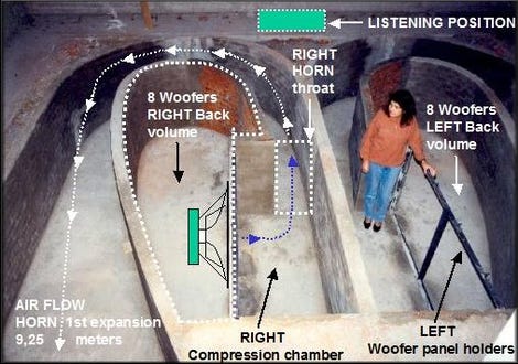
Cool project! Very impressive indeed. About the only thing more impressive is the built-in basement horn sub here:
Horn Subwoofer Takes Up Crazy Man's Entire Basement
Horn Subwoofer Takes Up Crazy Man's Entire Basement
The church is in Saddleworth, about 100km north of town - along Burra road from the service station.
It is hard to miss, big and very Gothic looking.
Once I have done with this if you want to see them drop me a line.
Thanks for that, much appreciated. Following your build with interest!
Matt.
Sounds like you've never driven a ute with more than about 100KW. Even my 180KW 2WD Hilux is a handful. I can't imagine what a supercharged V8 would be like.
I may have been a little unclear, but I’ve had traction issues many a time. Must be a bloke thing
XRK... Yes, I had seen that underfloor sub. It is an awesome effort, and provides me reassurance that I have not totally taken leave of the plot.
That rear chamber has always fascinated me - it is really quite large. I have never seen the design details on it - though I guess if there are 8 big woofers in there it is a lot smaller than it looks.
It will certainly keep his DSP bust aligning the output of that with the mains
That rear chamber has always fascinated me - it is really quite large. I have never seen the design details on it - though I guess if there are 8 big woofers in there it is a lot smaller than it looks.
It will certainly keep his DSP bust aligning the output of that with the mains
Note: Utterly tenuous link to the sub.... apart from how to move it around fast!
Subsonic, yep. It is kind of essential when you change an engine this much.
View attachment car.pdf
At the wheels the thing is just north of 400kW using rollers, which is well north of 460KW in "engine" terms.
The real thing though is the torque is more or less flat from 2500 RPM through 6500 RPM, starting at 700 nm and peaking at 800 odd. This means that driving the thing is so easy it is ridiculous. In 4th gear on an open road it is a joy.
In 1st and 2nd gear, you need to be very careful with the throttle, else everything gets very unstuck.
Last edited:
- Status
- This old topic is closed. If you want to reopen this topic, contact a moderator using the "Report Post" button.
- Home
- Loudspeakers
- Full Range
- 20Hz Horn Loaded Subwoofer - built into church hall