Aleph J power amp. boards

Hello, I'm fairly new to building my own audio equipment and I'm interested in purchasing the Aleph J power amplifier boards. In addition I was going to purchase the softstart and speaker turn-on delay/dc protector combo. Here's my question : Can I use just 1 (one) softstart and speaker turn-on delay/dc protector combo with the Aleph J power boards or does it require 2 (one for each channel of the power amplifier.?.Also, can I use just 1 (one) universal power supply board to power both channels of the Aleph J power boards or would I need a separate universal power supply to power each channel of the power amp. A response is appreciated.

Klang + ton Array Mini

Haven't posted in a long while, small children are a trip.
For my birthday present I'm going to build myself some speakers.

I really like these: Klang und ton Array Mini's. Unfortunately I can't really find much about them online aside from the original article/plans/diagram. No forum threads or anything deeper.

Two Q's (please bear in mind I'm a carpenter I can really do boxes but not circuits):

1: How do I (can I?) increase the impedance? 3 ohms will roast my old Yamaha receiver for sure. Ideally I'd like to pair them to a small passive subwoofer run off the B speaker posts on the same reciever eventually so 8 ohms would be clutch. Is this too complex of a modification?

2. Are these dumb? I like them for their size and ratios and aesthetic. I assume k+t knows what their doing and wouldn't publish a speaker that would sound rubbish. But nobody seems to have ever built them and posted about it.

Beyma 15kx box recommendatio.

Hello, just wondering if anyone has used the beyma 15kx coaxials?
What I am needing is recommendations for what box volume and port size is needed. What i need is something that will be wall mounted behind a acoustically transparent screen for home theater. I need the box as shallow as possible probably no deeper than @250mm external depth. I will use 3 of these drivers in separate enclosures for LCR. Thx
Beyma 15KX | Manualzz

21" versus quad 10" or quad 12"

I'm contemplating building speakers with a giant horn on the front, and big wooferage, ideally out of sight on the back. They would be maybe 24" wide...meaning large enough to fit a 21" woofer, which are from $300ish at Parts Express.

Alternatives would be quad 10" or maybe quad 12" - ah it's good to have choices in this life!

What thoughts do you have about these alternatives? Particulary if the budget was kept at $300ish per 4x10 or 4x12? (But comments don't have to be limited to those scenarios, blurt anything that comes to mind!)

Help modeling a JBL HF driver, 2425, from measurements

For creating an electrical model in LTspice, I am confused regarding calculating the resonance Q out of driver measurements. I need this to get the correct Ls and Cs to model the resonances.

I'd like to create accurate models so I can easier calculate starting values for the XO. (To be adjusted of course in the real life speaker, but when ordering the parts it would be nice to be in the ball park).

My example driver:
So I have 16ohm variant of the JBL 2425, a HF compression driver. I measured the impedance while they were in the horn I got with them. The lowest resonance I guess is the driver's resonance, while the peak just above 1kHz is due to the horn's cut-off frequency. ?
So to design a crossover I would like to model the drivers. I also want to
reduce or even eliminate the two impedance peaks below the cross over frequency (XO undecided but > 2kHz).

Or is that not a good idea, to insert a network to compensate for the resonance peaks? I think it is because the impedance peaks will mess up my cross over network. If I design the cross over for a 16ohm impedance (11ohm measured, so I will use that value) I will end with certain values for the cap and inductor. But the 24 ohm and 40 ohm hump will shift the cross over points down a bit and the humps should therefore be reduced. Or am I over complicating?

When looking at the measurements the 40ohm peak at 480Hz looks to have a Q of about 2. (3dB bandwidth ca 200Hz, and 480Hz/200Hz=2.4) If trying to simulate an LCR using values of R=40 ohms, Q = 2, and frequency of 480Hz, I get L=26.5mH and C=4.1uF. But simulating this in LTspice gives a much too low peak.
Using a lower Q value the peaks tighten up and look more correct. Isn't this the opposite of what should happen? Higher Q should give higher and sharper resonance peak...?
Using Q=0.25 I get L=3.3mH and C=33uF, and the resoance looks pretty correct. But that was from much trial and error, not understanding anything...

My other question is: When calculating the series LCR to be placed in parallel with the driver, to compensate/eliminate the impedance peaks, do I use the driver's nominal impedance of 16 ohms (11ohms in my case), or do I use the measured impedance at the peaks, 24 and 40 ohms?

I want a flat impedance of 11 ohms over the entire band, so I will start off with R=11ohms, and I suppose that means the L and C needs to be matched to 11ohms, and not the 40ohms measured at the resonance. ?

EDIT: Brain-fart... If I want a flat 11ohms, I need to concider the LCR network will be in parallel with the driver, and the driver itself is ca 11ohms. So my network in parallel must have much higher value for the R... hmm perhaps I will just not have this complicated network, I seem to only confuse myself the more I think about it...

Sorry for confusing questions. How would I go about creating a model out of this measurement?

Attachments

  • JBL2425J16ohm.png
    JBL2425J16ohm.png
    96.6 KB · Views: 172

Problem with old vintage russian amplifier мощности п70

Problem with old vintage russian amplifier мощности п70

Problem with old vintage russian amplifier мощности п70
Helo,guys ! In attached diagram I have following problems:
1. Channel no.1 is working well , no.2 is overloaded (huge idle current with R76, R77,R82 factory setting). R82 is variable resistor, not fixed.
2. All 3 T18 pins have 39V
3.T18 pulled out and checked - ok
4. T18 back onboard, wire 23 and 25 disconnected - still 39V all 3 pins
5. Both channels will smoke R77 or R31 if adjusted nearby their end.
6. All T16,T17,T19,T18,T20 checked, all ok.
Did'n ckecked T19 and T20 connections, maybe mixed by some guy , T19 and T20 are previously replaced by KT 809 by other hands.
Did'n ckecked T15 and ahead.
Thks in advance.

Attachments

  • russian vintage P70-05.png
    russian vintage P70-05.png
    910.6 KB · Views: 130

Starting again. LM3886 build.

Hello there

Well after several years missing in action I have found my way back here.

Previously I had planned and built an LM3876 pair of amps. Sadly all this was lost before it could be completed. Though working they needed an enclosure and proper speakers needed building.

So here I am again. No idea what my previous account name was but luckily I have found a few bits on a back up HDD.

I am hoping to be able to use my PCB patterns for this build. Though designed to suit the LM3876 it appears, with a minor change, that the LM3886 can be slipped into place. The main change being to connect pin 5 to +ve.

At the time of conception I had a lot of help, I remember, from AndrewT. Sadly I see he has passed on in the Intervening years. Rest well and thank you for all your help to the community and myself Andrew.


Here are the main parts I have recovered. The PSU PCB and associated regulators will need redoing. But that’s all.

Regards

Audible Click.

Attachments

  • 8A85EABA-F433-4C65-B21F-FA2EF5373A14.jpeg
    8A85EABA-F433-4C65-B21F-FA2EF5373A14.jpeg
    226.8 KB · Views: 649
  • LM3876_Parts_List.pdf
    LM3876_Parts_List.pdf
    65.8 KB · Views: 81
  • Wiring2.png
    Wiring2.png
    28.8 KB · Views: 648

Bridging a Son of Zen style amp?

Hello All. First and foremost, I am not sure I am posting in the right forum. I based my circuit off the son of zen and Mr. Pass's talks, so I think this counts. If not, I apologize in advance.

In any case, I am wondering if it is possible to bridge a son of zen style amplifier.

I am working on a sort of upside down son of zen amp with aleph 5 kind of power. It will work for my current speakers, but if I ever end up getting magnepans, I would love to build a second one of these and use it as a mono block.

Here is a super simplified version of my circuit.

Attachments

  • bridged amp.png
    bridged amp.png
    43.7 KB · Views: 196

Please,!, Help picking slim 2.5 or 3-way design kit

Please, please, please help.... I am so overthinking things, I have decided this is the only way to convince me which speaker design / kit to build - YOU. This is mostly because I cannot hear any of these kits so I am relying on you to guide me to a quality kit that will sound great.... not just okay (within my budget).

I am looking for a kit to build because I do not want to deal with xo design. EVERYTHING else is buildable and re-designable for me and my abilities.

Budget is $1000 for a finished project but I can easily bump that up if sound quality will be a noticeable gain.

I need a tweeter on top design
I need it to play to at least 40hz +/-
I need it less than 40” (but I can redesign the lower section if necessary to fit under my tv).

I would like a narrow design but I would be okay with a side fire woofer too.
I would like a three way design (I’m pretty sure?)

It will be in a corner (front / side port?)
It will be powered by an AVR 4 ohm stable
Phantom mode
No sub
large room
Tv and some music.

IMG_3983.jpg


FYI- I have been scouring internet for the last week so please do not recommend a website, Please recommended a speaker kit.

Or is there another route I haven’t found that doesn’t involve xo building / science-ing?

Thank you, Chad

Ceramic Speaker enclosures

In the past year I have become skilled at throwing forms on the potter's wheel. I want to make a speaker enclosure out of clay.
The ideal shape of a speaker enclosure is a shpere. I could make a round shape easily on the wheel, make a perfectly flat space to mount the driver at top, and presto! I have a round speaker enclosure. I can stand it on some legs so the woofer faces forward. I can even make a little enclosure for a tweeter or mid, attatch to two shapes, and stagger for time alignment. Many possibilities. What do you think?
-andy

New 15 " Scan Speak transducer with elliptical VC

TG's latest report features a new Scan Speak speaker with an elliptical voice coil, this time a 15-inch twoofer driver.
It is interesting to read the opinions about it when the first model came out:

ScanSpeak-Ellipticor-1


" The aim of elliptical voice coils is obviously to break symmetry. The force applied to the cone through the voice coils usually sees the same distance from the edge of the voice coil to the surround, thus inevitable break-up modes occur and we may have high-Q resonances disturbing frequency response and phase performance."


And now :

" Since April I've had the pleasure of playing around with prototypes of ScanSpeak 38WE/8582T00 driver, the most sophisticated 15" bass driver ever made. Elliptical voice coil and a powerful very open magnet structure. This is not a subwoofer, but a bass driver featuring a fairly light-weight paper cone, delivering agile powerful bass from around 100-150 liter cabinet volume."


Speaker Talk


What do you think? Can elliptical VCs be considered a revolutionary step in speaker design?
Are investments in this new technology justified (audibly) by SS ?

They look very well built and pretty ! 🙂

38WE/8582T00 – Scan-Speak A/S

Edcor transformers DCR?

Just wondering if anyone has the DCR measurements for Edcor output transformers?

Looking for the DCR for the 1.25K, 3.75K, and 5K SE output transformers? The larger ones. The CXSE line.

I emailed Edcor and their response was we don't measure this. Even though how hard is it to throw a multimeter on the transformer and post it on the website?

I will assume a 5-10v drop across these... going to be running 100-110mA

Thanks!

[Class H Amplifier] BRZhifi quick review amplifier

Hi amigos,

Just want to share some pictures of my new toy )
I took some risk when buying this amplifier... but when I plugged it : wouaaaaaaaaaa ! I am am absolutely surprised how good this amplifier sounds for its price ! I come from Class D world... see my review about high end TPA3255 / 51 and other class D amplifier (Hypex NC250 / NC500MP) etc...

This amplifier blew me away regarding Medium and Tweeter :
reproduction of mid and high frequencies seem to be very very good.

VS my Hypex double Mono NCore : it is less present in the bass but the treble and mids are more forward, the notes in these frequencies are absolutely incredible

VS my high TPA3255 by DrMordor (with PFFB OPA1602) : the bass is also less indented and drier. As for the midrange and treble it is the same observation, excellent rendering, especially on plucked string instruments and cymbals.

This amplifier is absolutely dead silence and noiseless.
Really well made, seems solid. full alu case

Spec :
Toroidal PSU
EPCOS 5200uf caps / Nichicon
RSN312H24 audio Chip
THD : 0.01%
SNR : 100DB
70W / 8 ohms
Omron relay
CSR8675 BT Aptx HD
Alps potentiometer

IMG-20201009-190026.jpg

IMG-20201009-185914.jpg

IMG-20201009-185829.jpg

IMG-20201009-185848.jpg

IMG-20201009-185900.jpg

Lid Hinges for Linn (LP-12) Thorens and Sony Turntables - repair?? orig. brand wanted

I want to know the brand name of the manufacturer of bad quality springed lid hinges (dust cover hinges) for Linn record player (turntable, e. g. LP12)
Type: 2F-037/H (2-F-037-H)
identical to Sony part, number "4-852-704-11" (appropriate for the turntable models PS-T3, PS-T33, PSX-45 and PSX-55S)
and Thorens TD320, TD318, TD147.

I need this brand name for catalog ordering to find out robuster springed version in top quality but in the same sizes.

Here some images of the worse original versions:
http://www.melodia.co.jp/linn/file/2F-037-H.jpg
http://www.russandrews.com/images/products/7504l.jpg

and a explicit repair instruction of a Linn Sondek dust cover hinge repair
Linn Sondek Dust Cover Hinge Repair - Club Polk
Linn LP 12 Dustcover Hinges - SH Forums

To know the name and address of this hinge brand would be very interested (also for guys, who intend to create their own high end record player). Perhaps the brand of the Linn orig. Part 2F37H offers a wide range of such dust cover hinges from cheap to expensive respective from low quality to top quality. Because the hinge version from Linn Sondek was used from much other companies, the manufacturer must be a good known brand name.

Thank you very much for your advives.

LXmini centre speaker proposals

Having searched for and not found anything to match my LXmini's (built from a Magic521.com kit) as a centre speaker I have come up with a couple of ideas. Of course a third LXmini would be nice, but the height would impinge on the screen, so that's a no-goer. I need a version around 38cm shorter and to retain the same tube length and volume, decided to use concentric tubes, effectively forming a folded tube.

The first design sticks closely to the original Fernco based design, basically adding a larger outer tube. The second shrinks the inner tube diameter to match the 90mm of the woofer magnet which now becomes the far end of the tube and is sealed by the magnet via a gasket. The outer is now the end acoustically closer to the driver, with the biggest difference being the elimination of the Fernco. Not sure if this is a good or bad idea, SL noted he never tested alternatives and it looks like his design used off the shelf plumbing parts for convenience. Anyway, in the spirit of experimentation encouraged by SL, my two suggestions are attached

Would appreciate feedback from anyone with actual experience with any of the concepts here, good or bad - it could save me wasted effort!


And please: do not suggest phantom centre, it doesn't work other than with a small sideways range of the sweet spot.

Attachments

  • LXmini-minor1.jpg
    LXmini-minor1.jpg
    51.8 KB · Views: 73
  • LXmini-minor2.jpg
    LXmini-minor2.jpg
    44.9 KB · Views: 80

CNC Wood Cutting in UK (Speakers Cabinets)

Hello All,
Just to let you about a UK Midlands based Timber and Hardware business that has a sheet cutting CNC machine/service.
The companies name is A J Philpott & Son Ltd in Fountain St Fenton, Stoke on Trent. ST42HA
I had a chat with Gareth who runs the CNC machine if he would be interested in taking orders like cutting out speaker enclosures and shipping them to DIYAudio members and he said yes.
So if you need a couple of speaker enclosure CNC’ing out, Gareth at Philpott’s would be worth a try.
Their phone is UK 01782 848603 or email at gareth@ajphilpott.co.uk

BTW I have no commercial interest in Philpott’s , I am just trying to help people on this forum and a local business.

6b4g amp mystery

A friend of mine bought an amp in an exchange or similar a while back from a chap and then lent it to a friend as it was very low power, and not appropriate for his speakers at the time. Now he has horn speakers and got the amp back he's trying to understand the circuit and make sense of possibly improving it as it currently sounds...well a bit average.

Pictures attached, any idea how to sensibly deduce the circuit?

Neither me or my friend with the amp really have much of a clue to be honest!!

but very eager to learn 🙂

Attachments

  • IMG_1486.jpg
    IMG_1486.jpg
    756.9 KB · Views: 504
  • IMG_1483.jpg
    IMG_1483.jpg
    599.4 KB · Views: 502

DIY anamorphic lens

I thought I'd start an anamorphic lens topic for any AVS Forum members browsing around or anyone else interested in the topic.

First off, here's a link to Tor Arne's site describing in great detail his construction of an anamorphic lens (several actually):

http://home.c2i.net/ahustvedt/arnemorph/

For you German speakers, here's a link to the site that did the original R&D on the lens:
http://ww2.bepo.com/jochen/anamorph/

I think there's a link there to the German discussion forum where the original ideas were hashed out. Sorry, I don' t have it handy and don't speak German well enough to find it.

There's also some interesting info on prisms and anamorphic lenses here:

http://appft1.uspto.gov/netacgi/nph...p=1&u=/netahtml/PTO/srchnum.html&r=0&f=S&l=50

We've been moderated out of existence on the AVS Forums so I'm hoping some of the other 'rejects' from there will come over here and we can get a good discussion going.

For sale: Korg B1 enclosure with parts & wiring

Hello,


for sale a Korg B1, fully finished with the stock parts, but Duelund DCA signal wiring, without the B1 board.


I have used this for 3 months. Dead quiet, no ringing or any other problem. Reason for sale is, I build me a 4 channel version. Sale is without the B1 board, will turn that into an integrated amp.


As said, comes fully wired, Alps pot included. All you'd have to do is mount your own board -nuts and bolts supplied- and connect the signal- and power cable to the it, and you're good to go.


An externally hosted image should be here but it was not working when we last tested it.


An externally hosted image should be here but it was not working when we last tested it.


An externally hosted image should be here but it was not working when we last tested it.


All metal is 5 mm aluminum. Top plate is removable for easy access to the measuring points and variable resistors. W*H*D = 130 * 275 * 70 mm. Pictures don't do it justice, it's a nice looking little thing.


Make me a fair offer, and it's yours. Am from the Netherlands, so shipping cost is a thing. Weight is 1 kg.


Greetings, Bart.

RIP: Jeff Bagby

Just found out Jeff Bagby passed away from a Facebook post.

Javad Shadzi‎ posted this today,

Everyone, it devastates me to tell you that Jeff Bagby passes away this morning.

It just keeps hitting me in new and profound ways at how much he’ll be missed, I’m really struggling to find any words to describe how terrible his loss is...

He was one of the most remarkable people I’ve ever known.

Please share a sympathy or memory about what Jeff meant to you, if you ever had the chance to know him you’ll likely have a story about how he touched you.

Anybody in the UK want a discarded Bose Project?

I've had a Bose Companion 5 subwoofer cabinet and driver on the shelf for almost a year.

I will never do anything with it.

I was very specific when I said 'cabinet' and 'driver' because the plate amp is missing.

The bad news: For those with limited experience of Bose I should explain the issues. The front grille is glued into place, there is no access to the driver. The PSU is sealed inside the cabinet it cannot be accessed without destroying the unit.

The good news: the PSU and the driver have been tested and are perfectly functional.

The dilemma: Bose claim the system to be 300w. A 300w toroidal PSU is not be sniffed at. I can use it in other projects. I am minded to take a hammer to the case to retrieve it.

However, if anybody wants the unit before I destroy it, they are welcome to it for the cost of shipping.

Attachments

  • Bose5rear.jpg
    Bose5rear.jpg
    522.3 KB · Views: 126

same LED brightness from different stages?

Hello everyone, happy new Year!

I was thinking about bringing every LED from my amp (F4) to the front-panel.
That is, 2 from the universal PSU, 2 from the amp-channels, and (?) 2 from the speaker protection (if they light up at all) - so 2 or 3 different sources.
Brightness will be adjusted through resistors.

Will their respective brightness be the same (with the same resistors), or will they vary depending the source (PSU/OS), and I'll have to experiment until it's right?

The resistors can be with the led on the frontplate, right?

TIA
david

Bluetooth headphone amp/dac

Happy New Year tweakers!

Has anyone had any success in adding Bluetooth to something like CMoy or O2 amps?

I'd like to use my Grado 125's with my smartphone as a source and thought if I could add a BT module I'd get around the fact it doesn't have a 3.5mm jack.

Any thoughts? Or is this when it's just going to be easier to buy something ots?

Thanks in advance

Michael

Super Regulator, collecting the facts

Jung Super Regulator, some facts

Hi!

I wonder about a few things regarding the Jung Super Regulator:

How fast does it start with the original component values?

Does it work for negative voltage using AD797, assuming all signs have been changed, NPN->PNP and vice versa?

What happens when you have current limiting and the voltage is below min voltage for the opamp?

Yet another IDS-25 clone?

I’ve fallen deep into this rabbit hole after stumbling the other day onto roger russell’s website. I need to experience this for myself, so figured I should start my own design/build thread.

I’ve read pretty deep into wesayso’s trials and tribulations, and learned a fair bit about a few major pitfalls...

Lots of places to start here, the drivers being one. I’ve got some looking to do and to decide what is the best price to quality ratio that I can afford at the moment. The Dayton audio PC83-8 looks like a possibility, along with the ubiquitous Vifa speakers used in the original and by many others.

I’m planning at the moment to go with a simpler design than the two black towers. I’ve done enough woodworking to know not to fight the natural inclinations of wood, and I also don’t want to turn so much material into sawdust, even though I can get Baltic birch ply for very good prices (cheaper than all the home center crappy ply by a good margin). I prefer dark woods like mahogany and walnut, but need to figure what I want to live with. Laminating steel or aluminum to wood is also an option, and would deter the cats from using it as a pair of monumental scratching posts 🙂 I’m a sculptor by training, so i’m looking at this as an opportunity to build a functional piece of art, though function and good sound are more important to me, I will have to look at these things.

Choosing an 18" driver for a Large Ported Box

I have a large open floorplan basement (6000+ cuft / 170 m^3) but don't plan to listen anywhere near reference (-20 or -15). Maybe 70% HT / 30% music. I can get 2 boxes of any size, so I was looking at Full Martys (11 cuft ported tuned to 16 Hz).

I'm trying to understand out the tradeoffs between various drivers (UM18-22, SAF184.03) in a full Marty.

From looking at some performance comparisons (e.g. gsg's table on their website, though perhaps I could learn how to use WinISD), it seems at these sizes the enclosure and port largely determine the low frequency extension and volume (for HT). So while the focus is on HT, it seems like I wouldn't gain that much ULE by going with say a Dayton UM18-22 vs B&C TBW-100 or lavoce 18" (SAF184.03): seems 2-3 dB at ~20 Hz but similar extension down to 14 Hz.

I would gain a lot in mid bass volume (though I don't listen very loud) but also quality? I've seen talk about the bass quality of these pro drivers, perhaps related to distortion and the lack of heat due to their efficiencies. Or is it not worth losing the Xmax, especially for an enclosure of this size? I will be using MiniDSPs and REW. Being able to use a weaker amp is also a bit enticing.

Any links for trying to understand this is also welcome.

Yamaha RX-V357 amplifier, no display, no diag mode-only power relay toggle click

I have an Yamaha RX-V357 that suddenly stopped working , no protection mode , no display , no diag mode - only power relay toggle (clicking on and off).

I've already disconnected power stage voltages in order to avoid any output / speaker DC protection and also power relay is by-passed in order to have all voltages ready-to-be-checked from power transformer.

Almost all voltages seem to be correct, except 5MS that missing. If 5MS externally provided no more relay clicking but still no display.

Any help ?

Attachments

  • Yamaha-post-01.jpg
    Yamaha-post-01.jpg
    275 KB · Views: 484

DC output offset of STK 403 and PS PRT Yamaha-rx-v357 protection

Helo,guys ! How can I control DC loutput offset of STK 403 , I have an Yamaha-rx-v357 and all STK have 1 V DC offset on output, otherwise sound is clear if protection is deactivated...

I've found on Google : "I found that the +/- Pre voltages were very important in setting the DC offset on the output."

On Yamaha-rx-v357, what does it mean PS PRT:16% - wich is normal range for it, wich is IC 242 pin for it , wich is the reference for it ???

Buffer circuits, aren’t they?

The circuit on attached is a contour (variable loudness) circuit of Nakamichi 410 preamplifier. I’m wondering that why they used two sets of 22uf capacitors and 100kOhms resistors; C501, R501 and C503, R503. Are these components be buffer circuits? And why didn’t they place them after the switch to reduce the components, using only one set of R and C instead of using two for IN and OUT switch position?

Attachments

  • C1C74404-66D2-4D0B-A84C-563FD1B255C0.jpeg
    C1C74404-66D2-4D0B-A84C-563FD1B255C0.jpeg
    249.2 KB · Views: 304

Noob needs help with a MusicAngel preamp

Hello,

I bought a re-furbished pre-amp which initially worked fine. Then I replaced the tubes and something got messed up

EST » TOOTEKATALOOG

This is it, a MusicAngel device using 12ax7 x2 and 12au7

I replaced the original tubes with 2x Tung-Sol 12AX7 and 1x Electro Harmonix 12AU7EH

There was only really quiet sound from right channel. When I put back the original tubes, the sound came back but was crackling.

Did I break it?

Thanks for any response!

Understanding Grimm Audio XO

I find their approach is very interesting.

http://www.grimmaudio.com/whitepapers/speakers.pdf

1. EQ the drivers beyond operating range to flat

2. Apply the intended crossover, eg. LR4.

3. Apply time delay.

So far so good. But what about this 4th step, quote ..

Finally, the icing on the cake. The sum of an ideal LR4
system is a second order all-pass with a Q of 0.7. In order
to avoid the problems associated with correcting
phase exactly, build an inverse all-pass filter based on
the theoretical ideal. This filter will be non-causal so
there’s a good reason for using FIR.


Questions:

- What do they mean by " The sum of an ideal LR4
system is a second order all-pass with a Q of 0.7" ?

- What do you think " an inverse all-pass filter based on
the theoretical ideal" ?

If this can be realised using MiniDSP it would be great I think.

Speaker Cabling, different metal +ve vs -ve?

I have a number of speaker leads on hand, but one particular pair of leads have copper coloured multi strand wire in the +ve path, and silver coloured multi strand wire in the -ve wire.


None are magnetic.


Is this an issue?


Could these wires have different conductive properties which could either affect sound or cause issues with electronics such as the Amp?


thanks


Cliff

Subwoofer for Frugel-Horn XL

Hello all and Happy New Year!

I am contemplating a new build, a subwoofer to complement my Frugel-Horn XLs. The Frugel-Horns don't necessarily NEED a sub to go with them, but I think they would benefit from one. I'm not looking for cheast-crunching pressures, just to give a bit more kick to the kick drums and some more groove to the bass lines. More than anything this is me wanting another project...

From an aesthetic point of view, a down-firing design would be quite suitable. It would also be the easiest considering there is a young puppy roaming around having a taste of everything with is very pointy teeth. In terms of acoustics? I have no idea.

I have Hypex DS1.2 amp on the shelf, which I'll happily use for this project. With the MiniDSP DDRC24 I expect I can pair the sub nicely with the Frugelhorns.

When it comes to choosing drivers or designs, I don't have much of an idea where to go to accomplish my goals. I'm hoping to find a ready, or easily modifiable design that I could use, somewhat like the Frugelhorns themselves were.

All input will be greatly appreciated!

New year trouble shooting a KT88 output stage

I've built an amp similar to the two stage mono Bill. My issue is that when I load the output transformer the output voltage reduces significantly. The amp just can't drive a load, about 8watts max into 8.5 ohms (dummy load).
The HT is 460V, quiescent current 50mA. (GEC class AB1 ultralinear fixed bias conditions which should give up to 70W with anode to anode of 4k ohms)) Fixed bias is from Tent Labs auto bias circuit. I've also tried configuring as a basic cathode auto bias circuit, but the problem is the same (I don't think it is the Tent Labs circuit causing the issue). I've tested the driver stage when the amp is under load and it maintains its drive voltage. The output transformer is a discontinued Sowter 50W UL unit, 4K a-a, 40% taps, four output windings that can be configured for various loads. I've measured the primary winding dc resistances and they seem OK. I also applied 50Hz ac to the secondary and measured the primary (no loading) and calculated the anode to anode impedance which came out at about 3.8K ohm, a bit lower than that specified. I've tried configuring the secondaries according to manufacturers recommendations and every other which way, to try and get load tolerance, but with no success. I've also tried other, known good KT88's. I've tried varying the HT and bias with no improvement. So on the face of it, it seems a problem with the transformer, but if it is, the failure mode is odd as it appears OK on all static tests. Any ideas? Thanks. Matt.

Sowter 50 watt UL transformer connections.jpg

Sowter 50 watt ULtransformer.jpg

monobill_2_schema_versterker.GIF

Control Foobar2k through Bubbleupnp

Hi fellow audio mates
Can someone help me re-configure bubbleupnp server and necessary foobar2000 settings to have bubbleupnp up and running on my android tablet to control f2k?
Until recently I had everything setup correctly then I changed over to a fanless mini-pc and I can’t make it work any more!
Is there a step by step set of instructions available somewhere?
I have the bubbleupnp server installed on the same mini-pc along with f2k
Thanks in advance!

Quad 405 MK1 --- C4 Orientation

I am applying Dada mods to my Quad 405 MK-1. My boards are M12368 Issue 10.

Please see attached pictures of Schematic and board lay out from service manual.
Now compare it to Picture of board by DADA , specifically orientation of C2.

Which one is correct?

I have looked at different websites, like Keith Snook, deSmith etc and everyone advises to change the capacitor but no one advises to reverse the polarity?

Many Thanks in advance for your guidance.

Attachments

  • schematic.PNG
    schematic.PNG
    528.5 KB · Views: 836
  • board.PNG
    board.PNG
    408.2 KB · Views: 445
  • dada.jpg
    dada.jpg
    110.4 KB · Views: 513

Modified Van Waarde OTL HPA w/ 0D3 regulator

Hello diyers,

Having a handful of kits under my belt, I am looking to embark upon my first scratch build -- a tube headphone amplifier based on the Van Waarde design, tweaked based on some comments from user audiowize in a thread here, substituting a 5687 tube and tweaking the plate and cathode resistors to reduce the gain.

I am aware of the limitations of OTL tube amplifiers in driving low-impedance headphones; my primary application for this will be driving 600 ohm Beyer DT880’s. I know this isn’t the end-all be-all of designs -- I like that it’s simple, with a relatively low parts count, and seems like a fun first scratch build project.

Here are the design constraints that I’ve set out for myself:
  • Single-chassis design, preferably not too large (considering a 10” x 5” x 3” or 9.5” x 5” x 2” Hammond enclosure)
  • 0D3/VR150 shunt regulator w/ MOSFET to provide the ~150VDC B+ (I need that beautiful blue glow in my life) based on this circuit and this thread
  • Heaters to be run on elevated AC
  • Solid state rectification
  • Reasonable budget (as always, I have to set aside a large portion of it for new tools 🙂 )

I’ve attached the schematics and a screenshot of the PSU design and single-channel schematic.

I was planning on using the following real-world parts in the power supply:

From my simple simulations, it appears that at quiescent current the L-C filter I’ve simulated in front of the 0D3 regulator will reduce the ripple to about 175mV (peak) and the regulator and subsequent 47uF cap will further reduce it to 100uV. (I substituted a Zener in the simulation because I don't have a model for the 0D3/VR150 tube.) The LTSpice sim shows only 45uV on the output.

What does everyone think? Am I missing anything obvious here? Any feedback is welcome. Will post build photos and tests as I progress.

Attachments

Stupid question about Helmholtz resonators

So there are all sorts of calculators for port length/area/volume etc. but we're tuning for some very low frequency such as 32Hz which has a wavelength of 30-ish feet but the ports are designed to something much higher frequency. They aren't 30ft in a typical vented enclosure design. Sure, you deal with half wavelengths in room gain, but how in the heck can you somehow boost 32Hz with a tiny (relative to 30ft) port? If I guess correctly, the "1st resonance" is the actual Helmholtz resonant frequency of the port which makes sense...200Hz, etc., but it doesn't seem like you can get a resonance from ~3 octaves below that. A Helmholtz resonator resonates at integer multiples of half the wavelength (right?) and is why you get the crazy resonances at increasing frequency in (for example) Hornresp. Every frequency that is an integer multiple of the Helmholtz (1st resonant) frequency is a resonant frequency, but they have to be higher than the 1st resonant frequency. But to get a resonance at 32Hz from a resonator designed for ~200Hz means you're dealing with fractional (not whole number) multiple of the half wavelength.
I'm sure the explanation is simple. But what is it?
Link to the inevitable thread discussing this is welcome.
Playing with my new table saw with my son's new sub enclosure and still have 10 fingers (born with 10)...

recommended 24v PS for Naim phono stage?

Hi,

I purchased a used Stageline N Naim phono stage. I don't have other Naim gear or a PS for it. What's a good 24v PS to get the best out of the Stageline?

After opening the unit, I saw 10 of ZTX384/ZTX214 transistors per channel.

Some options are:
Jung/Didden Superreg
TeddyReg
Classic PS, similar to Naim designs.
and finally: Should I use a dual mono PS since the Stageine has a pair of "+ V in" on the the DIN connector? Is this separate power sources for each channel?

Thanks,
Herman

Home brew tube amp problems

I decided to dive into the world of tube amplifiers by building one. I researched how they work, and found a schematic I would use as a starting place. I chose the AC-568 bassman, but I had some changes I wanted to make. I gave it a potentiometer on the tone slope resistor, added a mid control, and gave it a class A power amp. I only used the bass channel, and the input with a resistor going to ground. I added a 4th gain stage too, simply because I still had half of a 12ax7 available. The first time I turned it on a few things happened..
  1. It hummed very loudly
  2. the guitar signal was patchy, thin, and very distorted
  3. It made a bit of a "pop" from the speaker and went quiet

A few hours with the oscilloscope narrowed it down to the 3rd gain stage, and more specifically the tube. there was signal through the whole line until the plate. I moved the wire on the screen of the 3rd gain stage to the screen of the 4th, eliminating the 3rd stage if I'm correct. I tried it again and now I just get really loud hum, and no signal. I haven't looked at it with the oscilloscope yet, but I can't quiet the hum with the ground switch or the volume. My best guess is that I have a ground problem, but that's just a guess. This is the schematic I drew, I know it's a mess but better than nothing. Bass amp prototype by adhehl | Upverter Thanks in advance for any help, sorry for the long post!

SE power amp as headphone amp?

Hello,
While I'm quite happy with my "portable" player with 2 TPA6120 at the end, for best results at the main listening spot, I'm still searching for the best amp I can make. I was looking for a decent single ended class A design with transformer output, but yet could not find.

I had another project, started as low power guitar amp, but started on a hifi amp, again single ended class A with transformer output. During the project I realized it is a complete failure for guitar amp, so I built it as a hifi amp. It ended up very impressive. Not far away from my 2A3 PSE.
I also have an OTL headphone amp, with 6S19P at the end, I call it a monster and on cold evenings I was thinking to put it under my armchair, to have some additional heat 🙂
The 807 ended power amp makes less heat actually and it is very safe for the speaker (headphone).
Now, I was thinking, I put a 8 Ohm resistor load at the output and connect the headphone. It is heavier, but stable and less power hungry.
What do you think?
Do you guys have experience using tube power amp as headphone amp?
How would you make the load? I guess with several small resistor. For example 20 times 160 Ohm in parallel?
Thanks,
JG

IMG_3756.JPEG

NIB Amperex E88CC 6922 PQ, Mullard E88CC 6922 Gold Pin, Brimar 12AT7, Mullard ECC82

Clearing out great quality small signal tubes that I have accumulated over way too many years! All of these tubes are new old stock in their original factory boxes. All test NOS on a calibrated TV10/U Navy tube tester. The pairs are closely matched and have balanced sections. (The Amperex PQ’s are the most closely matched.) I have a few pairs of each E88CC/6922 tubes.

Amperex E88CC 6922 PQ $100 per matched pair

Mullard E88CC 6922 Gold Pin $125 per matched pair **** all sold or pending payment****

Mullard E88CC 6922 $100 per matched pair **** all sold or pending payment****

Mullard E88CC 6922 Made in Holland, single tube $50

Mullard ECC82 (12AU7) $75 per matched pair **** all sold or pending payment****

Brimar 12AT7 (ECC81) $60 per pair


Buyer pays USPS Priority Mail. insured. Shipping to North America only. Tubes will ship within 48 hours of receipt and verification of payment. I will ship only to a verified PayPal address. Payment must be received within 3 days. Shipping cost is the actual USPS price. Please contact me if you have any questions before you offer. The tubes will be very well packed.

They are vintage tubes, so sold AS-IS. Sorry, NO RETURNS
O9XMRyw.jpg
[/IMG]
5KFzWch.jpg

M2XSWjF.jpg

GuU6R3k.jpg

OAuGtdp.jpg

Kenwood KAC-X401M Amp need help

I have tried to attach a schematic.

This amp has a CPU which keeps powering off the unit. When I power the unit it starts and makes 65volts + & - about 5 seconds later it shouts down. In the diagram Q20 & Q21 are part of the Protect circuit and Q21 stays at 5V. Q20 has 65volts on the Base and Emitter and .001volt on the collector. I also replaced the 5.1 zener although it checked out.

There is .04 volts at the most on the outputs but I don't think that would shout it down. I did find diode D32 across the relay to be shorted and replaced it. I have also pulled all outputs and checked them ouyt of the board(they were fine).

Please help me with any ideas.
Thanks Jeff

Synergy Audio FTW 7.1D thermal help.

So does anyone have a photo of what this amplifier used originally on the power supply mosfets.
This amplifier had thermal spreader pads on the power supply mosfets.
And the tan silicone tape on the outputs but the blue sticky type tape still stuck to the backs of the transistors and the new tape, none of the outputs were seated properly.
Im just wondering if these pads are supposed to be on this amplifier?

Attachments

  • 16096244497848696330485133910281.jpg
    16096244497848696330485133910281.jpg
    969.1 KB · Views: 76
  • 16096244801858728892496121798253.jpg
    16096244801858728892496121798253.jpg
    957.7 KB · Views: 73

bafflestep correction not working

Hi everyone,

First of all a happy newyear!

I'm working on my first speaker design. It's basically an MTM with the woofers in a serparated vented box.
Woofers: HDS-P830883, connected in parallel
Crossover: 3th order (see below)

I'm having some baffle step issues and implemented a bafflestep correction of 3db, after seeing the not-pleasing response I added them together to use as a 6db baffle step correction to see what this 'll do.

Paramters used to calculate the bafflestep:
ReVC= 5,85ohm/2= 2,925ohm (because they are connected parallel)
baffle width= 30cm (baffle measured left-to-right)

This gave as bafflestep values (for 3db attenuation)
R= 1,2ohm
L= 0,5mH

As you can see in the measurements of the woofers it seems like the bafflestep is just giving an offset mostly in the range of 250Hz-5kHz

PB5MsMe.jpg

NLoqRq6.jpg

WcQMJVo.jpg


Does someone see what's going on here?

Thanks!
Regards

Clipping circuit

Hi

Not sure where to post this question.

I purchased a 2 channel circuit board online listed as a clipping indicator for preamps and power amps.

The LEDs turn on when only 1.2Vdc is applied to the signal pins (not sure if this is a legitimate test).

The board’s supply voltage is 15V.

I have tried to understand how the circuit function and came to the conclusion that there is an LED driver circuit with one transistor that reacts to the voltage difference between the rail voltage and the signal voltage, controlled by another transistor.

I am not sure how this board is to be used.
Is its power supply independent of the amplifiers or is it the same?
Is it only suitable for preamp level signals or amplifier level signals?
How does it work?

The seller is giving nothing away although I was kindly provided with the schematic. I deidentified the photos to avoid any issues.

Attachments

  • 4BD7E546-2FF4-470D-AC64-850BE656FA2A.jpeg
    4BD7E546-2FF4-470D-AC64-850BE656FA2A.jpeg
    59.4 KB · Views: 852
  • 62516902-159C-47E1-9C97-A4D0114A1D12.jpeg
    62516902-159C-47E1-9C97-A4D0114A1D12.jpeg
    26.7 KB · Views: 891

Ribbon (traced direct drive) vs Transformer drive

Hi peeps ! happy new year.

well i talked to Gerald already about the transformers, and there are many threads about making one.

i managed to make several with different results in impedance presented to the amp so i know i can make one 🙂 (also tried different combinations prim vs sec, with the same ratio)

But i rather ask this question and maybe its a stupid one 🙂 but might save me time making 1000 transformers 🙂 looking for the holy grail that might not exist because of ....physics 🙂

People asked many times why not use a transformer instead of my traced ribbon (a ribbon with traces just like a planar magnetic) it looks like everyone including me thinks/thought it might benefit the efficiency.
But is it actually ? If by any miracle my transformer impedance would be 4 ohm flat (i made a few and got 3.7 and rising worked fine), just like my traced one here (almost flat actually not sure why it rises slightly) PIC1

would one be louder then the other ? the only reason i could think of is (weight) being able to use 7 micron alu or 4 and it functions as membrane and conductor. are there any others? since all the ones i made with different transformers etc are within 2 db compared to the traced version, that might be only the weight difference.

Only when i would dip under 2-4 ohm they would be much louder.... but that same would be te case if i made my traced one go so low.

i know with small true ribbons, tranny is the only way. but for long ones 90cm+ it seems to be not much of a difference.

am i missing something ? i mean current driven ok, but the amplifier will dish out the same amount of current in both occasions. 4 ohm with tranny vs 4 ohm without tranny, both have the same power going to the device in question

Attachments

  • impedance.jpg
    impedance.jpg
    134.1 KB · Views: 169

4000 pcs. NOS Siemens military QQE03-12

SIEMENS military NOS tube

6360 compatible with RS1029 CV2798


1 piece new NOS QQE 03/12 - for only 4,90 €


from SIEMENS with black plates ( 4000 pcs. in stock ) - as high grade military version, you will be not find a better one world wide. NEW in original boxes.

Payment terms: We accept PayPal only.

We provide tracking number after your payment. Shipping terms Shipping cost for every set worldwide is include.

We ship usually in 2-4 days after payment received. Insurance - max. 500,- € per Parcel.

Shipping terms Shipping cost for this up to max. 2000gr. DHL premium service is 14,- € worldwide.

Write email when you have questions or need special quotation: sales@be-tec.com

An externally hosted image should be here but it was not working when we last tested it.

Chiense designed Balanced 12AU7 EC88 tube preamplifer built from kit

I bought this kit and built it: Dynamic&Passion Hi Fi XLR Balanced Single ended Preamplifier Board Valve 12AU7 Tube Preamp DIY Kit American ARC Circuit|tube preamp|tube preamp diypreamplifier board - AliExpress

This preamplifier is a true balanced design and requires 4 transformers for its full functionality

1 - one for the trubes that must provide 275 - 300V
2 - two transformbers for balanced /signle ended conversion
3 - another one to provide 14V

I commissioned edcore to build me a power transformer that provides 275,. 6.5 and 5v. I use the 275 and the 6.5 volt outputs in this build

i commissioned edcore to build two 600:600 transformers for the balanced to single ended conversion

i used antek for the 15v


I am selling the completed boards confirmed working plus the edcore transformers


click here to see the build:
Chinese 12au7 / 6922 pre amplifier finally working - YouTube

price is $99 for everything which is %60 he price of the edcore transformers and the completed boards are free but shipping will be between $35 to $55 depending on destination. I will not include the antek transformer.

I decided to use this between a soekris DAC and a class D amp to build an integrated but then decided to go directly from DAC to the amp and dont want the pre amp stage

no tubes will be included

i removed the volume controller and i did it a little rough. the board is not damaged but he flat cable that connects the included motorized volume pot to the bcb is destroyed.

RCA connectors are included but XLRs are not.

bFiwmV0.jpg


51bsHm3.jpg


WBLNkSF.jpg


4xvcEmU.jpg


mLqO7Ch.jpg


ZjeTEve.jpg


Nl5TmtK.jpg


when ordering i paid them $40 extra to uplgrade all the film caps to vishay

FS: Schiit Loki tone control

SOLD

I purchased this from Schiit 6 months ago. I used it for 4 months but changed to a different amplifier and no longer need it. It is in like new condition and will ship in the original box.
I am cytowing on ebay with 600+ positive feedbacks, never a neutral of negative.
$130
Price is firm and includes shipping in the continental USA. PayPal only.

907825d1609711392-fs-schiit-loki-tone-control-830-jpg


907826d1609711392-fs-schiit-loki-tone-control-821-jpg


907827d1609711392-fs-schiit-loki-tone-control-915-jpg

Attachments

  • 830.jpg
    830.jpg
    169.4 KB · Views: 343
  • 821.jpg
    821.jpg
    178 KB · Views: 330
  • 915.jpg
    915.jpg
    277.3 KB · Views: 223

Miflex capacitors

I would like to sale 6 pcs. 10uF and 3 pcs. 5.6 uF Miflex Copper foil paper in oil capacitors. This is the best Miflex product and one of the best you can buy. In excellent condition 9/10. The price per pcs. is 250 US$ for 10 uF and 200 US$ for 5.6 uF plus post cost to your destination. Location Slovenia Europe. Contact: bpolak8@gmail.com

Humble Homemade Hifi - Cap Test

Attachments

  • DSCF3358.JPG
    DSCF3358.JPG
    683.7 KB · Views: 440
  • DSCF3360.JPG
    DSCF3360.JPG
    574.4 KB · Views: 447
  • DSCF3364.JPG
    DSCF3364.JPG
    693 KB · Views: 446

Beginner wants help retrofitting old PC speakers

Full disclosure - I'm more of a vintage computer guy, and I'm very much a noob when it comes to audio stuff.

So I have a set of old PC speakers that I like the look of as they match my old computers, but they're pretty much toast. Even when they were brand new they wouldn't have sounded too good.

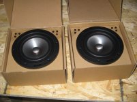
So in short, I want to rip all the guts out of them (amp, speaker cones, etc) and replace them with something newer and better sounding. My problem is I have absolutely no idea where to begin. I've tried looking up guides and tutorials online, but there doesn't seem to be anything I can find for what I specifically want to do. (Speakers AND amp all together in one unit)

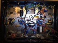
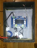
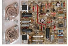
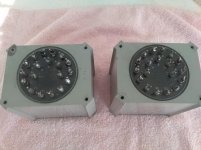
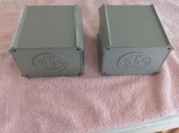
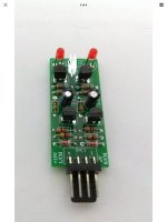
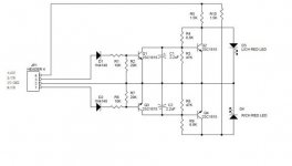
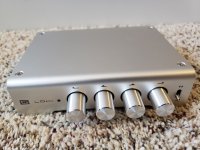
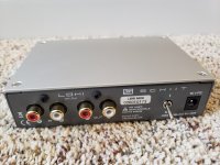
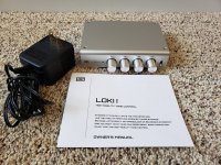
Here are some pictures for what I'm dealing with:

20201203-192328.jpg

20201203-192328 — ImgBB

20201203-184428.jpg

20201203-184428 — ImgBB

20201203-184345.jpg

20201203-184345 — ImgBB

20201203-184343.jpg

20201203-184343 — ImgBB

20201203-184337.jpg

20201203-184337 — ImgBB

(The knobs have already been removed from the pots in these pictures)
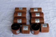
Note the plastic fake dummy tweeter!

It looks like something that should be in theory straightforward: just source equivalent components and swap them out!
However, I just have no idea how to evaluate what is suitable and what's not.

Some specific concerns of mine:
* Make sure the pots and power button line up
* Make sure I can hook up the power LED
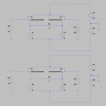
* The amp board needs to accept the correct input and have an output to go to the left speaker
* What sort of power supply do I need?
* Does the amp need special separate outputs for the woofers and the tweeters?

Since this will be hooking up to old computer hardware, I don't really need absolutely top of the line components, but I still want it to sound reasonably good.

So I would really appreciate some help, just getting me on the right path. I don't mind doing my own research, but in this case I just have no idea where to even start!

Yamaha RX-V 550 turn on 1-2 seconds and then turn back off

Hi my friends,

I have a problem with my Yamaha RX-V 550, the amp turn on 1 second and then turn back off.

When I started on the diag mode, I have this message : PS PRT : 000 D

I guess that the problem came from the power supply board or from the big transformer, because when I unplugged the cable that come from the transformer to the front up lever board the amp turn on normally in straight mode.

It's difficult to me to explain my case, I did a little video that explain all that :

YouTube


Any idea ? I'm really lost :/

Thank you so much

Yamaha RX-V2095

Hello All, new to this site, and looking forward to hearing all comments and help I can receive. Not even sure if this post is in the correct section. But here goes. I recently acquired a used Yamaha rx-v2095 receiver at a garage sale for $10 (along with a few other things). Some things I keep, some I resell. Cosmetically it looks ok, but unfortunately I have the same problem others have had. It shuts itself off. At first I was hoping it was from the heat. It has been sitting in my garage since I got it,til I had time to bring it in and take a look at it.

Being the middle of the summer and an unavoidable heat wave, I'm sure it was pretty warm inside. After sitting for only a minute inside my air conditioned home, I plugged it in and turned it on. I heard a click,than a second later another click. looked at the display and saw nothing. I did this a few times with the same results,except that I noticed the display flash for a split second everytime I would turn it on again. I figured it was too hot and let it cool for a few hours in the ac. While trying it again later, no different results. After reading some other users posts, I decided to try some things.

I took off the top and did a visual of the inside. Nothing looked damaged or out of place. While turning the unit on,I would notice a quiet springing sound until the other click. I did attempt to run the self diagnoses. It did show me a message. I had to keep running the diagnosis over and over until I was able to make out the message,since it only displayed for a split second. It said CHK SUM: F300 G / PS PRT : 0%.

I figured before I go crazy taking apart things I don't need to, I would look for suggestions from more experienced experts than myself. I am by no means an expert, but I am fairly capable of testing and repairing all types of things. I can read electrical schematics. My main trade is automotive repair so I am familiar with evolving electronics. Thanks in advance for any suggestions you have.

No DC Offset Adjustment Pots.

I noticed the Sansui A-909 go in and out of protection so I measured the DC offset at the speaker posts. I got 25mv on right channel and 230mv on left channel. Where do I look to fix it? I know opamp NJM4558D has something to do with it, could the opamp be out of spec? The voltage amplifier is not the original STK3082 II going by the schematic.The one in it now is STK3102 II.

Attachments

  • A-909@1.jpg
    A-909@1.jpg
    609.3 KB · Views: 416
  • A-909@2.jpg
    A-909@2.jpg
    615.5 KB · Views: 410

Issues with newly acquired Nakamichi PA-5 Amplifier

You know ho wit goes, you buy a mint, working PA-5 only to find when you receive it that there are 'issues' with it. I did not do my due diligence and purchase a mint PA-5 and CA-5 from someone on Craigslist without listening to them. Bad move. The problems are as follows:

CA-5 - sounds fine after cleaning the pots. I am missing the retainer ring for a knob so it does not 'click' into place when it is placed on the shaft.

PA-5 - here is where my issues are biggest. I was a broadcast engineer but have been out of the field for many years so I am at a bit of a loss on where to start. The amplifier sounds fine when driven with my McCormack and the CA-5 at low-levels of volume or with my iPad driven directly into the PA-5. The problems start when the volume is set over about 9AM on the CA-5 or 10AM on the McCormack and over 50% on the iPad driven directly. There is cracking, static and clipping with the sound reverting to 'thin' to muting to clipping on the RIGHT channel by way of the indicator LED. I am unsure the first step to take in diagnosing the issues. I also have a BUZZ near the power button that is not related to the physical power switch. It was initially not attached as the glue that originally held it had lost the ability to hold. I removed the front panel and after a bit of Gorilla Glue it is structurally solid. It seems the become louder (the buzz) after the amplifier is on longer and increases in level when more drive is provided to the amplifier.

I downloaded the schematics and I will look at it tonight when I put the PA-5 on the bench. I am going to start with cleaning the relay contacts (if they are not sealed) and remove a couple of input capacitors and check them on my Cricket capacitance checker. I am also going to check the FET's for issues short of removing them, although I know it is not ideal.

Any other thoughts? The buzz and clipping? Are they related? What would be the first thing to check?

Thank you in advance,

Darren

DC offset and DC Protection question

I have limited knowledge about electronics and still learning

DC offset is presence of DC at output which is bad if it is too high, after reading many posts anything like 50mv DC should be alright. I understand that a low DC offset is not going to kill any driver.

I was reading about Speaker protection and speaker failures(google), in case full DC voltage is present at output.
-Relays do not provide 100% protection.
-Somewhere it was mentioned to use bipolar cap between Amp O/P and Speaker I/P to block any DC, it was mentioned that a 10000microfarad cap will have not affect on O/P AC signal.

Question
1. Do bipolar caps blocks DC and provides 100% protection from full DC voltage at output?

2. If answer to #2 is Yes, do they have any affect on AC O/P signal from AMP?
3. If answer to #2 is No, then why doesn't everyone uses it to completely block DC from O/P?


My Primary concern/requirement/query is 100% DC Protection due to MOSFET failure or any other reason.

LA4282 without Speaker Protect Relay - Transient/Pop Noise while Switch-ON (Shock-ON)

First happy new year to all.
LA4282 datasheet are available both from Sanyo and OnSemi
LA4282 pdf, LA4282 description, LA4282 datasheets, LA4282 view ::: ALLDATASHEET :::

At the Digital-Piano DP-263 (McCrypt) of my friend - go to
https://asset.conrad.com/media10/ad...l-304303-piano-mc-crypt-dp-263-dark-brown.pdf
occurs a hard popping while switch-on since any weeks (no OCL circuit, i. e. caps in series to the speakers).

The reason was the shorted diode D1 around the mute control unit and the reason for this was again a bad design of the mute control circuit, because a small signal diode for charging a capacitor with 470uF without a serial resistor isn't a good solution - go to the first attached images and there to the first circuit.
One possibility is the use of a diode like 1N5407 (which I have currently realized as an emergency solution).

Because there are no application notes to this IC it is a bit difficult to find a mute control circuit with a sophisticated design.
After study several service manuals I have found this manual of LG television with chassis MC-014A - go to
LG MC-014A CHASIS Service Manual download, schematics, eeprom, repair info for electronics experts

The part of the audio power amp section of the LG chassis MC-014A you will find in the last (third) attachment and the part only for mute control section in the second circuit of first both images.

Here the necessary series resistor was present to limit the charging current for the associated diode. But there are other differences around the base of the transistor.
The MUTE mode in both circuit variants is active, as long as the transistor is in the conducted condition resp. is switched on (while troubleshooting I shorted C-E route of this transistor - therefore I know this exactly).


My questions are follow:
1) What is the task of Dx and the electrolytic capacitor around the base connection of transistor in the first mute control circuit (LG use only a resistor to the positive rail of 9VDC) ?
2) How do I convert the values from the LG-circuit , when I only have 5VDC instead of 9VDC as can be seen in the LG circuit from last attachment (maybe an appropriate modify according to the LG circuit is an approach, which operates better than the introduce of a high-current diode)?

Thank you for replies.

Attachments

  • DSCF7081.jpg
    DSCF7081.jpg
    634.7 KB · Views: 1,092
  • DSCF7083.jpg
    DSCF7083.jpg
    644.9 KB · Views: 543
  • CantabileMcCrypt DP263 LA4282 mod. MUTE-Schaltung.png
    CantabileMcCrypt DP263 LA4282 mod. MUTE-Schaltung.png
    229.1 KB · Views: 1,153

Apogee Stage parts available!

I have a pair of working mid-production-run Apogee Stage speakers PLUS two late-run replacement mid-tweeter ribbons [never used]. I’ve forgotten why Apogee sent me the tweeters, I think they were supposed to be woofer replacements. Been sitting in storage for ~20 years. I pulled them out today to test. The right speaker works perfectly & sounds glorious! Left speaker works well, but bass panel seems quite weak. The raw replacement drivers: one works perfectly, the other has no output at all. [I’ll check for cold/broken solder joints].

Wondering if anybody would be interested in buying any or all of them?
Projects by fanatics, for fanatics
Get answers and advice for everyone wanting to learn the art of audio.
Join the Community
507,765
Members
7,887,482
Messages

Filter

Forum Statistics

Threads
406,178
Messages
7,887,482
Members
507,765
Latest member
aleminx