For creating an electrical model in LTspice, I am confused regarding calculating the resonance Q out of driver measurements. I need this to get the correct Ls and Cs to model the resonances.
I'd like to create accurate models so I can easier calculate starting values for the XO. (To be adjusted of course in the real life speaker, but when ordering the parts it would be nice to be in the ball park).
My example driver:
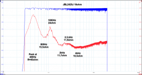
So I have 16ohm variant of the JBL 2425, a HF compression driver. I measured the impedance while they were in the horn I got with them. The lowest resonance I guess is the driver's resonance, while the peak just above 1kHz is due to the horn's cut-off frequency. ?
So to design a crossover I would like to model the drivers. I also want to
reduce or even eliminate the two impedance peaks below the cross over frequency (XO undecided but > 2kHz).
Or is that not a good idea, to insert a network to compensate for the resonance peaks? I think it is because the impedance peaks will mess up my cross over network. If I design the cross over for a 16ohm impedance (11ohm measured, so I will use that value) I will end with certain values for the cap and inductor. But the 24 ohm and 40 ohm hump will shift the cross over points down a bit and the humps should therefore be reduced. Or am I over complicating?
When looking at the measurements the 40ohm peak at 480Hz looks to have a Q of about 2. (3dB bandwidth ca 200Hz, and 480Hz/200Hz=2.4) If trying to simulate an LCR using values of R=40 ohms, Q = 2, and frequency of 480Hz, I get L=26.5mH and C=4.1uF. But simulating this in LTspice gives a much too low peak.
Using a lower Q value the peaks tighten up and look more correct. Isn't this the opposite of what should happen? Higher Q should give higher and sharper resonance peak...?
Using Q=0.25 I get L=3.3mH and C=33uF, and the resoance looks pretty correct. But that was from much trial and error, not understanding anything...
My other question is: When calculating the series LCR to be placed in parallel with the driver, to compensate/eliminate the impedance peaks, do I use the driver's nominal impedance of 16 ohms (11ohms in my case), or do I use the measured impedance at the peaks, 24 and 40 ohms?
I want a flat impedance of 11 ohms over the entire band, so I will start off with R=11ohms, and I suppose that means the L and C needs to be matched to 11ohms, and not the 40ohms measured at the resonance. ?
EDIT: Brain-fart... If I want a flat 11ohms, I need to concider the LCR network will be in parallel with the driver, and the driver itself is ca 11ohms. So my network in parallel must have much higher value for the R... hmm perhaps I will just not have this complicated network, I seem to only confuse myself the more I think about it...
Sorry for confusing questions. How would I go about creating a model out of this measurement?
I'd like to create accurate models so I can easier calculate starting values for the XO. (To be adjusted of course in the real life speaker, but when ordering the parts it would be nice to be in the ball park).
My example driver:
So I have 16ohm variant of the JBL 2425, a HF compression driver. I measured the impedance while they were in the horn I got with them. The lowest resonance I guess is the driver's resonance, while the peak just above 1kHz is due to the horn's cut-off frequency. ?
So to design a crossover I would like to model the drivers. I also want to
reduce or even eliminate the two impedance peaks below the cross over frequency (XO undecided but > 2kHz).
Or is that not a good idea, to insert a network to compensate for the resonance peaks? I think it is because the impedance peaks will mess up my cross over network. If I design the cross over for a 16ohm impedance (11ohm measured, so I will use that value) I will end with certain values for the cap and inductor. But the 24 ohm and 40 ohm hump will shift the cross over points down a bit and the humps should therefore be reduced. Or am I over complicating?
When looking at the measurements the 40ohm peak at 480Hz looks to have a Q of about 2. (3dB bandwidth ca 200Hz, and 480Hz/200Hz=2.4) If trying to simulate an LCR using values of R=40 ohms, Q = 2, and frequency of 480Hz, I get L=26.5mH and C=4.1uF. But simulating this in LTspice gives a much too low peak.
Using a lower Q value the peaks tighten up and look more correct. Isn't this the opposite of what should happen? Higher Q should give higher and sharper resonance peak...?
Using Q=0.25 I get L=3.3mH and C=33uF, and the resoance looks pretty correct. But that was from much trial and error, not understanding anything...
My other question is: When calculating the series LCR to be placed in parallel with the driver, to compensate/eliminate the impedance peaks, do I use the driver's nominal impedance of 16 ohms (11ohms in my case), or do I use the measured impedance at the peaks, 24 and 40 ohms?
I want a flat impedance of 11 ohms over the entire band, so I will start off with R=11ohms, and I suppose that means the L and C needs to be matched to 11ohms, and not the 40ohms measured at the resonance. ?
EDIT: Brain-fart... If I want a flat 11ohms, I need to concider the LCR network will be in parallel with the driver, and the driver itself is ca 11ohms. So my network in parallel must have much higher value for the R... hmm perhaps I will just not have this complicated network, I seem to only confuse myself the more I think about it...
Sorry for confusing questions. How would I go about creating a model out of this measurement?
Attachments
Last edited:
Yes, the compression driver impedance peaks are difficult to navigate when designing a crossover, they are best taken down first.
To save time answering this in-depth question... Why are you using LTspice, is it to remove these peaks? ie. could you measure the impedance and use a crossover simulator or do you need to model the driver instead?
To save time answering this in-depth question... Why are you using LTspice, is it to remove these peaks? ie. could you measure the impedance and use a crossover simulator or do you need to model the driver instead?
Impedance peaks change from horn to horn. Just add the horn drop into the baffle and take Imp measurement. Use that do design the network!
Rob🙂
Rob🙂
Yes, the compression driver impedance peaks are difficult to navigate when designing a crossover, they are best taken down first.
To save time answering this in-depth question... Why are you using LTspice, is it to remove these peaks? ie. could you measure the impedance and use a crossover simulator or do you need to model the driver instead?
Main reasons for LTspice:
1. I use it at work and I am used to it. I also think it can be more accurate since I can add any parasitic I can come up with.
2. its free.
I've been playing around, and finding the L and C is easy enough, and then it's just a matter of playing around with the value for Q untill I get the LTspice to match the measured.
It just buggered me that I have to play around untill I get it, which implies I don't understand what is going on, annoying me a bit.
Any cross over sims you recommend?
Finding a best fit is just par for the course sometimes. Even when it isn't there are times when it is simpler in the long run. The result is still accurate.
There are ways to test the CD and model it, there is some discussion on this site.. but the simplest is to measure the impedance. A good thing about using a crossover simulator is it will do an analysis of the circuit's effect straight on the measured plot but if you can do this with LTspice, then no problem.
XSim free crossover designer