You are using an out of date browser. It may not display this or other websites correctly.
You should upgrade or use an alternative browser.
You should upgrade or use an alternative browser.
Filters
Show only:
When SITs sit in my drawer
Hi guys, I am in DIY audio for some time and realised that what works best to me is minimalism. In my case: I steal I2S signal from modified Squeezebox Dual and provide it to the Soren DAC connected directly to power amp: Firstwatt F5, Harman Kardon 402 power amp or EL84 (as a pentode) with 12AU7 as a driver at a few mA with no global NFB and no cathode resistor just 8-9V negative voltage on the gate, volume is regulated in the digital domain. It's great, there is magic, listen to Macy Gray, album Stripped at 24bits and 96kHz and it sounds wonderful, I am really happy with it… but you know, there is always possibility that maybe… there is something more magical and it’s not the end of the journey 😕
I am lucky enough - not that I'm bragging - to own two matched pairs of Semisouth JFETs that I purchased a few years ago. Initially I was planning to build FirstWatt F6 - I have all the parts including transformers… but… I am happy with F5 and I don’t think that F6 will make a huge difference.
However recently I have read about F1J and F2J and this is completely new concept to me. I own a pair of Markaudio Alpair 12P so happy to build horns but not sure if these drivers is good match for these unusual amplifiers…
Guys, any magical experience with F1j or F2J? If so what speakers are you using with them? Or maybe you have other idea how I could use these two pairs of JFETs.
P.S. I need to mention that I have also some 2sk82 and 2sj28 that are still waiting to be used in some exciting project 🙂
cheers
Kicker CXA360.4
Having a little trouble with this Kicker. Had one output transistor, D718. I have replaced it and didn't find not other components shorted in the channel.
When I apply power the amp cycles in and out of protect. The outputs are out of the amp now, and it is still doing it.
When I apply power the amp cycles in and out of protect. The outputs are out of the amp now, and it is still doing it.
Reverse freq/gain/qfactor from biquad coefficients
For a DSP board I am working on a way to not only upload settings, but also download them from the board.
I could in theory send extra data along, but since the board already gets the a0/a1/a2/b0/b1/b2 coefficients, it would be nice to reverse engineer the filter type, frequency and qfactor from that.
For the conversion from filter specs to coefficients I use the RBJ cookbook formulas. Is there some way to reverse these formulas or would that be mathematically impossible?
DIY edge-driven Ultrasonic RCM from Lego
- By Baserolokus
- Analogue Source
- 2 Replies
While busy building a edge-driven UCRM from cardboard and 3D-printer parts I had to wait for my 0,5 RPM 12v motor and I thought why not give it a go with some Lego. We have 3 boys hopping around so piles and piles available including loads of technic lego and a 9v motor.
Loading 2, or maybe 3 records on a spindle and hang that on a motor that then has to lower itself in the tank seemed a bit of a hassle to me.
Build was pretty straight forward as you can see. The basic construction I came up with fits my tank perfectly. This basic form will probably fits most tanks when tweaked a little and can be removed very easy. In the beginning the option of glueing the Lego blocks crossed my mind but it seems that is not needed. Still have to wash my first record though. Building a 0,5 micron automatic pump system on the side and have to finish that first.
Feel free to share this wherever you want and good luck building your own!
DIY build your own edge-driven Ultrasonic Record Cleaner Machine from Lego - YouTube
Denon DRA-300 Dead Left Channel
- By 22asd
- Solid State
- 47 Replies
I recently found our old family receiver and put it in my room only to find out that the left channel was not working.
I opened it up to find that the left channel fuse was blown. I could not seem to find a match for that fuse type, but I found some PICO fuses in China that matched the 4A 125V.
After soldering it to the bottom joints of the fuse holder and regaining the connection, the channel still does not work, maybe something further upstream is damaged?
I have 0 experience with receivers or audio and could not find a schematic for the DRA-300. Just hoping someone might have a suggestion or schematic. I got a scope, meter etc
New guy need some help with old speakers
Posted this under full range which might be the wrong sub forum, so re-posting here.
Hi, looking for some advice. I broke the terminal on my Vifa d25AG35 tweeter and am looking at options for replacing or re configuring my speakers.
My system consists of 2 rather old custom made transmission line units which originally came with KEF b110 woofer and T27 Tweeter. At some point they were rebuilt using a VIFA p13 mid-woofer and the above mentioned D25 (which is no longer available). I also have a pair of 10 inch sub-woofer which I am Bi-amping with a 24db/octive electronic crossover at 90hz (I can also choose 120hz). I’m using a pair of Adcom 5400 amplifiers rated at 125W per channel to drive the speakers.
Looking for options
Should I try and replace my current drivers?
Should I try full range with something like the Markaudio 7MS and eliminating the current passive 2 way crossover.
Should I consider a single drive open baffle design
I’d appreciate some feedback with options, pros and cons, etc.
Thanks, appreciate any help. If you need more info let me know.
Linkwitz Lab tone burst test CD
- By jan.didden
- Swap Meet
- 0 Replies
I bought the Linkwitz Lab tone burst test CD for a project many years ago. I don't really use it anymore so looking for a loving home. € 25 including worldwide shipping.
The track list explains it all.
Jan
The track list explains it all.
Jan
Attachments
SA01 Spectrum Analyzer software - development in progess...
- By s3tup
- Software Tools
- 44 Replies
UPD: Version available
Download SA01 Spectrum Analyzer — XDXD Solutions
Hi all! I'm in the middle of development of a spectrum analyzer software, and would like to share my insights as well as hear your ideas about it 🙂
Yes, it will cost money. Circa $50 for community and $300 for professional editions, without any difference whatsoever between the versions (Pro is for >~10 employees company). I'm unemployed for the past year and working full-time on this project.
If i've misplaced the thread, please move it to the "vendors" section. The software is still in development and i don't have any due date...
This is how it looks right now:
I'm trying to cover all the useful audio measurement techniques as well as implement more generic processings - to give some freedom to the end user regarding the workflow. Works with sound cards (WASAPI/ASIO/MME). Might support other hardware in future. Windows only 🙁 I'm already too deep in windows/hardware optimizations/quirks, can't make them cross-platform.
It's about being a tool rather than "following strict orders", mimicking hardware-based analyzers.
Touch, eyes and user-friendly, without much handicapping nor over-complicated settings, everything is within reach of 2 clicks to modify and ZERO CLICKS to see 🙂
So far i've got it running
- 16M FFTs at 11FPS (i7 4790k), or like 0.5-1FPS on really weak Atom tablet. 20-25FPS 65K FFT on the same tablet.
- Phosphor/persistence display + display of "all FFT points"
- Various math and averaging options, including synchronous averaging that actually works without sync signal (20dB noise reduction in couple of seconds), cross-correlation, 2-channel transfer functions and so on
- "Very-Dynamic-Sample Rate Converter" - both for the basic stuff (SRC, decimation) as well as neat PLL-locking to measured signal's carrier frequency and reducing it's phase noise/wander, as well as syncing it to "bin centre" frequency for window-less scalloping-less or consistent really-long-FFT measurements.
- Phase Noise measurement
- Support of "notch/filtered" THD, IMD measurements by performing 2-channel FFT and then combining responses together (most consistent way of doing such thing)
- "Noise floor extension"
and many more 🙂
Currently i'm working on implementing on-the-fly switchable measurement setups in "chrome tabs" way. It's quite possible you won't have to stop the measurement flow whilst switching between tabs... quite a challenge as i need to switch ALL of the measurement settings altogether without any hiccup.
More on Software Spectrum Analyzer — XDXD Solutions 🙂
Attachments
AE-Europe transformer Set KT88 Monobill,anodized chassis parts, tubes, cables, ... .
I´m selling a complete AE-Europe set for Triodedick`s Monobill Classic monos.
The power trannies are potted.
Supplied within this sale are all needed tubes likes unused and factory matched Electro Harmonix KT88 and nos prestage valves.
Furthermore there´s a box with a lot of smaller parts like selected Mundorf supreme caps, big JJ elcos, PRP resistors, silver plated teflon wire, speaker binding posts, tube sockets and fixing material.
Chassis parts will also be included. They are made of 5 and 10 mm aluminum, are perfectly brushed, threaded on their back and anodized.
After buildup they`ll look like the phonopre in the picture (not included). Its parts were made in the same run.
All things are in like new condition. Just one pottet tranformer has a small scratch which won´t be visible after mounting. Nothing serious.
Asking 800 Euros plus transport. Local pickup preferred.
Place: 52525 Heinsberg, Germany.
An externally hosted image should be here but it was not working when we last tested it.
FS: Scan Speak Revelator and Illuminator tweeter faceplates
I have some spare faceplates from 6600, 7100 and 7000 tweeters, they are new, just were removed from tweeters as I needed to fit WG. I will not use them anymore, and someone might appreciate new faceplates.
50euro/pair. EU.
petr.kocourek@gmail.com
50euro/pair. EU.
petr.kocourek@gmail.com
Attachments

Silentblock for audiovisual systems
I would like to install a 22" touch control screen in a van (audiovisual source with barobone)
how to prevent display malfunction due to vibrations, speed bump ?
what products do you choose to isolate system ?
how to prevent display malfunction due to vibrations, speed bump ?
what products do you choose to isolate system ?
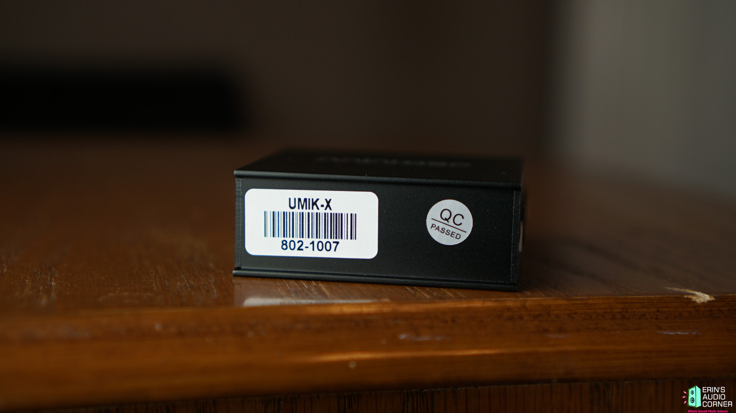
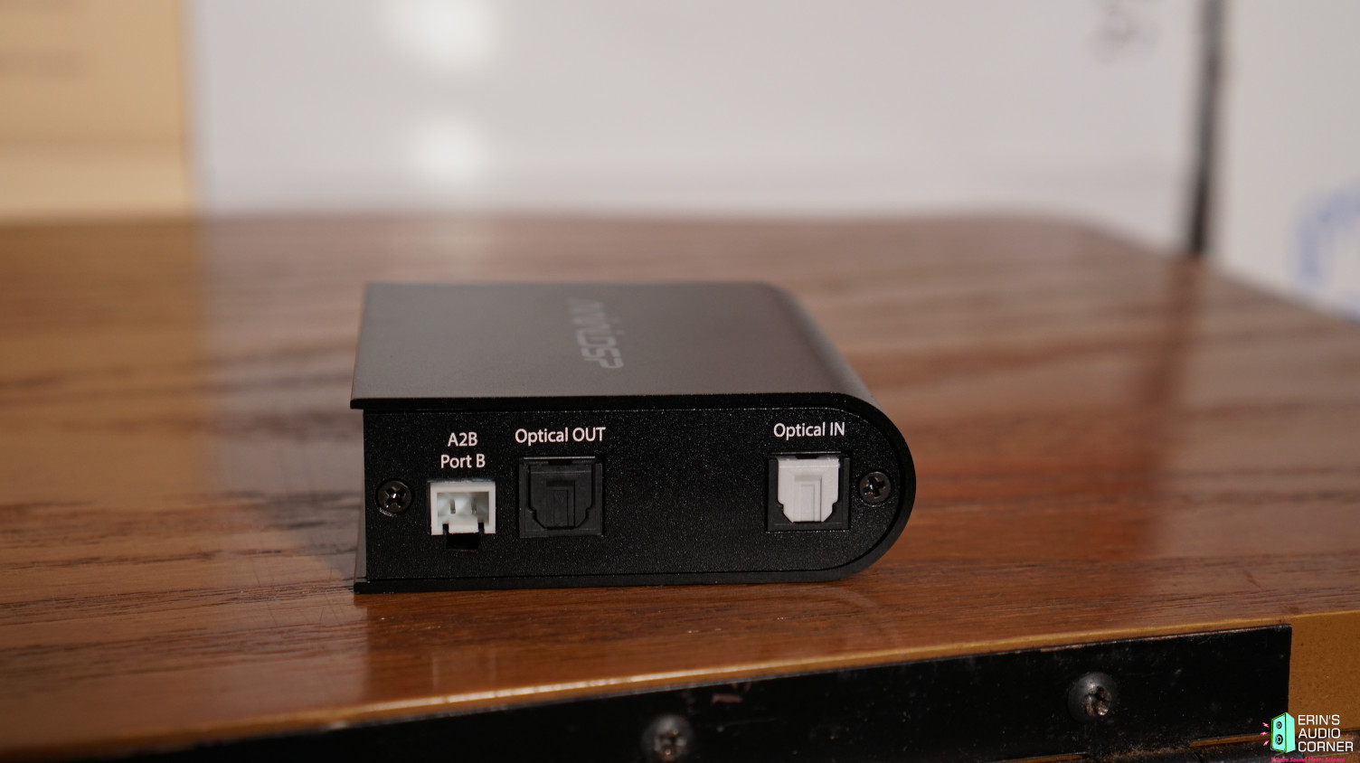
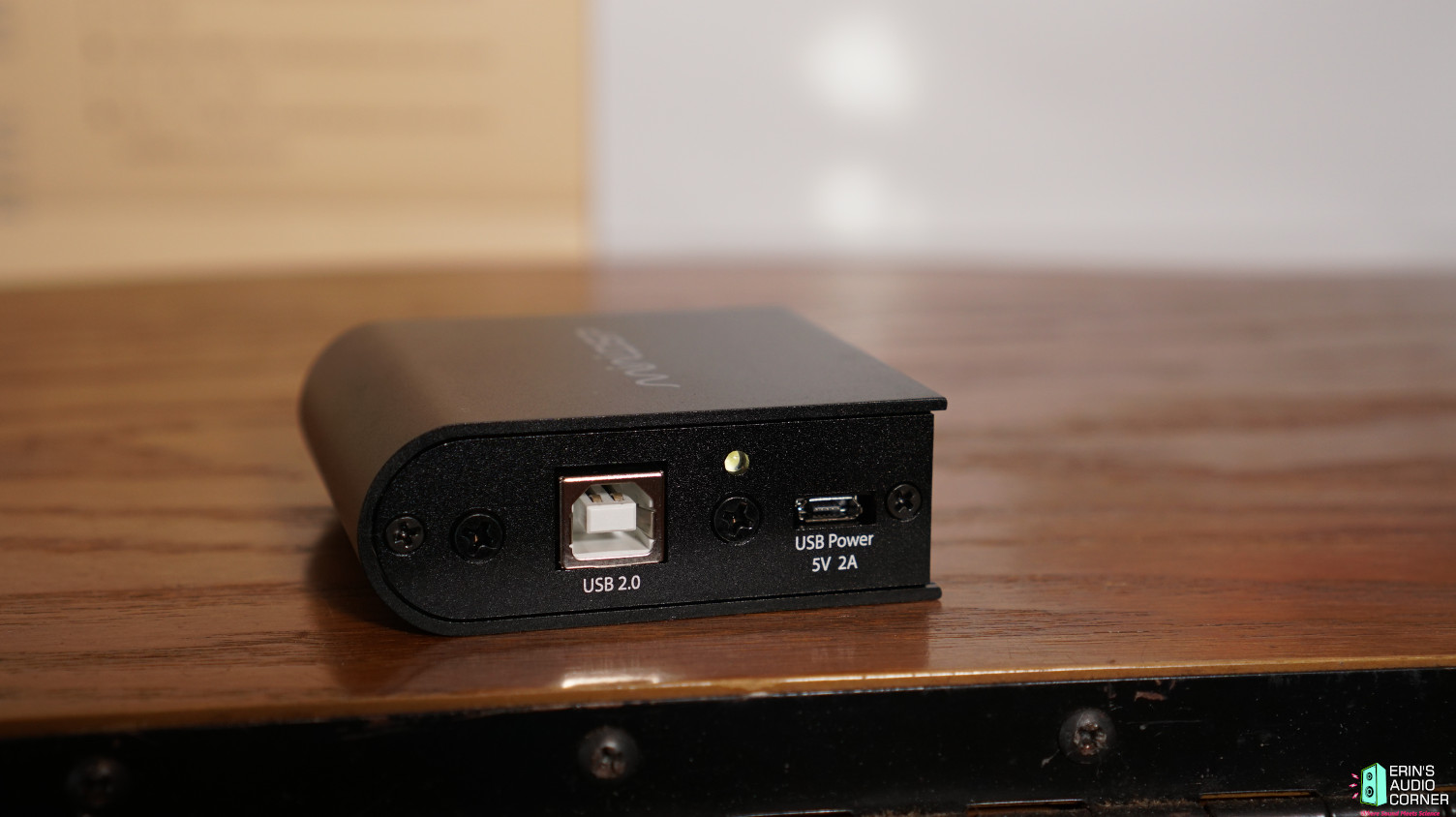
MiniDSP UMIK-X Microphone Array
- By bikinpunk
- Room Acoustics & Mods
- 4 Replies
I received (2) pair of MiniDSP's new UMIK-X for review yesterday. This recently hit the market so for those who aren't up to speed on things, the UMIK-X is an arrayed microphone setup that is designed to provide an averaged response across its four corners.
This would make taking spatial averages or measuring in various seats a more reproducible, accurate and time-saving task compared to the standard moving mic method (MMM) or moving mic average (MMA). There are many uses for this kind of thing.
Some quick notes:
The cost is $550 for a pair of microphone arrays, a USB adapter and a license to REW Pro ($100 value; necessary to use REW with an array microphone). Each pair means you get (2) arrays. Each array has (4) microphones; one at each corner of the array. So each pair then comes with (8) total arrayed microphones. You also get (2) stands and extension poles to set them up however you desire. This means you can attach the pair together on a single fixture as I have shown below OR you can place each individual mic array at different locations. Ideal for measuring different locations such as different seats in a car, multiple seats in your home theater, or possibly even used in lieu of the "subwoofer crawl" (I'm going to test this idea). Or, you can simply pair multiples to provide a more distributed array in a single seated position. Or, you can simply pair multiples to provide a more distributed array in a single seated position. You can also just use the array without a stand, in which case it takes up less than 7x7 inches and is paper thin. As I said, there are many uses for something like this.
Four arrays can be combined for a total price of $750, netting you 16-channels of recording.
Not sure when I'll get the proper review completed but hopefully it will be soon. Make sure to subscribe to my YouTube page and click the notifications button because I'll be doing a YouTube video review rather than typing one up (easier to demo). Link: Erin's Audio Corner - YouTube
Until then, you can read more about the UMIK-X here: UMIK-X - USB audio Multichannel Measurement microphone array set
Some photos:
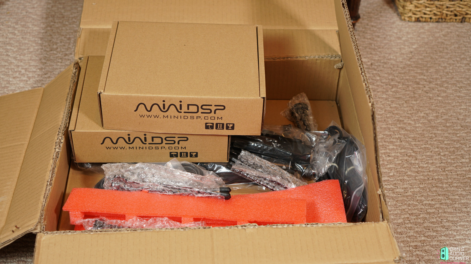
Below is a photo of the 4 arrays I received, individually wrapped, with one of the arrays out of the packaging. You can see the single array here is quite small (6.25in x 7in) and practically paper thin.
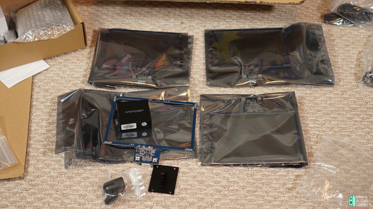
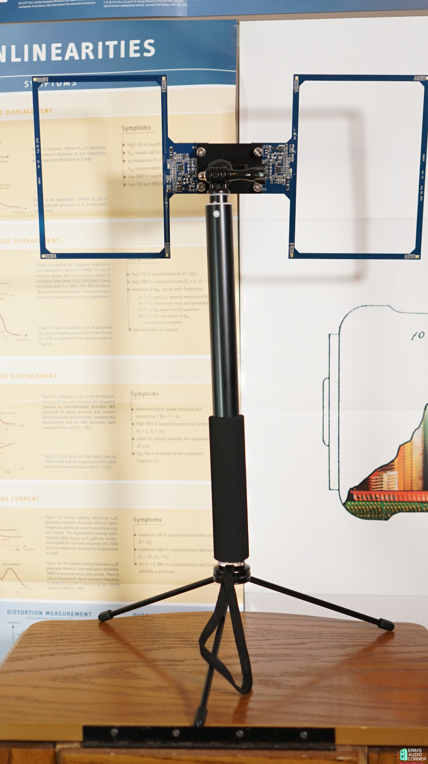
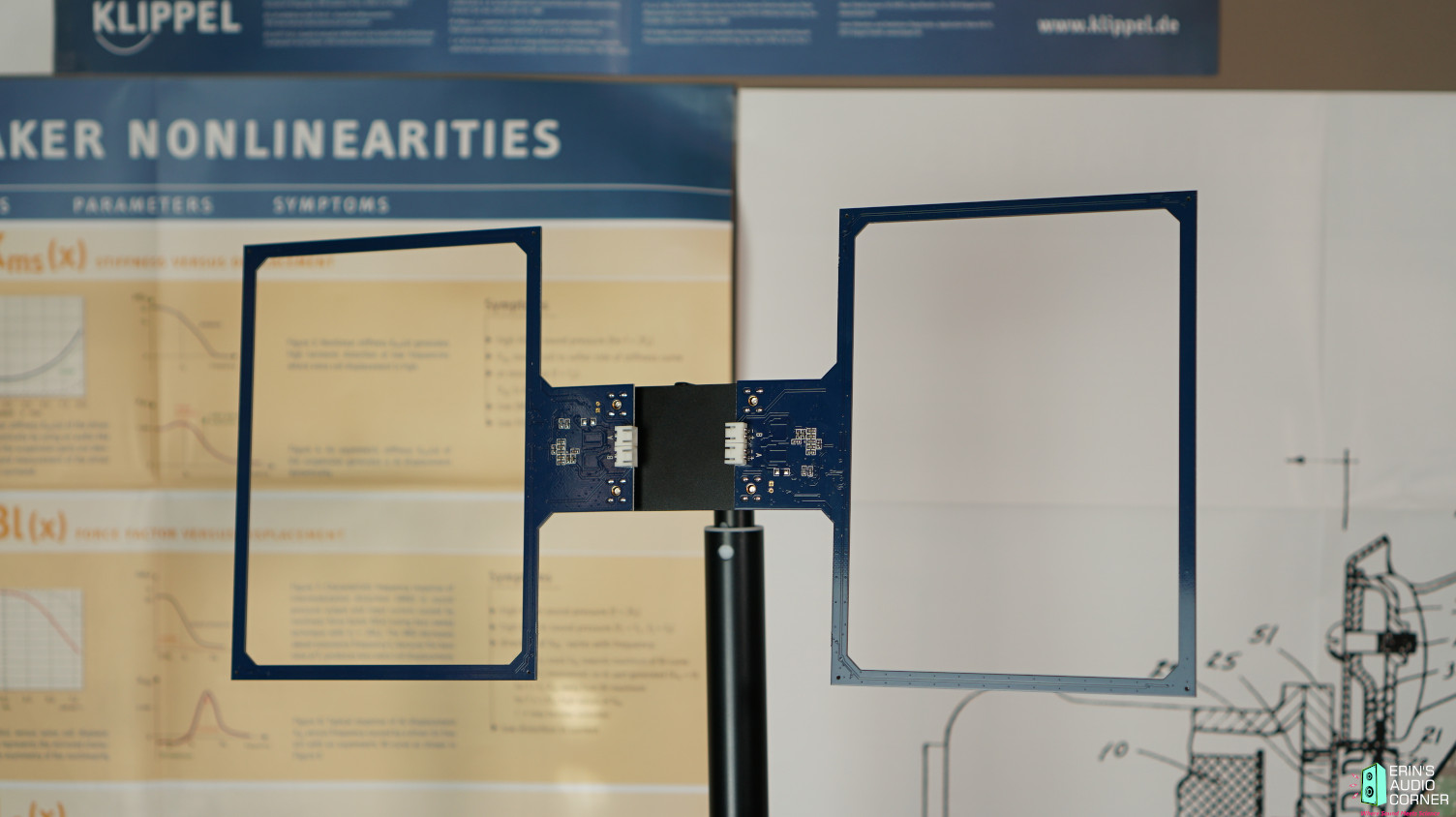
Two arrays connected together. Again, these can be configured in pairs or you can mount a single array to the mic holder. Depends on what you're trying to measure.
Here are some photos of the USB converter box, where the mic arrays connect and are then sent via USB to your computer.
This would make taking spatial averages or measuring in various seats a more reproducible, accurate and time-saving task compared to the standard moving mic method (MMM) or moving mic average (MMA). There are many uses for this kind of thing.
Some quick notes:
The cost is $550 for a pair of microphone arrays, a USB adapter and a license to REW Pro ($100 value; necessary to use REW with an array microphone). Each pair means you get (2) arrays. Each array has (4) microphones; one at each corner of the array. So each pair then comes with (8) total arrayed microphones. You also get (2) stands and extension poles to set them up however you desire. This means you can attach the pair together on a single fixture as I have shown below OR you can place each individual mic array at different locations. Ideal for measuring different locations such as different seats in a car, multiple seats in your home theater, or possibly even used in lieu of the "subwoofer crawl" (I'm going to test this idea). Or, you can simply pair multiples to provide a more distributed array in a single seated position. Or, you can simply pair multiples to provide a more distributed array in a single seated position. You can also just use the array without a stand, in which case it takes up less than 7x7 inches and is paper thin. As I said, there are many uses for something like this.
Four arrays can be combined for a total price of $750, netting you 16-channels of recording.
Not sure when I'll get the proper review completed but hopefully it will be soon. Make sure to subscribe to my YouTube page and click the notifications button because I'll be doing a YouTube video review rather than typing one up (easier to demo). Link: Erin's Audio Corner - YouTube
Until then, you can read more about the UMIK-X here: UMIK-X - USB audio Multichannel Measurement microphone array set
Some photos:
Below is a photo of the 4 arrays I received, individually wrapped, with one of the arrays out of the packaging. You can see the single array here is quite small (6.25in x 7in) and practically paper thin.
Two arrays connected together. Again, these can be configured in pairs or you can mount a single array to the mic holder. Depends on what you're trying to measure.
Here are some photos of the USB converter box, where the mic arrays connect and are then sent via USB to your computer.
Parafeed headphone Transformers
- By adamus
- Tubes / Valves
- 0 Replies
Morning all
I currently have the small edcor pcb transformers which i got super cheap a few years ago.
Really interested to hear if people have had similar, and upgraded to sowter or lundahl, or electra-P etc... AND HEARD A DIFFERENCE IN QUALITY.
Thoughts very welcome, i have £250 needing to be spent (tax rebate, its the law you have to spend it on superfluous things!)
Box in a box speaker
- By cracked case
- Multi-Way
- 6 Replies
I just thought that I'd share an idea for reducing the transmission of vibration from the driver to the enclosure, comments welcome. 1 is the bass enclosure, ( with aperiodic loading ), 2 is the tweeter box and 3 are the spring things that hold them against the front baffle ( with foam gaskets between ) . 


The " tweeter " is a full range GAOHOU 52mm 4Ohm driver that has an output that rises above 2,000 Hz, so making the crossover easier. The bass driver is a cheap 6" paper from Maplin (RIP ).
The " tweeter " is a full range GAOHOU 52mm 4Ohm driver that has an output that rises above 2,000 Hz, so making the crossover easier. The bass driver is a cheap 6" paper from Maplin (RIP ).
Triode connected E180F/6688
- By vetmedrobert
- Tubes / Valves
- 14 Replies
The pinout for this is nearly identical to a triode strapped 6E6P-DR. With the latter pin 8 goes to ground. The E180F pin 8 has a screen and g3, does it need to connect to the cathode pin or is it ok to connect to ground? Thanks for your help🙂
Tubes for sale
- By Yuriy62
- Vendor's Bazaar
- 1 Replies
Sale:
6P14P-EV - 2000 pcs. for $10 ea.
6P14P-ER - 400 pcs. for $10 ea.
6N23P-EV - 200 pcs. for $20 ea.
6S45P-E - 300 pcs. for $10 ea.
6P3S-E - 800 pcs. for $7 ea.
6C33C-B - 2000 pcs. for $20 ea.
6P14P-EV - 2000 pcs. for $10 ea.
6P14P-ER - 400 pcs. for $10 ea.
6N23P-EV - 200 pcs. for $20 ea.
6S45P-E - 300 pcs. for $10 ea.
6P3S-E - 800 pcs. for $7 ea.
6C33C-B - 2000 pcs. for $20 ea.
Trying to fix a Class D Alpine
Hello, I'm looking for any experienced advice on this thing. It is an MRV-F300 with a weak channel.
Its volume it about half of it's other pair and with a lot less bass. I can't quite tell the highs for sure, but it is without a doubt overall weaker. Nearly all of my searching on amp repair is power related, but on this I don't know if power can cause these symptoms and I can't find a service manual 🙁
Its volume it about half of it's other pair and with a lot less bass. I can't quite tell the highs for sure, but it is without a doubt overall weaker. Nearly all of my searching on amp repair is power related, but on this I don't know if power can cause these symptoms and I can't find a service manual 🙁
Jean Hiraga Altec A5 Crossover modification
Hello All.
I recently built this Jean Hiraga crossover for the Altec A5 in order to combine a 511B with a Renkus-Heinz SSD-1800-8 compression driver and a Peavey FH1 with an Eminence Kappa 15C. When I started my build the specs that I looked at for the original LF cabinet that came with the Altec VOTT A5 indicated that it would have a sensitivity close to what the FH-1 with a 15C would have. Apparently, I was mistaken, as the specs for Altecs 828 cabinet show it to be substantially less sensitive than the FH-1 with a 15C. Basically the FH-1 combo is 6-7 DB more sensitive than an 828 cab. I realized almost immediately that there was an issue, as there was obviously too much bass in the output.
I need to attenuate the bass by around 6-7 DB. I added an L-Pad on the output of the Hiraga, as per Pete Riggle's modification of the Hiraga crossover, in order to control the treble, but there is not enough treble even with the L-Pad set to let all the power through to the HF section. Looking at the schematic, there doesn't appear to be any mods that I can make to it that will increase the overall treble level while still maintaining the equalization that the horn/cd combo requires. Am I correct in thinking that my only solution is to add an additional L-Pad to the LF section? Should I move the existing L-Pad to the woofer section, as it is useless on the HF section? Or am I missing something? Any advice would be greatly appreciated.
This is the link for the Hiraga crossover as modified by Pete Riggle....
Altec A7 Voice Of Theatre Speakers - Vertical Tracking Angle on the Fly (VTAF)
Attachments
Emotiva A-700
Emotiva A-700 Seven Channel Power Amplifier
Great condition. No longer needed as I am liquidating my multichannel setup and going back to basic two channel stereo.
Power Output with two channels driven is 110 watts RMS / channel; 20 Hz - 20 kHz; THD < 0.1%; into 8 Ohms
If interested I'll be glad to send photos.
Asking $350 plus shipping.
Great condition. No longer needed as I am liquidating my multichannel setup and going back to basic two channel stereo.
Power Output with two channels driven is 110 watts RMS / channel; 20 Hz - 20 kHz; THD < 0.1%; into 8 Ohms
If interested I'll be glad to send photos.
Asking $350 plus shipping.
Need help with 6E5P UL bias point.
- By Tjj226
- Tubes / Valves
- 4 Replies
Hello everyone. I hope everyone is still doing well during these times.
I have a couple edcor 7.6K UL push pull transformers that I would like to turn into a small amplifier.
I am looking at using a single stage 6E5P push pull amplifier and I would like to give UL a shot with these tubes to see what sort of power I can pull out.
The problem is that I can't find any UL curves for this tube, so I can't figure out what the bias point should be.
If any of you could point me in the right direction, or if you guys think UL with this tube might be a waste of time, please let me know.
eBay parts suck
Don’t order parts on eBay, I’m convinced they’re all counterfeit. You can see the dies on these supposedly genuine transistors aren’t even 1/4th the size of the originals, and though the amplifier seemed to work OK they blew and torched a receiver I repaired at only modest volume levels. So learn from my mistakes, even if you don’t think it matters, it really does- even at low power levels.
Attachments
WTB US AMPS 500a
I am looking for a us amps 500a . I had one back in the day and I am doing a new build and trying to find one . Let me know what you got
Philips tda1305 (hybrid multi-bit/bitstream DAC with interpolation)
- By 1z2a3y
- Digital Line Level
- 37 Replies
Seems as if the mid-1990s-designed Philips tda-1305 has gained a cult following in the Chinese diy community, and maybe certain UK high-end manufs, too.
Current AMR cd player that uses tda 1305:
CD-777 SE Compact Disk Processor by AMR Audio
Legacy AMR cd player (used tda 1541a; AMR later switched to tda1305):
CD-77 Compact Disk Processor by AMR Audio
Legacy Naim CD 3.5 CD player from 1998:
Naim CD 3.5 CD player | Stereophile.com
Various low-cost TDA1305 Chinese kits on Ali and eBay including this USD $31 2x TDA1305 device:
Dual TDA1305 DAC chip + CS8412 Digital reception + CM108 USB Fever Class HIFI DAC Decoder board With usb fiber coaxial input|dac decoder board|dac decoderhifi dac - AliExpress
....and this USD $30 TDA1315H+TDA1305T device on eBay:
TDA1315H+TDA1305T Decoders Fiber Coaxial To AnalogAudio Signal DAC ZJ-64 | eBay
And indiv. 1305 chips are readily avail and dirt cheap on eBay and Ali.
tda1305 datasheet:
http://www.acoustica.org.uk/t/naim/data/TDA1305.PDF
ID this mystery twin triode?
- By deafen
- Tubes / Valves
- 21 Replies
This Magnavox-branded twin triode was pulled from a 1960's console. The power amp is an 8601-10, but this was pulled from the tuner/phono section. I can't find anything etched on it. The silkscreening says "MAGNAVOX", "Made In U.S.A.", and some numbers and letters I'm having a hard time reading. I don't really care about brand, but I'd like to know what part it is!
The plate structure is unusually "bulbous", and the plate tabs above the top mica are pretty distinctive. Any guesses as to what it might be?

The plate structure is unusually "bulbous", and the plate tabs above the top mica are pretty distinctive. Any guesses as to what it might be?
pre-amp wiring error question
- By N3HGB
- Tubes / Valves
- 6 Replies
This schematic makes no sense, it seems like grounding one end of a wire directly and the other end through a resistor and capacitor is useless.
Attachments

how to connect an EL34 pentode into a triode and 100ohm resistor between plate and g2
- By jarthel
- Tubes / Valves
- 17 Replies
here's the Mullard datasheet: http://www.mif.pg.gda.pl/homepages/frank/sheets/129/e/EL34.pdf
here's the Phillips datasheet: http://www.mif.pg.gda.pl/homepages/frank/sheets/030/e/EL34.pdf
=================
1. According to Philips (top of page 7), I need to connect grid2 to plate and I'll get a triode.
BUT according to mullard (page3), to get a triode connection, it's grid2 to plate and grid3 to cathode.
so which is right? It is possible as well that I misread the datasheet.
ps. I've seen replies were people have recommended the Mullard way but Philips must know something if they are recommending it differently.
2. I've seen replies where people have suggested a 100ohm resistor between plate and grid2. But I was looking at the mullard and philips datasheets and it seems I only need a piece of wire to connect the two pins.
what is the purpose of the 100ohm resistor?
Thank you for the help
best reflex box: vb=vas, f3-fb=fs ?
- By jenoux
- Subwoofers
- 14 Replies
I'm simulating the box of the FaitalPro 18xl1600,
it will be used in a 4-way hifi system from 30 to 100hz
this driver has a 176 liter vas and a 32hz fs.
The best result that is
vb = 190 liters
fb = 32hz
f3 = 32.5 hz
is it possible to have the VB greater than or equal to the VAS?
it will be used in a 4-way hifi system from 30 to 100hz
this driver has a 176 liter vas and a 32hz fs.
The best result that is
vb = 190 liters
fb = 32hz
f3 = 32.5 hz
is it possible to have the VB greater than or equal to the VAS?
Valve FM receiver
- By baudouin0
- Tubes / Valves
- 63 Replies
OK so I thought I'd build something different from an amp. I had given up with getting the coils for the IF, but then came across this kit.
Vintage Valve Tube FM Radio DIY Kit Stereo Receiver Frequency Modulation Board | eBay
Its from China and probably a copy of something. However its comes with newly wound double tuned IF coils and a double sided PCB of very good quality with ground floods on both sides. The tuning cap is a reused unit but I would like to change the design to synthesised varicap tuning.
There's a schematic here:
IWISTAO Tube FM Stereo Radio Tuner Finished PCBA Preamplifier Version No Including Power Transformer HIFI Audio 110V/220V DIY|hifi wire|transformer currenthifi component - AliExpress
I don't have consent to put in the one I have.
I have test equipment to get the thing up and running.

Interview with Lars Risbo of PURIFI Audio
- By bikinpunk
- The Lounge
- 1 Replies
Wasn't sure where else to put this so hopefully this works...
I recently had Lars Risbo of PURIFI Audio on my channel to chat. To those of you who missed it, a link is below. Lars provided an overview of how drive units work, insight in to what makes PURIFI drivers so exceptional, and an exclusive look in to the hardware and software used in their R&D work.
I know I speak not only for myself but the community as well when I say "thank you" again to Lars and the rest of the PURIFI team who helped facilitate this and offer some insight of their own via the chat. Maybe we can do this again in the future.
Live with PURIFI Co-Founder Lars Risbo! - YouTube
The LM1875 for best
I decided to design the LM1875 for its best. First I will study the character in detail , sort out the problems to resolve and bring solutions to get highest quality possible. It can be paralleled and bridged, it can be composite or not.
Hayk
Hayk
mini-aleph versus aleph-3
Has someone experimented with the mini-aleph side-to-side with a pass aleph-3?
I wonder how the differences in sound quality can be described between these 2 same designs using one pair instead of two pairs of output transistors.
I guess there will be some extra smearing in the sound when using pairs parallel. But otherwise: why should super amps using 24 pairs or more in parallel sound so good?
Best is:
* using same components quality.
* using same idle current and voltages.
* judge within same power envelope (say first 10 watts)
Or in other words: when no more power than 10 Watts per channel is required (easy 8 ohm load with high sensitivity) would the mini-aleph always be a better option, not only theoretically but also tested in practice?
>>> 6n23p Tube: Differences and types... <<<
- By TasoTaso
- Analog Line Level
- 0 Replies
HI, good evening,
I should buy a quartet of these tubes, I read a little here and there on the net to clarify the versions.
Discarding (???) the Reflectors that all those who have tried them between the various versions / brands / place of construction say they sound a little "solid state", I would be directed to those produced in Voskhod, therefore with the "rocket" logo.
Since there are several vintages and different getters, EVs, etc ... is it not by chance that someone among you has experience on this and can advise me by making a sort of "lineup"?
I also see that sellers mention "gold grid" or "silver shield" .....
Thanks! 😀
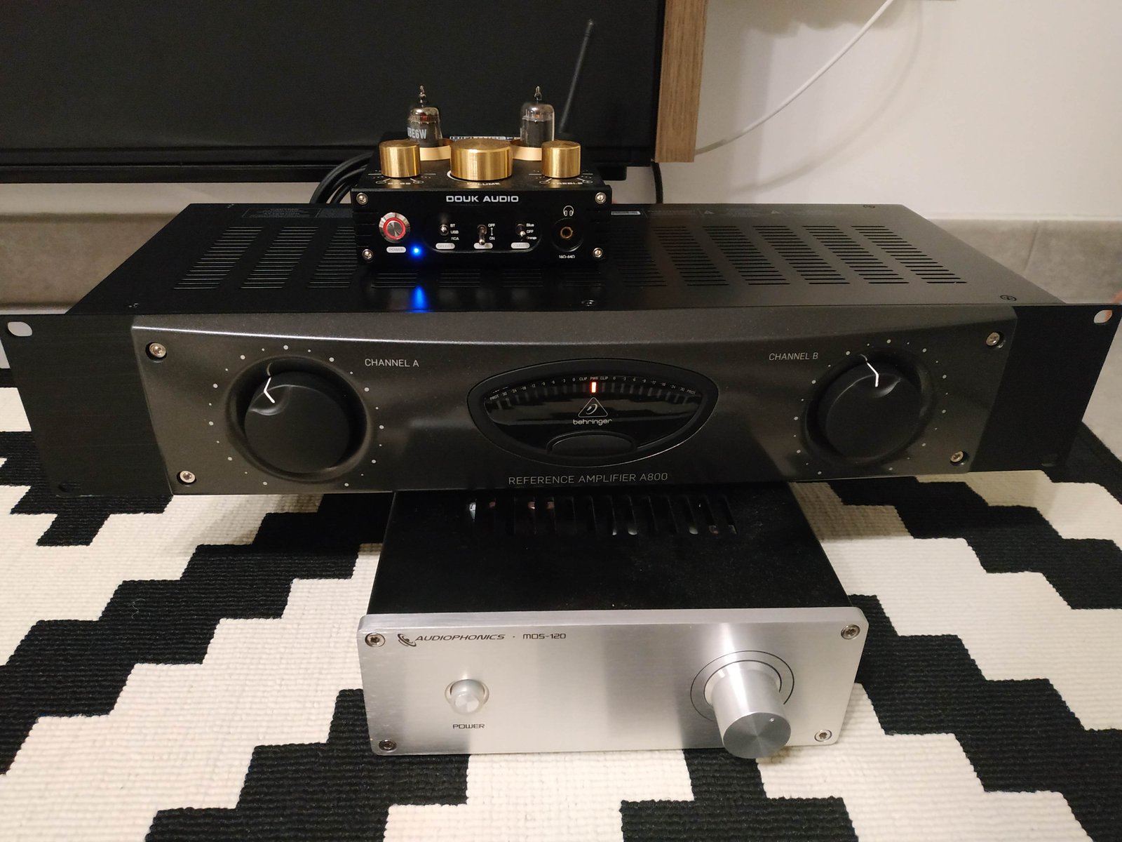
Berihnger A800 full review, pictures INSIDE )
Hi amigos,
This is probably the first shots of the Berihinger A800 Class D amplifier.
I heard lots of great reviews about this Amp and I tried to ask to Berihinger customer serice some info. about the audio chip : they were not allowed to share those technical informations. I also asked to Thomann in Germany but the same... this is like a secret )
So, I started the adventure and decided to share a little review.
Keep in mind that this review is based on my discerning musician ears. I have been playing drums for many years now and my father is classical guitarist as well. So that I can compare, I specify that I have several amps. (High end AB amp, TPA3255 Amp Purepath, TK2050 Tripath)
My equipments :
- Audiophile Audio Player
- Tube DK TP01 Preamp + Sylvania EBE6W NOS Tubes made in the USA
- HD Audio 24 Bit Playlist : Jazz / World Music / Voices Female + Male
- The Preamp is connected via XLR balanced inputs
- Hi ends Floors Speakers 3 way / 93DB @ 8 ohms handmade in France
Berihinger A800 spec :
Output circuit type Class-D
Circuit protection Short circuit current, DC fault, AC fuse, thermal cut
Distortion (4 Ω @ 150 W @ 1 kHz) <0.08 %
Damping factor >160 @ 8 Ω
Frequency response @ -10 dB below rated output power 20 Hz to 20 kHz, +0/-1 dB
Frequency response @ -3 dB 10 Hz to 30 kHz
Signal-to-noise >100 dB (A weighted, 20 Hz to 20 kHz)
Voltage gain @ level control max Balanced: 30 dB / RCA: 41 dB
Input sensitivity @ level control max XLR: +4 dBu / RCA: -10 dBV
Sound Stage :
Compared to my AB high end amplifier, I would say that the A800 has clinical or even a surgical sound, extremely well balanced with a formidable precision in the low ends. This is pretty typical with Class D amps but I have to admit that the balance between all the frequencies is quite exceptional ! Audio image is really great (this depends also on recordings and tubes)
Musicality :
The musicality is a little to the detriment of the accuracy of this class D Amp. Question of taste probably.... With the A800 you will really hear some suprising details (sliding guitar strings, articulations on the snare etc)... It is as accurate as the TPA3255 maybe better to my ears but a little less warm than my AB amp.
Dynnamics :
Excellent ! The music really live : the amp has a lot power. Listening is not tiring really amazing. The range of how gently or strongly are played the instruments is clearly noticeable.
Noise / Signal :
AMAZING ! absolutely dead silence between songs even with my Volume control @70%.
Conclusion :
For this price, I think it is impossible to Out perform this Class D amp.
For me it is clearly an Audiophile amplifier that performs as well as a 1000$ amplifier. Now let the scientif measures confirm this....
Pictures from inside and I will let the specialist analyze the electronic part )
Stereo enhancements
- By zallou3
- Room Acoustics & Mods
- 1 Replies
I've recently discovered that the late Mr Siegfried linkwitz talks about stereo surround sound Surround stereo system
Basically adding a decorrelated delayed signal to the original untouched stereo playback, I've tried it using an old denon receiver using the Prologic IIX to extract the ambiance and delayed it 20 ms, the speakers used for the purpose starts rolling off around 1 khz , to avoid localization cues and they're omnidirectional in the horizontal plane, the result is excellent, once the correct volume is found, i'm noticing substantial improvements, the soundstage is wider when called for, more spacious and the sense of envelopment is increased.
I've been reading about Watson WATSON-Stereo_Expansion_Loudspeakers
again something Mr Linkwitz talked about and wondering if i can add it to my existing system, i'll have to get a few missing pieces so it s not so easy to just try it.
would the ambience interact negatively with the watsons?
what do you guys think?
Club PA in a long narrow room - single point source main?
- By tommus
- PA Systems
- 22 Replies
I'm thinking about that ubiquitous situation of loud dance music in those tunnel-shaped urban clubs... usually a headache inducing mess.
Seems to me a single constant directivity point-source main, flown at the center rear above the stage and angled down at the dance floor, would do a much better job than a pair of narrow-pattern tops stuck on the side walls. The mains crossing @ 80-100hz to subs.
What are the implications of DJs or live bands with L+R mixes (maybe real "stereo", maybe just decorrelated L+R channels) being sent to this cyclops of a PA system? My feeling is that there will be some signal cancellations from summing channels in the speaker, but that the lack of reflections/cancellations in the room will far outweigh this for the folks on the dance floor, in the lounge, at the bar...
Any thoughts or experiences?
WTB: 4 J113 preferable matched
yes I want to buy 4 J113,matched.
If no one has them matchedn I´ll buy unmached...🙂
If no one has them matchedn I´ll buy unmached...🙂
2 way Illuminator help
- By DIYhopeful
- Multi-Way
- 10 Replies
Hi,
This is my first foray into the DIY World. I'm trying to design a 2 way similar to the Zaph ZRT but with illuminator drivers instead of revelators. Looking for feedback on the steps involved in designing a speaker.
Primary objective: An impedance not lower than 4 ohms minimum to play well with a wide range of amplifiers.
1) I've picked the drivers: D3004/66200 and 18WU/4741TOO.
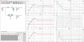
2) Gotten close to a flat FR in vituixCAD with crossover design. I don't like the tweeter playing down so low but have not been able to design steeper filter that works for me. Couldn't get rid of the 2 dB bump around 200 hz so I gave up thinking baffle step might help me with that.
3) Tried using the enclosure tool within VituixCAD. Bass reflex 2.5 cu ft. or 70 liters, I've attached the screenshot.
Problem is I designed the crossover with the 87.5 dB/w sensitivity rating of the mid range and brought down the tweeter a few dB, but the enclosure is now giving me and average SPL of 91 dB for the mid-range. Should I bump up the tweeter again? Or there is some other solution behind this?
Also Is this driver really going to give me a -3 dB of 25 hz? Seems too good to be true. I'm pretty confused so please point me in the right direction.
Your help will be greatly appreciated!
This is my first foray into the DIY World. I'm trying to design a 2 way similar to the Zaph ZRT but with illuminator drivers instead of revelators. Looking for feedback on the steps involved in designing a speaker.
Primary objective: An impedance not lower than 4 ohms minimum to play well with a wide range of amplifiers.
1) I've picked the drivers: D3004/66200 and 18WU/4741TOO.
2) Gotten close to a flat FR in vituixCAD with crossover design. I don't like the tweeter playing down so low but have not been able to design steeper filter that works for me. Couldn't get rid of the 2 dB bump around 200 hz so I gave up thinking baffle step might help me with that.
3) Tried using the enclosure tool within VituixCAD. Bass reflex 2.5 cu ft. or 70 liters, I've attached the screenshot.
Problem is I designed the crossover with the 87.5 dB/w sensitivity rating of the mid range and brought down the tweeter a few dB, but the enclosure is now giving me and average SPL of 91 dB for the mid-range. Should I bump up the tweeter again? Or there is some other solution behind this?
Also Is this driver really going to give me a -3 dB of 25 hz? Seems too good to be true. I'm pretty confused so please point me in the right direction.
Your help will be greatly appreciated!
Attachments
Help me design a room!
- By ndp
- Room Acoustics & Mods
- 29 Replies
I've been doing a little house remodeling and it's finally time to do my dedicated library, and listening area! 12x15' 180 sqft of slam packed literary and auditory bliss.
Walls have a fresh coat of paint, floor is newly carpeted. Doorway is open but can easily be covered with some heavy-duty window treatments, same as the 9Lx6H' window. The mother-in-law does custom drapes and sewing for a living and can make me some nice 3 layer heavy duty drapes at materials cost.
This space should be able to at a minimum comfortably seat two adults and preferably four with an emphasis on comfort. Not really "critical listening" but do like to enjoy high quality audio. I'm a part time cabinet maker/woodworker so shelves, component stands and vinyl storage will all likely be custom built to maximize space.
My first thought was speakers along wall B, seating position 3 feet off of wall D. This limits me to a roughly 80" couch or a few wide chair's, enough seating for two adults. I'm now leaning with larger sectional back 12-15" off of C wall with extremely heavy duty drapes covering the windows. This way I can get four to five adults seated comfortably. This configuration puts the listener five to six feet away from the speaker, is this borderline near field listening?
Anyway that's enough for tonight, I feel like I've written a damn novel. Any and all ideas are greatly welcome and highly appreciated. This will be a slow project, and I'll try and keep some pictures and updates coming as it happens.
Thanks,
ndp
Witch preamp with Aleph 5?
Hello everyone.
I am now finishing the construction of two stereo monaural amplifiers Aleph5.
I would like to use them in the future to drive bi-amping full-range speakers from the Troels Gravsen workshop:
Jenzen CA
I want to use a DAC with storage in a local NAS as a music source.
Now to the question - which Pre-amp to use?
I know that Aleph 5 is not powerful enough in terms of bass, but I would like to take advantage of the low band gain using BIAMP 6-24 ACTIVE CROSSOVER.
I can go the route: DAC -> any pre-amp aka. B1? -> CRS.OVER -> 2x ALEPH5 input -> Subbas + fullrange input speakers.
I'm still undecided with the choice of speakers, but I'd like to keep the requirement for a full-range system, possibly with a bass-horn baffle.
Given that the system will also be used to listen to home theater, I am considering adding subwoofers.
However, I like to hear the experiences of others.
The bottom line is, choose a pre-amp capable of feeding enough as a crossover, as well as a bi-amp connection of Aleph 5 amplifiers.
Thanks for any feedback on both the pre-amp and speaker selection
However, I like to hear the experiences of others.
The conclusion is etak, choose a pre-amp capable of feeding enough both a crossover and a bi-amp connection of Aleph 5 amplifiers.
Thanks for any feedback on both the pre-amp and speaker selection
Attachments
Second build - help deciding on speakers/boxes for a 3 way sealed setup
Hello guys,
last year I finished successfully my TABAQ build, thanks to the help received from the community.
I learned a lot and I would like to progress further with the second build.
The idea is to do three ways with separate boxes and active crossover PC based with an Okto DAC:
I need your help defining the boxes and the speakers, because I lack knowledge. These are my restrictions:
Waiting for your advice! Thanks in advance, cheers
last year I finished successfully my TABAQ build, thanks to the help received from the community.
I learned a lot and I would like to progress further with the second build.
The idea is to do three ways with separate boxes and active crossover PC based with an Okto DAC:
- Woofer up to
120 Hz~250 Hz - Full-range from
120 Hz to 5 KHz~250 Hz Tweeter from 5 KHz
I need your help defining the boxes and the speakers, because I lack knowledge. These are my restrictions:
- I like full-range sound for mids but I prefer tweeters for high frequencies. I will start with a simple WAV setup first, then eventually go for the tweeter if I'm not satisfied.
- The boxes will be stacked up, but I can think about doing a single sub and moving it away. I guess this will require crossing at ~ 80 Hz though.
- Budget per speaker, possibly below 100 €. The cheaper the better, I will compromise if I need to.
- I'd go for sealed boxes if dimensions and frequency response allow it. I would like to go deep to 30 Hz at least.
- My listening includes rock, metal, electronic, ambient and jazz.
Waiting for your advice! Thanks in advance, cheers
Orion 275XTR tweak
Hi guys, I recently bought an orion 275XTR that I would like to dedicate to my subwoofer, before mounting it in the car as always, I opened it and tested it on the bench.
The amp works perfectly, I decided to change all the electrolytics to give it a refresh and since I have a burson V5 classic I was thinking of replacing it with a signal opa.
In the preamp section there are 3 of them (2xjrc4568 and 1x5532), I also noticed in other amplifiers, that even adding only 1 burson (instead of the main opa) the performance improves, certainly lower than the original opa.
Has anyone already made these changes on this orion?
Marantz 1200 Power Amp Board
- By Duke58
- Solid State
- 11 Replies
My beloved Marantz 1200 board was rebuilt, it blew an output and driver transistor, (one of the electrolytic caps was touching one of the pre driver transistors, grounding the circuit). After playing music through the amp for several hours, I noted that the rebuilt board heatsink is warmer than the other channel. Not hot, just warmer.
Output transistors were replaced with new MJ21193 and MJ21194 transistors. One driver transistor and two pre driver transistors were replaced, as well as an electrolytic cap. Reinstalled the board, bias and DC offset were set on both channels and both channels were stable after an hour. I'm going to clean and apply new heat transfer compound and mica insulators on the un-rebuilt channel tomorrow- or should I just let it be?
Output transistors were replaced with new MJ21193 and MJ21194 transistors. One driver transistor and two pre driver transistors were replaced, as well as an electrolytic cap. Reinstalled the board, bias and DC offset were set on both channels and both channels were stable after an hour. I'm going to clean and apply new heat transfer compound and mica insulators on the un-rebuilt channel tomorrow- or should I just let it be?
Desolder gun or pump?
I was wondering if it is worthwhile to add a vacuum pump electric desoldering gun to my tools.I have of course been using the usual handheld pump but I was wondering how much more convenient would a gun be?
For example,is it going to desolder plated thru PCB/components that are very difficult to do?
For example,is it going to desolder plated thru PCB/components that are very difficult to do?
DC Power Supply advice
- By jeffjmr
- Equipment & Tools
- 18 Replies
Looking at Leader 152, HP 6205C, HP 6255A, Topward TPS4000, BK 1651, Heath IP-2718, and GW GPC-3020.
I have a nice BK1743 but now have a need for concurrent + and - and seems I can get one of these two channel units for less than I can get another BK 1743.
Any obvious winners or losers here?
Thanks for any advice on these or another affordable model I may have missed.
Budget is < $100 US and I don’t mind a bit of recapping or tinkering and don’t need lab grade performance.
Jeff
Software for simulating sealed/acoustic suspension boxes
I want to start a project with a sealed 12" woofer. This is my first experience with sealed box.
Can you suggest a good software which correctly takes into account stuffing?
I have the impression that most calculators online do not consider stuffing properly, but I see that this is quite essential to get good results.
Can you suggest a good software which correctly takes into account stuffing?
I have the impression that most calculators online do not consider stuffing properly, but I see that this is quite essential to get good results.
Activating Wilmslow Audio Allegro / Volt/Morel
- By raffajaffa
- Multi-Way
- 17 Replies
Currently have the Volt 2202/Morel Caw/538 ,MD32 tweeter in a passive cabinet .Driven by home built White noise 125 watt stereo amplifier.All vishay and high quality parts.
I would like to go active due to needing better quality louder sound in a much larger room.
Need help and advice as I have seen some half decent active crossover kit both 2 way and 3 way. K M Tech design Burnley UK.
I have enormous amounts of bits left over from previous projects including cabinets heatsinks etc the lot.
My source is now just a modified Denon 3910 player plus an unmodded version.
Passive all vishay Volume pot. (Passion?) All sacd/fi rez as I can still hear the difference.
My thinking was either Use a plate amp ready made for the Volt 2202
and the White noise for mids and also make/purchase a half decent amp for the tweeters.
Possibly 50ish plus watt for tweeters.
Alternative is build another.😱
Probably want to use the existing xover points 450 and 3500? However plate amps Ive seen usually adjustable only up to 200 hz point .
I gather that the Morel mid will go down that deep and is in enclosed portion of speaker cabinet.
Any suggestions thoughts (Volunteers?🙂😀)
thanks in advance 😕
Curcio Audio PC-3R Dynaco ST-70
Brand new blank board, never used. $30 plus a few dollars shipping. Half the price of new.
Send me a PM.
Send me a PM.
WTB-AD1865 DAC PCB Populated or bare
- By MadhaviPrem
- Swap Meet
- 0 Replies
I would like to buy a PCB for my ANK 4.1 DIY DAC. So I am open to a PCB which fits with Audio Note Dac 4.1 or 5.
Thank you
Thank you
Focal 'K' type drivers
I have a number of Focal 'K' drivers, they are mostly NOS I have not seen them for some time but think I have pairs of :-
5k413S
5k013L
6k412L
7k011DBL
10k515
I have at least pairs, and most are unused, I would suggest they are worth something as spares as the Aria kits etc from Zalytron and others used these drivers. I will dig them out if and when I get sufficient interest. Otherwise they will go on EBay at some point. PS. They all have Neoprene surrounds and last time I looked show no signs of age.
A good site for driver parameters is: Very old FOCAL Driver Datasheets - DIY-loudspeakers.com
Alpair 6p vs 6m vs 7.3 for a budget nearfield setup
- By limyang
- Full Range
- 40 Replies
Hi all,
My application is this: on my desk, source is computer, and speakers will be 2-3 feet away from me.
I was extremely tempted to go for the EL70 with dave's mMar-Kel70 to fulfil this application. But I've read great things about MA Alpairs, and I thought, why not step it up?
I'm deciding between the Alpair 6M or 6P in the mMar-Ken6 (http://www.frugal-phile.com/boxlib/P10free/mMar-Ken6-1v0-map-231009.pdf) or the Alpair 7.3 in the Slim Classic GR dMar-Ken7.3 (http://www.frugal-phile.com/boxlib/P10free/CGR-dMar-Ken73-301011.pdf).
From what I've read, the A7.3 is superior to the A6M/P, but I have a few concerns:
1. I know both drivers are good for nearfield (i.e. small room) setups. But at such 'extreme' nearfield range (2-3 feet), is there any significant difference between the A6 and A7.3? Mark specifically identified the A6M as suitable for desk-top usage (he said this in the spec sheet).
2. I intend to run the audio straight from my PC to the Lepai LP 2020A+. This is a less-than-ideal setup, and I do hope to upgrade. But the point is, I heard that the A7.3 is extremely revealing, whilst the A6 is more forgiving. Does this make the A6 more suitable for a budget-constrained audio enthusiast like myself? Or should I aim high with the A7.3 and gradually match the rest of my gear up to it?
Sorry for using such vague terms, I have not come to terms with most of the technicalities yet.
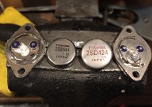
Capacitor Question
- Car Audio
- 1 Replies
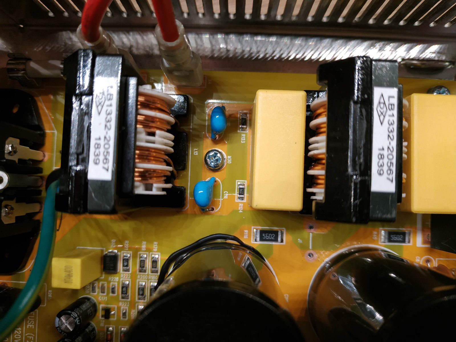
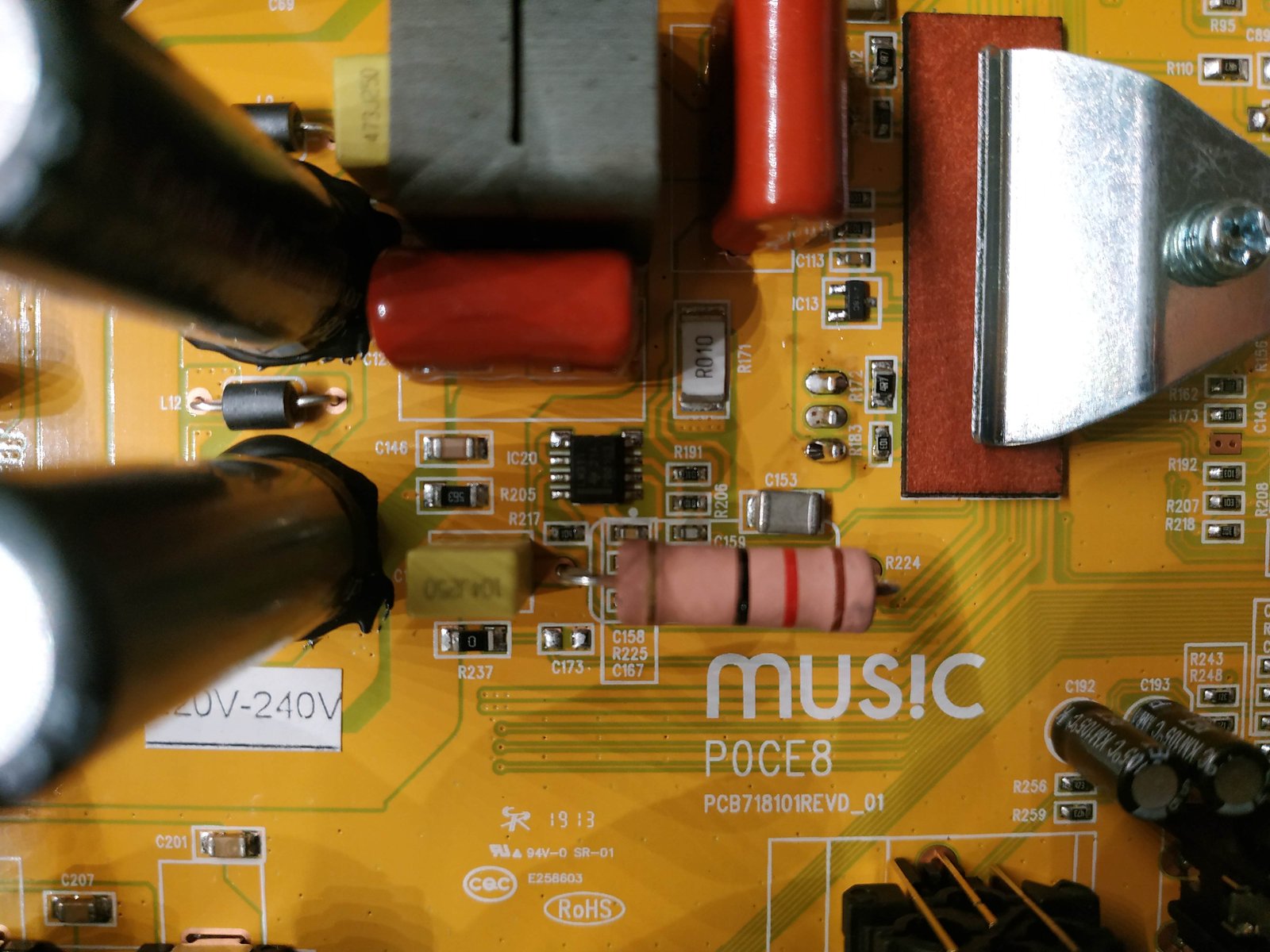
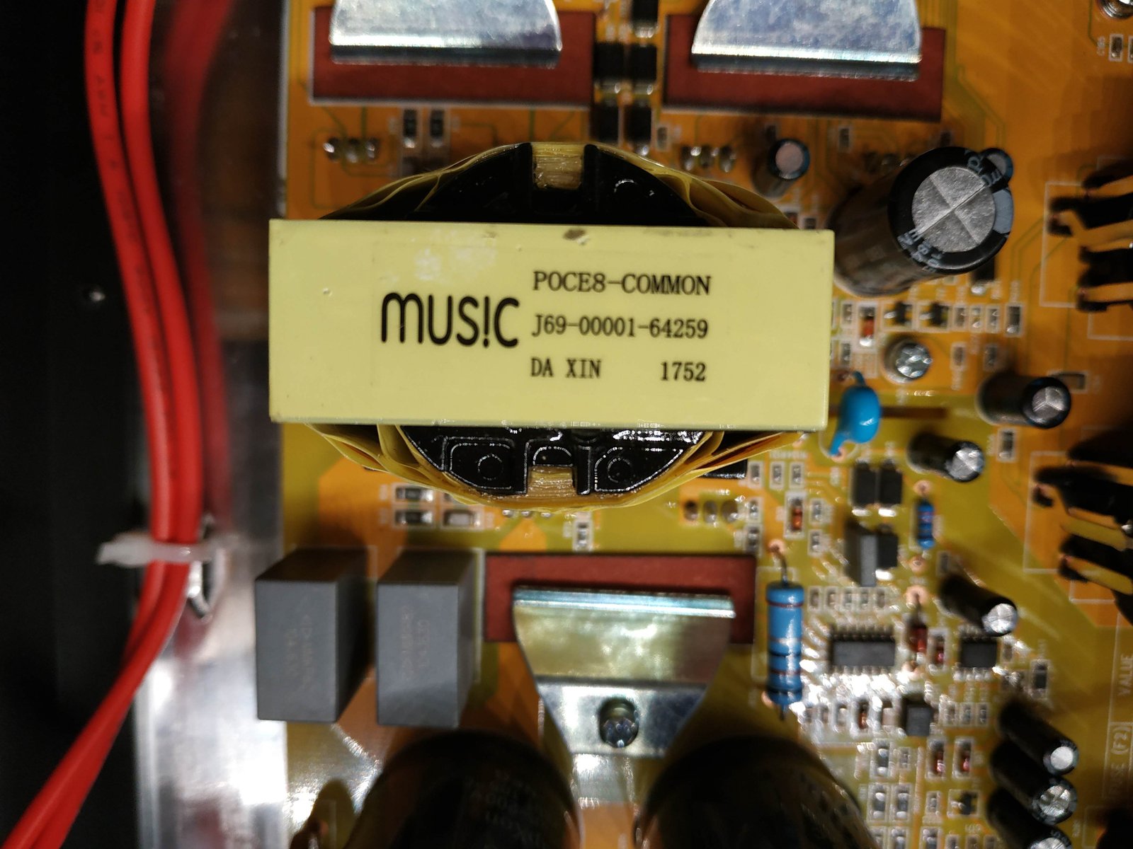
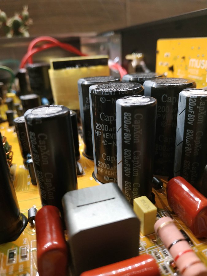
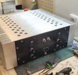
Are these just regular film caps or are they tantalum capacitors?
There’s no + sign on the cap
There’s no + sign on the cap
Attachments
Technics SU-CH700 no output.
- By hugocarmo
- Solid State
- 0 Replies
Hello everybody.
I´m new to this forum, I´m seeking some advice on repairing, if possible my old but loved Technics SC-CH700 system.
The problem is in the SU-CH700 Amplifier unit.
I´ts been working fine till it started cutting off on an certain volume level.
I searched the web and one of the solutions was soldering a 10nf ceramic capacitor on the pins of the fan socket.
I did that, when I plugged the system to AC, when I pressed the power button I saw the fan started imediately to work, I thought it was normal, but then when I chose the cd or the tuner there´s no sound from the speakers or the headphone, the only thing that I can hear from the speakers is a buzzing sound that seems ths sound of the fan motor.
I removed the capacitor, but the problem persisted.
I noticed that the IC LC7536 on the side board is getting to hot when I touch it, I dont know if its normal because I never touched it before.
What could it be?
Can someone help me? I have the service manual if needed.
Thank you all in advance,
Hugo do Carmo.
valve protectors (cat!)
- By adamus
- Tubes / Valves
- 25 Replies
Wilbur, a ragdoll cat with learning difficulties will at some point, without doubt, attempt to lick the exposed valves. Playing this forward, that could be the end of wilbur. The wife would probably upsticks too. All of that is bad.
All jokes aside about the retarded cat..
Anyone know of either a diy solution that looks pretty (i dont want a mesh box over them), or a source of valve protectors.
One very annoying rule - I hate the look of the stacked rings you can get on fleabay / aliexpress.
On commercial offerings, i see glass tubes, they look nice, but i cant find any for sale.
ideas welcome.
Chipamp appropriate for +-70v
I have an 80s guitar amp that I want to use as a doner for a fresh build. Basically the poweramp is a sealed unit and makes unpleasant distorted noises and the preamp is a little worse. The chassis, cab, speaker and reverb tank are all in good order.
And there's a power supply, obviously.
I was hoping to drop a simple chipamp in the place of the current power amp, and then front it with a nice preamp circuit, but the power supply is a lot beefier than I expected. It's labelled primary 22a 34v but my mains voltage is 240v, so I'm reading +-70v dc after the rectifier.
I've used an LM3886 in a project before, but the datasheet is quite clear that this voltage will melt it. Should I just swap the transformer, or is there a suitable chip I can throw in here?
F6 Power
- By steppenwolf2
- Pass Labs
- 10 Replies
hello,
i have order at diy store all what i could buy there to building the f6. i look at the guide 6l6 but for me isn't 100% what i should need for parts between toroid and power supply.
one guy from netherland wrote.
You need rectifiers between toroid and power supply, also simple protection circuit.
okay, but what is it excatly and where can i see it in the guide from 6L6?
Other problem is, my english isn't good enough to understand all 🙁
Thanks for our help.
WTB - DAC with Tube output
Hi, I am looking for a new DAC and want to see if anyone would like to sell their project/setup. Ideally I would like to get a multibit DAC with a Tube output stage, but open to other suggestions so feel free to offer.
There is a TDA1541 kit for sale on the forum, but unfortunately it can only accept a SPDIF input, while I need also USB (which can also be the option to add a USB card which i can add myself).
There is a TDA1541 kit for sale on the forum, but unfortunately it can only accept a SPDIF input, while I need also USB (which can also be the option to add a USB card which i can add myself).
funky jfets?
I just picked up a pass kit in the swap meet a while ago and the toshiba jfets were included...
here are some pics.
the 2sk170 look normal but the other 2 have absolutely no writing on them. has anyone seen these?
Can I assume they are the j counterparts of the 170's?
are they real?
Apparently they came from someone named Spencer?
Thanks in advance!!
here are some pics.
the 2sk170 look normal but the other 2 have absolutely no writing on them. has anyone seen these?
Can I assume they are the j counterparts of the 170's?
are they real?
Apparently they came from someone named Spencer?
Thanks in advance!!
Attachments
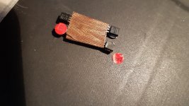
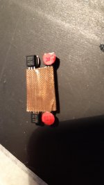
AT2380v1 // 2 Channels digitally controlled stepped attenuator
- By Frex
- Equipment & Tools
- 121 Replies
Hello all,
Here is my new little DIYproject, the "AT2380".
As many DIYers here, i often needed to attenuate a signal to fit better with the input level of the target system.
This is a tool that i need to perform some tests on my other design, the AA2380 ADC.
So, i was thinking to building an attenuator for a long time.
There is of course some already built, but good attenuators are generally dedicated for RF application with 50/75 Ohms impedance.
This is a too low impedance for the main audio and instrumentation applications that i target.
I work on this project for some months now, in parallel with some others.
I designed it to meet my needs and to be a cost effective solution to share it with all interested DIYers.
The main specifications of the attenuator are :
These specs are preliminary as i don't have yet tested it, but it's the target.
Each attenuator channel use a ladder resistors design switched by 8 relays.
So, with 0.5dB resolution the attenuation can be controlled over 0 to -127.5 dB range.
(You can see how work a ladder log attenuator and calculate value here.)
The control of the attenuation is done by a rotary encoder with push button.
For easiest setting, the dB step by encoder increment can be choose between 0.5-1-3-6 or 10 dB.
The actual attenuation level is show on a 7 segments led display.
There is also the possibility to use it in tracking level mode.
When this mode is enabled, the output level of the attenuator track the desired level needed in the range of +10dBV to -90dBV (3Vrms to 30µVrms).
At this time, the prototype PCB has been send for manufacturing and i will have it in next week.
I will post a picture as soon it is in my hands.
You can show below the synoptic of the design :
Others infos will follow soon, and i hope that the project will interest others DIYers.
Regards.
Update of the 20/11/2017
------------------------------------
FInal V2.0 released
The full schematic and the manual of the attenuator is available below :
Full schematics : AT2380v2_sch.pdf
Operating manual and specifications : AT2380V1_Manual_v0.pdf
Functional Synoptic :
AT2380v2 functional synoptic
Complete BOM file for both track and not rack, with Mouser price list :
AT2380v2 full bill of material with Mouser price list
I finalize the Gerbers files, and the group-buy for bare PCB will be open on next week-end.
More infos soon. 🙂
Update of the 26/11/2017 -- PCB GroupBuy started
---------------------------------------------------------------------------
The PCB group buy is started and can be found here :
AT2380v2 2Ch Digitally controlled Stepped Attenuator
Update of the 30/01/2018 -- Firmware Update. (v0.23)
---------------------------------------------------------------------------
I released today the new 0.23 CPLD firmware that solve some bugs and add new features :
- Version display at startup
- Calibration mode.
- Relays fast mode operation (for audio volume control applications)
- Bluetooth UART mode attenuator control
Because of these many modifications, i have made a new design folder (v2.1),
provided to all PCB owners.
Some files are available to download on the links below :
AT2380_SynopticV2.1
AT2380v2.1_schematics
AT2380_Manualv1.1
AT2380V2_Bill_of_material_Rev1
Note that bare PCB are available, if interested send me a PM.
Frex
Here is my new little DIYproject, the "AT2380".
As many DIYers here, i often needed to attenuate a signal to fit better with the input level of the target system.
This is a tool that i need to perform some tests on my other design, the AA2380 ADC.
So, i was thinking to building an attenuator for a long time.
There is of course some already built, but good attenuators are generally dedicated for RF application with 50/75 Ohms impedance.
This is a too low impedance for the main audio and instrumentation applications that i target.
I work on this project for some months now, in parallel with some others.
I designed it to meet my needs and to be a cost effective solution to share it with all interested DIYers.
The main specifications of the attenuator are :
- full digital control (5M570 CPLD, VHDL coded).
- 2 pseudo isolated attenuators Channels
- Zin= 600 Ohms , Zout = ~ 0 to 300 Ohms (customizable)
- Flat frequency response (± 0,05dB) from at least DC..1MHz (± 3dB to 10 MHz).
- 0 to 127,5 dB attenuation in 0,5 dB step (8 bits / 256 steps)
- Direct dB attenuation setting displayed on 4 digits seven segments LEDs.
- Five selectable dB steps : 0.5 ,1 , 3, 6 and 10 dB by encoder increment.
- Optional output level auto-tracking mode from +10 dBV to – 85 dBV (attenuation only) .
- Full internal clock enable switch, for ultra quiet operation mode.
- Calibration mode for dBV measurement
- Relay fast refresh mode for audio volume control application
- Bluetooth UART link to control attenuator and measure output dBV level
- Shielded design to improve RF performance and noise immunity .
- Low cost design and easy to find parts.
- 100x160mm PCB size, fit in Hammond 1455 series extruded aluminum enclosure.
- Front and rear panel made in PCB will all holes drilled and with gold silkscreen.
- Through holes axial or SMD (1206) ladder attenuator resistors types.
These specs are preliminary as i don't have yet tested it, but it's the target.
Each attenuator channel use a ladder resistors design switched by 8 relays.
So, with 0.5dB resolution the attenuation can be controlled over 0 to -127.5 dB range.
(You can see how work a ladder log attenuator and calculate value here.)
The control of the attenuation is done by a rotary encoder with push button.
For easiest setting, the dB step by encoder increment can be choose between 0.5-1-3-6 or 10 dB.
The actual attenuation level is show on a 7 segments led display.
There is also the possibility to use it in tracking level mode.
When this mode is enabled, the output level of the attenuator track the desired level needed in the range of +10dBV to -90dBV (3Vrms to 30µVrms).
At this time, the prototype PCB has been send for manufacturing and i will have it in next week.
I will post a picture as soon it is in my hands.
You can show below the synoptic of the design :
Others infos will follow soon, and i hope that the project will interest others DIYers.
Regards.
Update of the 20/11/2017
------------------------------------
FInal V2.0 released
The full schematic and the manual of the attenuator is available below :
Full schematics : AT2380v2_sch.pdf
Operating manual and specifications : AT2380V1_Manual_v0.pdf
Functional Synoptic :
AT2380v2 functional synoptic
Complete BOM file for both track and not rack, with Mouser price list :
AT2380v2 full bill of material with Mouser price list
I finalize the Gerbers files, and the group-buy for bare PCB will be open on next week-end.
More infos soon. 🙂
Update of the 26/11/2017 -- PCB GroupBuy started
---------------------------------------------------------------------------
The PCB group buy is started and can be found here :
AT2380v2 2Ch Digitally controlled Stepped Attenuator
Update of the 30/01/2018 -- Firmware Update. (v0.23)
---------------------------------------------------------------------------
I released today the new 0.23 CPLD firmware that solve some bugs and add new features :
- Version display at startup
- Calibration mode.
- Relays fast mode operation (for audio volume control applications)
- Bluetooth UART mode attenuator control
Because of these many modifications, i have made a new design folder (v2.1),
provided to all PCB owners.
Some files are available to download on the links below :
AT2380_SynopticV2.1
AT2380v2.1_schematics
AT2380_Manualv1.1
AT2380V2_Bill_of_material_Rev1
Note that bare PCB are available, if interested send me a PM.
Frex
FS Tangband W6-1139sif PAIRS
Hi, I have for sale 3x PAIRS of Tangband W6-1139sif in used but 100% working condition. Domestic HiFi use not thrashed in car audio!
£110 per pair including UK shipping. Happy to ship worldwide at cost.
Thanks for looking!
£110 per pair including UK shipping. Happy to ship worldwide at cost.
Thanks for looking!
FS PAIR SEAS 27TBFC/G tweeters NEW
Hello, I have for sale a pair of SEAS 27TBFC/G metal dome tweeters.
These were purchased for a project but I have moved in a different direction so they were never used.
£75 inc. postage
Thanks for looking.
These were purchased for a project but I have moved in a different direction so they were never used.
£75 inc. postage
Thanks for looking.
Soundigital Parts
I have access to some Soundigital parts, mainly fets for the power supply and some for the class D section of the large amps such as 8K, 12K, 20K and 35K.
I can also flash the older 35K amps to with the latest hex.
Pm me for what you need.
I can also flash the older 35K amps to with the latest hex.
Pm me for what you need.
NAD preamp 1240 distortion
- By rmgvs
- Solid State
- 25 Replies
I just bought a secondhand NAD preamp type 1240 (probably made around 1985-1990). I have no schematics and have a problem with the amp. The amp distorts prematurely and does not have enough gain/amplification. The problem is in the line-stage on all inputs and in both channels. First guess was that the power supply was not okay: but here I measure a nice plus/minus 20 Volts after rectification and including stabilization.
In the signal path there is an opamp type JRC 2043D around the tone controls and further there are a number of normal BC5xx small transistors. Maybe the opamp is the problem but why then should the problem be there in both channels? Not so likely. But if one of the small transistors is the problem, the same applies. Passive components? They look okay to me, no burnt resistors and the like, no loose solder joints.
Who has any idea what can be the cause of this problem?
Link for Frugel-Horn XL plan
- By nasrudin84
- Full Range
- 1 Replies
Hello, I 'm looking for the Frugel-Horn XL plan and can't find a good link.
404 Error - Page Not Found doesn't work. Any idea ?
I've got a pair of lii-audio fast8. Here it is :
One Pair | New 8" Fullrange Drivers | Fine and clear sound | Fast-8 - Lii Audio, unique speaker, amplfier, quality and cost-saving parts for HiFi DIY
404 Error - Page Not Found doesn't work. Any idea ?
I've got a pair of lii-audio fast8. Here it is :
One Pair | New 8" Fullrange Drivers | Fine and clear sound | Fast-8 - Lii Audio, unique speaker, amplfier, quality and cost-saving parts for HiFi DIY
FS: Micro Seiki RX1500 turntable
For sale this very nice turntable that I bought new quite some time ago, It has a free-standing motor.
Currently it has a Ortofon VirtusII cart installed.
PM me if there is any interest.
Beside the turntable there is a collection of about 10.000 LP's with pop, Jazz, folk and ~70% classical music.
Currently it has a Ortofon VirtusII cart installed.
PM me if there is any interest.
Beside the turntable there is a collection of about 10.000 LP's with pop, Jazz, folk and ~70% classical music.
Fs: SEAS Excel E0011-06 T25CF002 Millennium Tweeter
I am selling SEAS Excel T25CF-002 (E0011) Millennium Tweeter with 15 hours of use so they are totally new.
The price is 330 € + shipping


The price is 330 € + shipping
headphone amplifier
- Solid State
- 4 Replies
I am making one amplifier for my headphones
Intention is to make a P3A with low voltage and high bias
willing to install this amp in the rack , run a cable for 2 ch next to my couch which is about 7-10 meters
then construct a local box with the plug a passive attenuator of 2W-5W in order to be able to control the volume localy
so in the output of the amplifier which originally is specified for 8 R and speakers i will feed :
--the 10 meter cable
--A set of resistors for headphone attenuation Expect 220R /2W in series and something may be in parallel ( advise needed )
--100 R 2-5 W potensiometer
--set of headphones 32 R
I was thinking may be a local Zobel
Do you expect an stability issues with that configuration ?
Is there anything else to treat my output with ?
thank you
wtd: SSHV 1 or 2 pcb or module from uk or europe
Hi does anyone have any spare PCBs for the SSHV2 or 1 (salas high volt shunt), or complete modules for sale
I am uk based.
Thanks
I am uk based.
Thanks
Does DSP delay equal physical tweeter set back on baffle?
Curious about this as it seems to me that delaying the tweeter output would be the same as setting the tweeter back on the baffle to preserve the time domain...but I'm not sure hence this question.
Thanks for any replies.
Thanks for any replies.
WTB: Pellegrene waveguide for Transducer Lab tweeter
Does anyone have those 7" x 5" waveguides that Dave designed for the Transducer Lab tweeters? I would like to get a pair.
TDA2030/2050 Single Supply Amplifier
- Chip Amps
- 9 Replies
Hi Friends PCB Layout of tda2030/2050 Single supply amplifier.
Too late edit in picture, Use 680Ω resistance instead of 68Ω
Too late edit in picture, Use 680Ω resistance instead of 68Ω
Attachments
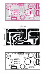
TU-8600S Build Question
Iʻm installing the electrolytic capacitors. The instructions call for 5 each 4700uF 16V. My kit came with 5 each 8200uF 16V. Is it ok to use these? Thanks!
My LM3886 AMP OLD STORY
- Chip Amps
- 0 Replies
I like the amp by solid tube, the D class don't have good sound field .
The is chip amp just the reference amp to my other type amp.
The is chip amp just the reference amp to my other type amp.
An externally hosted image should be here but it was not working when we last tested it.
Preamp rebuild help . $$$$$
- By Kennyj
- Analog Line Level
- 1 Replies
Hello , not sure if this is the spot to post or even the forum/wensite but here goes..
I have had nothing but great info and knowledge passed on to me from here. I was now wonedering if you could pass some more ?
Sooo if I were to take some detailed nudes of my preamp (magus mfa ) and post them with a parts and labour list buy of refresh and upgrade that are recomemded buy the creator of my pre (so tested and true ) would any one here be interested in helping me A-order the stuff to do it plus some new potentiometers that arent on the list B- take a screen shot of my pre and PS and circle what goes where , then send it back . I know. I know it should be easy .Im pretty good but have only did some small cap replacements What with all thats going on i didnt plan on doing it my self but...
I dont want this for free . Ill etransfer 1/2 up front . This kinda thing for the right person is 20 min . Please let me know your thoughts . Thanks every one
Ken
Laser head For Nuprime CDT-8PRO
- By vadimgal
- Digital Source
- 2 Replies
Hello,
Does anybody know what the laser head is in Nuprime CD T-8PRO Transport?
On official website they said Sony KHM 313 , but is not correct.
Thanks.
Does anybody know what the laser head is in Nuprime CD T-8PRO Transport?
On official website they said Sony KHM 313 , but is not correct.
Thanks.
Audax, Vifa, Seas, Peerless, Polydax, AR, NHT drivers
- By ronhorowitz
- Swap Meet
- 1 Replies
Hey, Guys,
Doing a little closet cleaning and have a bunch of drivers to sell off:
4x AR 1210064-08 1" dome
1x AR 1-210155-2 5.25"
Pr. Audax AT170ZGP W08ZGP 6.5" treated paper, rubber surround
Pr. Audax HT110G0 5" treated paper, rubber
1x Audax TW037Y0 dome mid
1x NHT 1-11-043-1 6.5"
1x NHT 11-001-03 4.5"
Pr. NHT 1" dome, shielded
Pr. Nokia 4" paper, shielded
Pr. Peerless 1" domes, shielded
Pr. 1" domes "Star Trek / Ouija board" faceplate
1x Polydax 4" paper, shielded
Pr. Polydax HIF17JVX2CA12 6.5"
Pr. Seas D20TD-05 3/4" domes
Pr. Tonegen 8", poly, rubber
4x Tonegen 4", treated paper, in enclosures
Pr. Tonegen .75" dome
Pr. Vifa 6.5" molded plastic frames
Pr. Vifa 6.5" molded plastic frames, bucking magnets
Pr. Vifa 6.5" molded plastic frames, shield cans
Pr. Vifa TC26SF05-06 1" dome
Pr. Vifa 3.5" poly, rubber
No- name 12", heavy steel frame, bunch of other stuff, just tired of writing. Might be a little off on some of the details, but you get the gist. I'd like to get $200 for the lot. Available for pickup in Richmond, CA most weekends. For $100 more, I'll through in a bunch of 6.5" and 8" woofers.
Anyone want to pick them up?
distance from power supply and amp module
- By datrumole
- Construction Tips
- 3 Replies
hey all,
been searching for a few days on this topic, nothing totally dedicated that i can find so apologies if this has been discussed else where at length
have (2) L20.5 amp modules, and (2) SMPS to power them. is there a required distance they should be away from one another in the same enclosure? the amp modules will be mounted vertically on the enclosure's side heat sinks, while the SMPS will be mounted horizontally (so perpendicular to one another) and the space is somewhat tight, probably 2 or so inches from one another. will this be problematic?
diagram for Magnum-sa12 professional amplifier - SENIA Music echiv 1200 MachAudio
- By seditiouss
- Solid State
- 17 Replies
Helo,guys !
Do anybody has diagram for Magnum-sa12 professional amplifier - SENIA Music echivalent 1200 MachAudio - MJL 1302A / MJL3281A
Thks in advance
Do anybody has diagram for Magnum-sa12 professional amplifier - SENIA Music echivalent 1200 MachAudio - MJL 1302A / MJL3281A
Thks in advance
Attachments
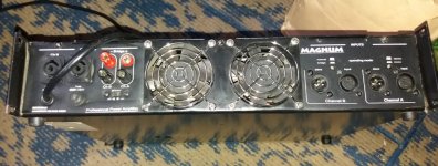
Load more
Projects by fanatics, for fanatics
Get answers and advice for everyone wanting to learn the art of audio.
Join the Community
507,837
Members
7,890,262
Messages