Si vs Ge transistor buffer circuit

Hi all, I found that adding an input buffer circuit to my darlington rangemaster guitar pedal design greatly improves impedance matching to the pickups. I am currently using the input buffer circuit from a turbo tube screamer wich is a silicon transistor.

Would there be a practical way to design an input buffer circuit using an NPN germanium transistor? Would a germanium transistor inherently have lower input impedance? Furthermore, would a JFET inherently have a higher input impedance?

Attached is the current Si buffer circuit I am using.
BJT buffer.png

Using an opamp for an active reamp box

1738286448840.png

The majority of suggestions for a guitar reamp box is to use a transformer like in this classic example.

❔ Is there a reason that op amps unity gain or other are not typically suggested?

It is my very top level understanding that "ideally" opamps have a near infinite input impedance and near zero output impedance and that placing a resistor in parallel near the input and output, one could effectively set an impedance of their choosing. If this is accurate, couldn't one just place a parallel resistor R1 in front of the opamp that is 10 times greater than the output of their audio interface and then on the output place a 10k resistor on the output side R4 to match what an EMG 80/81 is?

I am aware I am missing some capacitors to block dc, etc in this crude drawing.

Using a transformer has the benefits of having a passive device and not need to worry about a power source.
But if you intended to designing an "active" reamp box that could have additional features such a analog/digital VU meter, etc, the power source would already be there.

Safety about My Ground Loop Breaker design

Hello everyone.

I'm currently designing some amplifier with mains-powered linear transformer supply.
While working on my design, the idea hit my head and I suddenly created Ground Breaker circuit.
Here's the simplified schematic of my design.

groundloop_breaker_demo.PNG


In here above schematic,

GND is reference zero-volt of amplifier circuits.

Earth is earth from mains power, connected to chassis of appliance and can be used to shield EMF.

R1 and R2 represents to load of external circuits.

Note that transformer T1 is linear step-down transformer, with power rated up to 56 VA.
Mains power input would be 230VAC 60Hz.

C1 is Class-Y2 rated Film type capacitor. It bypass high frequency noises. Also would be helpful to suppress voltage spikes.

When voltage difference between Earth and GND is small than Forward voltage of Diodes(D1, D2), in general situation, small current pass through R3.

D1 and D2 would bypass high current when appliance encountered to failure. It should have ability to drain hundreds amps continuously. Also it's good to use low Vf diode as possible.
These diodes are critically important to protect user and device itself to safe.

Lastly, D3 is Bi-directional TVS diode, dissipate short-period voltage spike as heat when ESD event happens.


If my design above works as I intended, it will provide noise reduction from mains earth, while also keep user safe when appliance fails.
I'm really curious about performance and safety of this schematic.
Would this design pass any regulation of international or local standards?

It will be thankful to get any kind of advice here.
Thanks in advance.

Fishman Loudbox Artist Amp

Hello everyone,

I am from Argentina, here we have 220/240 volts electricity. I have a Fishman Artist wire for 120 volts, I purchased new in the USA. Here in Argentina it works perfect with a step down converter. There is a power board that can be rewired with a jumper wire to switch voltage and change the fuse to 1amp, My question is, Is that all it needs to be done to work in 240 volts? Or It needs other electronics to be change? Did someone did this?

Attachments

  • Fishman power board botton.jpg
    Fishman power board botton.jpg
    119.7 KB · Views: 109
  • Fishman Power board.jpg
    Fishman Power board.jpg
    199.4 KB · Views: 93
  • Fishman transformer.jpg
    Fishman transformer.jpg
    238.2 KB · Views: 102

For Sale Aluminum Enclosure for EMI/Power Filter

SOLD
Recently purchased an aluminum enclosure for building a mains power filter using Fo-Felix boards. I ended up making a custom enclosure as my needs changed.

The enclosure is unused and is still in the packaging received from China. I paid $145 including shipping and taxes. Can sell it for --- plus the cost of shipping (UPS/Fedex Ground) within the United States.

The dimensions are
External:
Width = 320 mm
Height = 120 mm
Depth = 265 mm

Internal:
Width = 300 mm
Height = 112 mm
Depth = 203.5 mm

Send me a message if you are interested.

Thanks!
Subbu

Attachments

  • 1.jpg
    1.jpg
    31.2 KB · Views: 132
  • 2.jpg
    2.jpg
    28.7 KB · Views: 125
  • 3.jpg
    3.jpg
    22.1 KB · Views: 117
  • 4.jpg
    4.jpg
    33.5 KB · Views: 124

Help me understand a ground loop problem when using a QA401

Hello All,

Briefly, the problem is, when both the input and output grounds of a QA401 are connected to an amplifier, there is more 60-cycle related noise than if only one of these grounds is connected.

The first attachment shows the equipment setup I am using. Note that the connection between the QA401 Input and the amplifier output is either A or B. All other connections remain as shown, except when measuring the amplifier with a shorted input, so no connection to the QA401’s input is used.

The second attachment shows the amplifier’s grounding topology.

The third attachment shows the amplifier’s output with a shorted input.

The fourth attachment shows the amplifier’s output when connected using the “A” option.

The fifth attachment shows the amplifier’s output when connected using the “B” option.

These measurements were collected with an unpowered QA401. The results are the same if the QA401 is powered, except for a bit more white noise.

I tested the possibility that a ground loop might go through the DSO by disconnecting it and looking at the amplifier’s distortion spectrum.

The sixth and seventh attachments shows the distortion spectrum using the “A” and “B” options, respectively.

That is a lot of material, I hope someone can make sense of it for me.

Thanks in advance for any suggestions.

Cheers,
ceulrich

Attachments

  • Equipment Setup.png
    Equipment Setup.png
    49.1 KB · Views: 186
  • Grounding Topology.png
    Grounding Topology.png
    18.9 KB · Views: 189
  • Shorted Input.jpg
    Shorted Input.jpg
    26.3 KB · Views: 165
  • A Option.jpg
    A Option.jpg
    231.1 KB · Views: 116
  • B Option.jpg
    B Option.jpg
    26.2 KB · Views: 172
  • Dist Spec - A Option.pdf
    Dist Spec - A Option.pdf
    29.5 KB · Views: 68
  • Dist Spec - B Option.pdf
    Dist Spec - B Option.pdf
    26.6 KB · Views: 65

  • Locked
PCC88 heater current vs. voltage

The PCC88 tube is often claimed to be a direct replacement for the ECC88 / 6DJ8 tube. However, the heater of the PCC88 is specified to operate from a set current (300 mA), while the ECC88 / 6DJ8 heater is specified for a set voltage (6.3 V). So, replacing an ECC88 / 6DJ8 with a PCC88 usually results in the PCC88 operating with 6.3 V heater supply designed for the ECC88 / 6DJ8.

Is this a problem? I read a lot about this subject on the interwebs, but I found no clear answer. So I pulled out a few PCC88 from my boxes and did some measurements. First of all, I measured the heater voltages that develop from different heater currents. The readings were taken from five old, unused Philips PCC88 tubes. The readings were quite consistent across the five samples, and I'll just show the means across all five samples. I attached the full data for those who want to take a look.

PCC88_Ih_vs_Vh.png


It's quite obvious that at the nominal rating of 300 mA heater current one does not get 6.3 V. Vice versa, by applying a heater voltage of 6.3 V, the heater current comes out at 263 mA, quite a bit below the nominal spec.

While 6.3 V on the heater won't kill the tube, it might affect its operation. I measured the characteristic curves and compared the same tube operating at the nominal spec (300 mA) and at a typical ECC88 / 6DJ8 situation (6.3 V):
PCC88_curves_Ih=300mA_vs_Vh=6.3V.png

The curves are not very different, but they are also not the same. You might not notice straightaway, but the grid voltage between the two curve sets is offset by about 0.5 V (the grid voltage labels pertain to the blue curves only, the red curves have no labels). This means the bias / operating points will be offset accordingly. For example, if the tube is biased at 100 V anode voltage and -2.5 V grid voltage, the plate current will be 10 mA with 300 mA heater current, or about 6..7 mA with 6.3 V on the heater. Also, at lower plate voltages, the curves with the nominal heater spec (300 mA) are a bit steeper than those with the ECC88/ 6DJ8 spec (6.3 V).

So, there you have it:
No, the PCC88 is not a 100% equivalent of the ECC88 / 6DJ8 due to it's different heater.
Yes, the PCC88 may work as a replacement for an ECC88 / 6DJ8 -- but I can't tell if it works well enough for you in any given application. Hopefully my measurements will help you to figure things out.

Attachments

For Sale F6

In the past year I’ve moved to an active system utilizing streaming. Therefore I’m selling some equipment. This F6 has been excellent and I would like to sell it. More pictures and details for those who are interested
Considering the time, effort and results I think $1000 plus shipping is fair

Attachments

  • IMG_0342.jpeg
    IMG_0342.jpeg
    223.4 KB · Views: 640
  • IMG_0326.jpeg
    IMG_0326.jpeg
    401.5 KB · Views: 644
  • Like
Reactions: mordikai

Audio Transformer Emulation - Gyrator-Capacitor

I am currently working on implementing a gyrator-capacitor model in LTspice to simulate the saturation and hysteresis of magnetic cores in audio transformers.

In the attached files, you will find a library for modeling a gyrator-capacitor, along with single-ended and push-pull transformer models and examples.

I would greatly appreciate any help in improving the transformer models.

The parameters in xformer.lib were calibrated using a tool I developed. I have successfully implemented this model in a state-space simulation software I built, but I would like to adapt it for LTspice to validate its performance.

I am an enthusiast with a basic understanding of electrical engineering, and I would be grateful for your support.

DIY Class A Headphone Amp suggestion

Hello,
I am looking forward to build a headphone amplifier and looking for a project/schematic I could use as a reference. I am looking for the following:
  • capable of driving a pair of Beyerdynamic DT880 250 Ohm which I am using at the moment (if possible also the 600Ohm version), probably will upgrade later
  • Class A (the single ended class a topology or in genereal the designs by Nelson Pass really appeal to me 🙂 )
  • external PSU prefered
  • parts which are available at the known large distributors, if possible also in a few years
  • maximum size around 200x200x50mm
For me its okay to do the PCB layout by myself/use SMD components to shrink the needed size a bit (and accept maybe a bit less performance)

At the moment I have seen:
  • ACP+ (needs to be modified for 250Ohm impedance)
  • AMB M³ ("active ground technology" which is new for me)
  • Whammy (internal PSU, therefore quite large)
Shipping for kits is really expensive, so a bit more DIY would be less expensive (and more fun😉)
Do you have any recommendations?
Thank you!

Best
Florian

Experience with VIFA NE123W?

This is a relatively new driver, a 4 inch "wide band woofer" which would probably be suitable as a midrange, which is what I'm considering. Anyone have any experience or opinion? The physical configuration looks to be a smaller knock-off of the Satori MW13P with not quite as elegant a finish, but with some of the same functional features.

I'm looking for a really good 4" midrange (who isn't?) after struggling with some mediocre polypro cone drivers for too many years.

Peace,
Tom E

Punch 40ix

Hi, I'm new on the forum and I'm hoping you can help me out, I have a punch 40ix with only one channel working so what I did was to check the Output Mosfet and it was bad (Q215)BUZZ11 so I replaced it with a new one and it worked for a minute and then no sound again, so I disconnected the power and check the FET and it was grounded so now the question is what do I need to check before I put a new one and burn it again? thank you guys for all your help.

Mini Karlsonator (0.53X) with Dual TC9FDs

Edit Nov 30, 2021: Andrewbee posted plans (that he got somewhere on DIYA, we thank the author whoever you are) for a Karlsonator for the W5-2143. I don’t remember the simulation on this one but I have literally done hundreds so would not surprise me if I forgot. Looks like a taller aspect ratio and that makes sense as this driver has a lower Qts and more powerful motor.
https://www.diyaudio.com/forums/attachment.php?attachmentid=1001541&d=1638274724

Edit Jan 16, 2021: A beautiful example of dual 3FE25-16 Karlsonator by Ripson. He went all out and covered them with repurposed antique pine from a barn and made grill too:
grille.jpg


Edit July 3, 2020: Gecko made a beautiful foamcore 0.53x with PA130-8 and cherry aperture:
ACtC-3f6ji8A5bz2bwQ3vzBA393tRTcgoEh127UDNGDUXxRuCxKEuSOe4z4RlnknWiXWUPFUZAwIMoTdKLX_JF4DIuxHazWWRW4taMOl7-QLGHzb5cwX99X7PJkotFwZm_6--9iDGjRreb5M4OHIhNjhkv34kw=w952-h1171-no


Edit Feb 10, 2020: super 0.4x* build by vox with 3FE22:
815877d1581326429-mini-karlsonator-0-53x-dual-tc9fds-07614d6c-9f99-4751-8276-03a0ec318f40-jpeg

*scale slightly smaller than 0.4x

Edit Feb 6, 2020: just managed to locate nice plans by Skylar88 for dual 3FE25’s:
634541d1504988311-aca-speaker-short-list-capture-jpg


Edit Dec 16, 2019: tips on adding sound dampening foam for wooden mini Karlsonators here
Mini Karlsonator (0.53X) with Dual TC9FD's

Edit June 23, 2019: 0.53x Karlsonator plans in BB plywood by Jhofland here:
Mini Karlsonator (0.53X) with Dual TC9FD's

Edit: Feb25, 2018 - New "Score and Fold" CAD plans of 0.53x Karlsonator by Mudjester in metric and English units! A huge thank you to Mudjester for making this very comprehensive planset - one of the best I have seen ever!. These plans are in 1:4 scale in case you want to print out and use a ruler to measure and scale. Thread discussion here.
Metric:
http://www.diyaudio.com/forums/atta...fds-0-53x-karlsonator-score-fold-plans-mm-pdf

Engish:
http://www.diyaudio.com/forums/atta...tc9fds-0-53x-karlsonator-score-fold-plans-pdf


Edit (Apr 29, 2015): Latest 0.40x K'nator Score-N-Fold Plans by Mudjester available here: https://www.diyaudio.com/community/attachments/0-4x_karlsonator_plans-pdf.1027626/

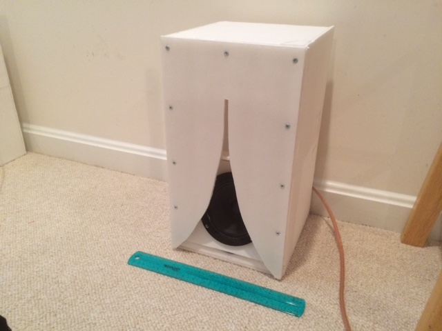
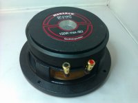
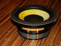
EDIT (Mar 29, 2015): The Dayton PA130-8 driver ($18) works exceptionally well in a 0.53x scale Karlsonator. Very rich full bass and great sensitivity too.
Mini Karlsonator (0.53X) with Dual TC9FD's - Page 133 - diyAudio

0.53x with PA130-8:
474550d1427659994-mini-karlsonator-0-53x-dual-tc9fds-0.53x-knator-pa130-8-photo-k.png


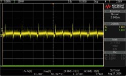
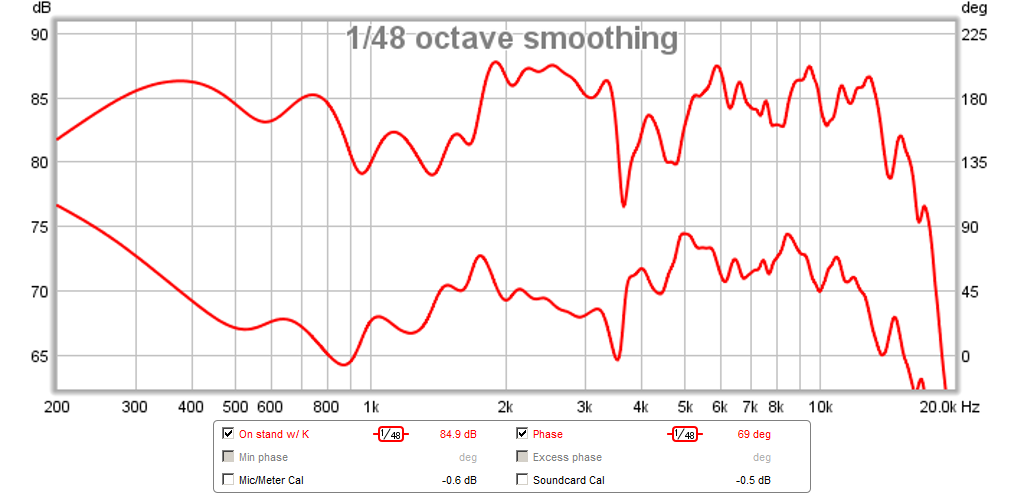
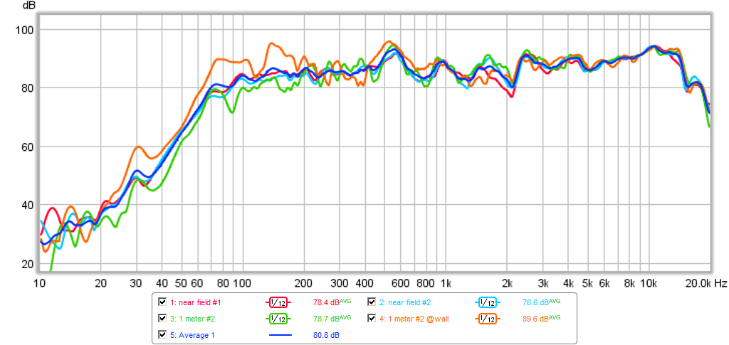
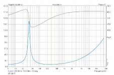
Here is the measured response of the PA130-8 in the 0.53x (at 0.5m with speaker in 29in high stand) - the red trace. Note that scale is 5dB/division and this is gated to 4ms and 1/48th octave averaging. The performance of about +/- 3.5dB is very good for a K aperture and good for many speakers in general:
474642d1427700312-mini-karlsonator-0-53x-dual-tc9fds-0.53x-knator-pa130-8-phase-0.5m.png


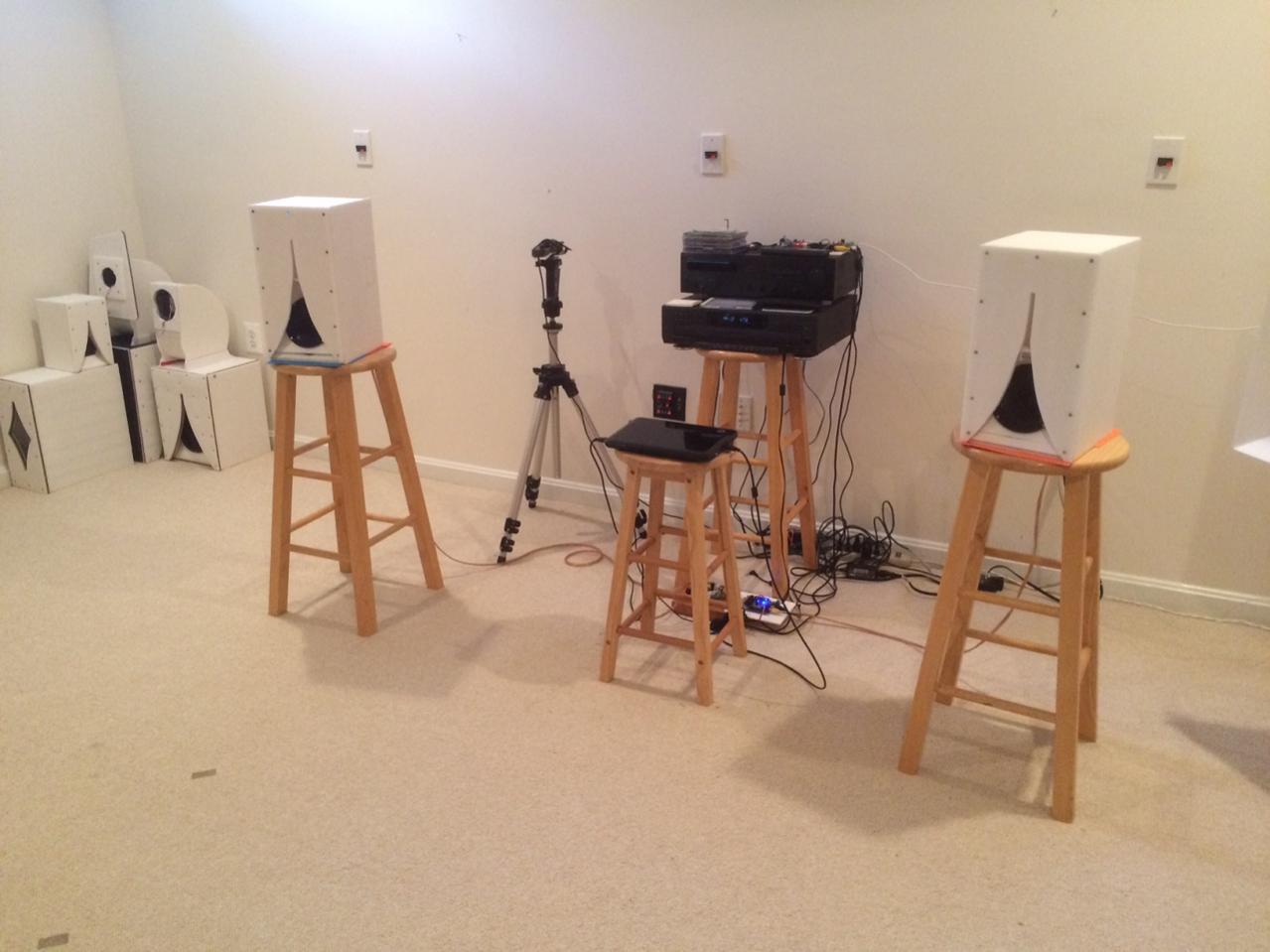
In stereo as a stand-mount speaker the imaging is fantastic and with a wide sweet spot afforded by K aperture:

474781d1427744846-mini-karlsonator-0-53x-dual-tc9fds-foam-core-lab-knator-stereo.jpg


EDIT (12/1/2013): There is a 0.4X single driver version that is only 12 in tall x 6 in wide that works very well. Go to post 160 for details
http://www.diyaudio.com/forums/full...sonator-0-53x-dual-tc9fds-16.html#post3722988

EDIT (1/3/2023): Here is the DXF file for laser cutting a score and fold 0.40X foamcore Karlsonator, file provided generously by member @mudjester.
https://www.diyaudio.com/community/...or-0-53x-with-dual-tc9fds.239338/post-7554841

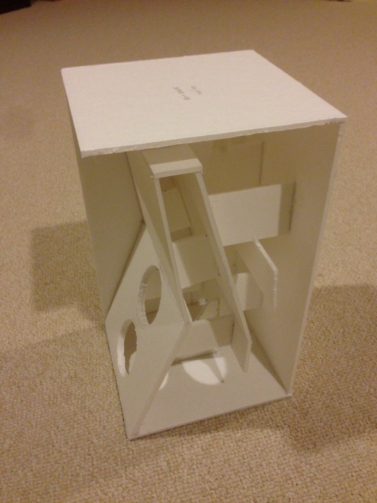
Here is a photo of the 0.4x

385169d1385877585-mini-karlsonator-0-53x-dual-tc9fds-photo-build-03.png


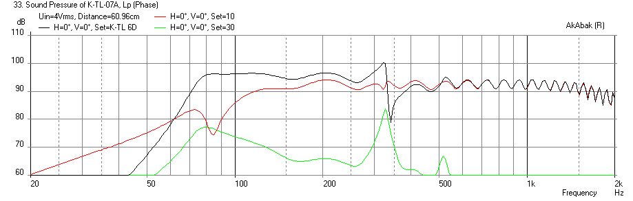
Here is the predicted response of the 0.4x with a single TC9FD with 2 watts power and listening near field at 24 in (on a desk for example) and a wall located 5 ft away.
385369d1385996783-mini-karlsonator-0-53x-dual-tc9fds-karlsonator-0.4x-tc9fd-freq-24in-reflections.png


Edit: Hot off the press! Sept 17, 2014 - 
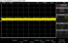
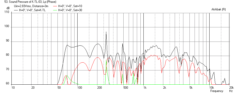
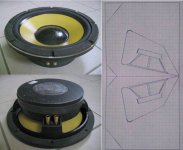
Here is the measured response of the 0.40x with a Faital Pro 3FE25 driver (4ohm):

439061d1411026705-mini-karlsonator-0-53x-dual-tc9fds-karlsonatpr-0.40x-3fe25-avg.png


Here is the sound clip with the 3FE25:
diyAudio

Here is a nice drawing of the 0.4x plans by Bl21de3 (Blaides):
http://www.diyaudio.com/forums/full...sonator-0-53x-dual-tc9fds-56.html#post3880182

Here is the Cut and Fold Razorlab or Ponoko File version of the 0.4x for a smaller Visaton FRS8.
http://www.diyaudio.com/forums/full...onator-0-53x-dual-tc9fds-103.html#post4113372

410245d1396600506-mini-karlsonator-0-53x-dual-tc9fds-karlsonator_04x_print.png


Edit: Sept 18, 2015 - Plans for 0.44x tall x 0.44x deep x 0.55x wide K'nator for FE103SOL or FE103/RS 40-1197: https://plus.google.com/photos/1005...6195254979670171890&oid=100545049816297868412

Here is the post showing details of the build process for a Score & Fold 0.4x:
http://www.diyaudio.com/forums/full...onator-0-53x-dual-tc9fds-115.html#post4139973

Post 198 has a nice CAD drawing of the dual driver 0.53x plans by Tb46.
diyAudio

Edit Mar 8, 2017: Here is a nice plan for a 0.50x & 0.42x wide Karlsonator for a Pluvia 7

http://www.diyaudio.com/forums/atta...or-0-53x-dual-tc9fds-karlsonator-pluvia-7.pdf

http://www.diyaudio.com/forums/atta...onator-pluvia-7-cutting-folding-glue-plan.pdf
----

I started this idea in the Speaker that Kicks Butt thread here:http://www.diyaudio.com/forums/full-range/237948-speaker-kicks-butt-large-spaces-19.html#post3553874 , and found that the speaker I built worked so well, and there has been interest shown by others for plans and construction details that I thought it deserves it own thread. I have to give credit to GregB who designed the Karlsonator (full scale) as this speaker was simply scaled down in size by approximately 0.53X to accomodate the dual drivers on a vertical orientation. The Karlsonator original plan can be found here:
https://lh3.googleusercontent.com/-...ABik/txissf4J4PI/w678-h524-no/Karlsonator.png

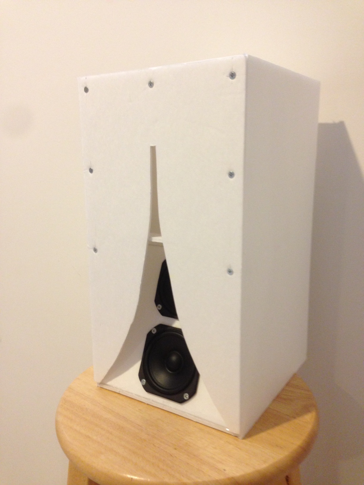
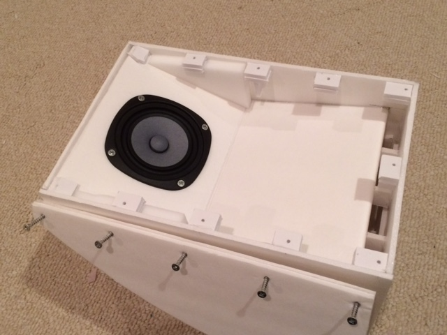
This speaker could be built out of plywood certainly, but as a foam core build, it was very easy to make (about 2 hrs) and is a very cost effective great sounding speaker. If you are familiar with my work, you will notice the recurring commonality: the Vifa TC9FD driver. This is a great sounding inexpensive little driver and I was surprised that it works in this type of enclosure given that it is relatively high Qts. I would not have built it had I not simulated it in AkAbak first (http://www.diyaudio.com/forums/full-range/237948-speaker-kicks-butt-large-spaces-19.html#post3553874)

The initial sim shows a nice punchy bass shelf down to about 70 Hz:
358812d1373293761-speaker-kicks-butt-large-spaces-karlsonator-8x-dual-tc9fd-freq-3m.png


I then proceeded to build it in an evening, and it was quite a fun and easy build that can be done with exactly 2 sheets of $1 foam core board from the dollar store.
359932d1373734918t-speaker-kicks-butt-large-spaces-karlsonator-1s.jpg

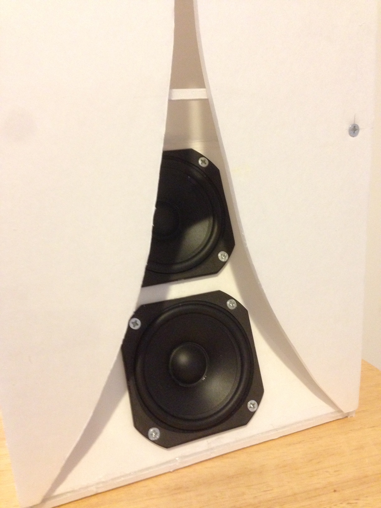
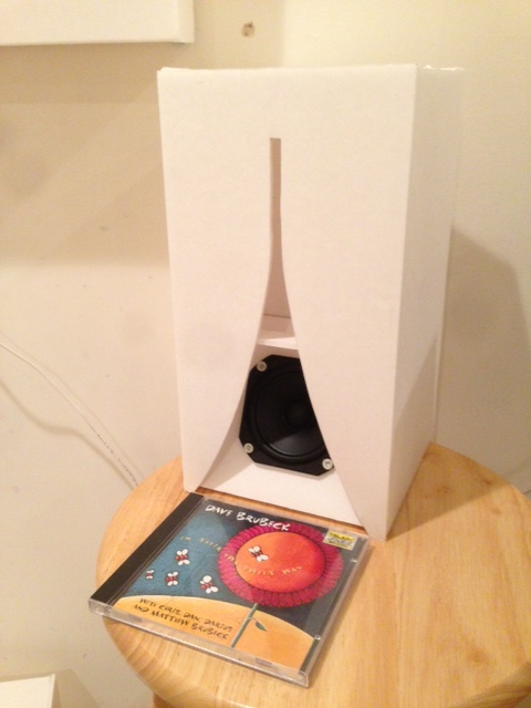
Here is the finished speaker:
359935d1373734918t-speaker-kicks-butt-large-spaces-karlsonator-6s.jpg


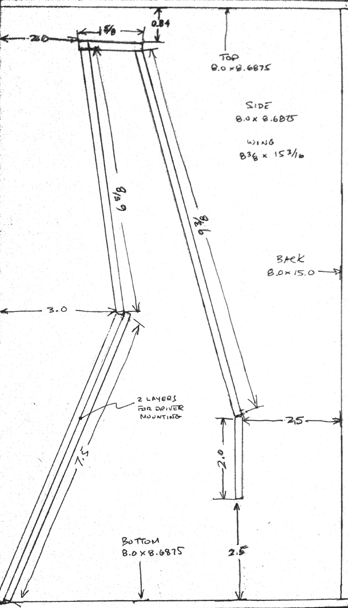
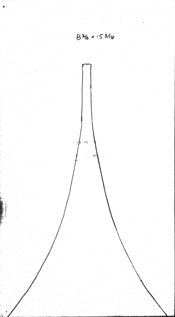
The plan, optimized for standard 20 in x 30 in x 3/16 in thick foam core material looks like this:
360409d1373945528-foam-core-board-speaker-enclosures-karslonator-0.53x-plan-1.png

360410d1373945528-foam-core-board-speaker-enclosures-karslonator-0.53x-plan-2.png


359934d1373734918-speaker-kicks-butt-large-spaces-karlsonator-5s.jpg


And when I plugged it in and turned it on, WOW! Even in pseudo mono (left channel to top driver and right channel to bottom driver) I was just amazed at the clarity, depth, and naturalness of the sound. The bass was tight and punchy, and easy - not strained. The sounds from vocals was just wonderful, and bass guitar and bowed double bass just had a very natural presentation. The other thing I noticed was that the speakers were very efficient (that is quite loud) with very little cone movement compared to some of the other cabinets that these Vifas had been in before. I immediately just loved the rich natural sound. It works very well with classic rock like Dire Straits as well as female vocals, and jazz. So you may wonder how it really sounds, well I recorded some sound clips and zipped them so they can be uploaded here. Check them out and see for yourself, they are recorded with a Zoom H4 with XY mic at 3 meters away and stored on pretty lossy 128 kbit format so that I could fit them into the max file size limit. The full size files sound even more amazing.

I highly recommend this build, as it sounds great, is inexpensive, easy to build, and gives you the unique opportunity to experience what a Karlson type speaker is all about. I would not have gone about doing this had it not been for my extensive modeling and simulation of a Karlson, which led me to see (on paper) the unique capabilities: wide spatial dispersion, high efficiency, natural lifelike sound, punchy bass.

I will continue this thread with a build log of the second speaker box so that I will finally have a stereo pair and I will document the build process for you to follow.

I hope you give it a try - you will be pleasantly surprised, and you will have a unique speaker that can be used for a variety of purposes. It excels as a table radio in pseudo stereo for great background music that fills the room with a rich full lifelike sound.

Below are the sound clips. Enjoy! 🙂

Regards,
X


Edit (7/24/2017) - I forgot to include this link for a nice min Karlsonator with CHN-70:
Improving the CHN-70

509046d1444878618-improving-chn-70-chn70-knator-photo-1.png


Edit (Sept 13, 2017): Bonjonno reports that the 0.40x Mini Karlsonator kicks butt as a studio monitor. See post #2120.

635194d1505316980-mini-karlsonator-0-53x-dual-tc9fds-sanc-mk-0-4-jpg


Edit (Aug 23, 2018): Skylar made some nice 0.53x dual 3FE25-8 plans here:
http://www.diyaudio.com/forums/full...onator-0-53x-dual-tc9fds-286.html#post5523965

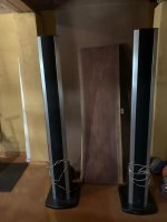
Edit (Dec. 12, 2018): I have figured out how to make the Karlsonators out of wood without sounding boxy. Here is a great example built by Jhofland for me and I finished with boiled linseed oil and hand rubbed wax. Internally lined with melamine foam pads adjacent to driver in rear chamber seems to do the trick. Also added some pads on sidewalls on front chamber and lined backside of aperture with paper faced foamcore. This particular example is fitted with dial 3FE25-16’s.

912196d1610809539-mini-karlsonator-0-53x-dual-tc9fds-5bd64ac4-d2b7-4f39-af60-eea30c1525e2-jpeg


Sketchup plans for above wooden 0.53x by Jhofland here:
Mini Karlsonator (0.53X) with Dual TC9FD's

Tips on how to apply melamine foam pads to break the "wooden box curse" here:
Mini Karlsonator (0.53X) with Dual TC9FD's

Attachments

Dynaco SCA-35 Mod Suggestion?

I have my SCA-35 for couple years. I recapped it right after I got it. Even though, I am not happy about it.
There are couple of issues.
1. It is very picky about 7199 tubes. I tried couple 7199s. Sylvania ones seem to be better than RCA ones. Anyway, my goal is to mod it to use more common tubes like 6BL8. Look at the schematic, R29 is 4.7mega Ohm. Not all 7199s or the substitutes are happy about the "Leak Bias" setup.
2. I don't have a turn table yet, but I still want to keep the phono stage and tone control intact. In case I want to try them in the future. Thus converting it into ST35 is not an option.

PS: Let's focus on the amp section and please leave the phono and the power supply mod out of this discussion.

1736217571884.png


Edit: Final Version #40

Attachments

Tonearm Under-Hang set up measurements

Hi, Over the weekend I read through a very interesting blog on another site about setting your tonearm up for Under-Hang that does not need any anti-skating to be applied
I tried in on with my Temaad 10.5'' arm & yes they are correct. No anti-skating & no mis-tacking of any kind. Very quick & easy to set up it you have enough spare length in your H/Shell slots or you can easily move you arm.

What I noticed from my initial listening is that base output significantly improved & front to back imaging as will. No distortion was heard either on my set up.

So form the info so far posted I made up a setting up chart for arm from 7'' to 16''. try it out you may be very suppressed how good the results are.


Cheers

Under Hang measurements for different Length Arms
Arm length Inch
7
7.5
8
8.5
9
9.5
10
10.5
11
11.5
12
12.5
13
13.5
14
14.5
15
15.5
16
177.8
190.5
203.2
215.9
228.6
241.3
254
266.7
279.4
292.1
304.8
317.5
330.2
342.9
355.6
368.3
381
393.7
406.4
Under Hang mm
-18
-17.41
-16.82
-16.23
-15.64
-15.05
-14.46
-13.87
-13.28
-12.69
-12.1
-11.51
-10.92
-10.33
-9.74
-9.15
-8.56
-7.97
-7.38
0.59​

Oppo's BDP105 - discussions, upgrading, mods...

A new Oppo player is on the way to marked.
This thread is meant to facilitate discussions and ideas changing about BDP105 player, about eventual upgrades, and modifications.

Oppo has come out with only few pictures of the boards of BDP105.
A preliminary examination of the inside pictures it shows that Oppo used a high performing chip op amp for headphone stage. This chip can run up to 2-3W, so is not any problem to drive the most of the headphones. The lowest driving impedance of this op amp is 8 ohm. One can see the placement of this stage on the analogue board here by. It looks to me that the headphone op amp is DC coupled to the output (through resistors)... I`m almost sure now that all the other outputs of the BDP105 are AC coupled. It seems that is planted a large capacitor on the signal output path on each channel! This surprising me very much, and I think is very unfortunate...

It seems to me that the DAC chip itself is used in a different way than in the earlier model (95). A short clarification about the ESS9018 DAC chip: this chip have 8 independent DAC channels inside. Those channels can be connected (hardware) together (2, 4, 6, 8) When all the 8 channels are connected in parallel (for only one stereo channel), one have the max accuracy of the resulting signal. 8 DACs working together and output the same signal (one may use two ESS9018 to have a LR stereo in such case). In stereo configuration of one DAC, are used 4 + 4 channels connected together for max accuracy. Multichannel configuration use all the 8 channels independently.
In the BDP 95 model, the stereo output were obtained from 4 + 4 channels (4 channels connected together). This assured max accuracy for the stereo signal in BDP95 model. In the upcoming BDP105 it seems that Oppo used a configuration for ESS9018 which assure 2+2 channels for balanced/unbalanced output, and 2+2 channels for headphone output. I`m not very sure about the allocation is strictly in this way, but is very sure to me that the Sabre chip is hardware divided between RCA/XLR output and headphone output.

Personally I`m quite critic to this design. I should want that one could have the possibility to use 4+4 channels of the chip for both (switching) normal out and headphone out. This way could assure the max accuracy in both cases. When one use the headphone is no any reason to have half part of the DAC chip hardware dedicated to another output which is not in use, and opposite. This judgement is made as a consequence of what is to be seen in the high resolution inside picture of 105 model. Oppo are welcome to correct me if I have seen wrong in the picture, or to precise more on this aspect...

It seems that this player model have a better distribution of the analogue power supplies and regulators on the boards. Having two dedicated outputs from the toroid transformer it make the PSUs more efficient and it assure less heat dissipation inside the enclosure. This design it were already a must for the 95 model, and it looks like it is implemented now in 105 model.

Esp32_DSP

Hello DIY Audio enthusiasts,

I am excited to share my latest project: ESP32_DSP. It is a digital signal processing solution built around the powerful ESP32 microcontroller, designed for audio enthusiasts who want to explore flexible and affordable audio filtering.

This project integrates a DIR9001 (digital audio receiver) for input, an ESP32 for real-time DSP processing, and a TDA1387 DAC for output. It supports a variety of filters such as low pass, high pass, band pass, notch, peak, low pass, and high pass, offering great flexibility for various audio applications.

While I am confident in the design and functionality, I would like to ask the professionals and experienced members of this community: Is this approach suitable for achieving high-quality audio performance, or will ready-made DSP boards from Aliexpress do a better job?

I would love to hear your suggestions, ideas, and ideas for improvement. Whether you're a seasoned audio DIYer or just starting out, feel free to share your thoughts and questions.

Thank you and I look forward to learning from your insights!

https://github.com/Kristian8606/ESP32_DSP/tree/main

2-Way with only 2 Inductors!

Don't try this at home, kids. Or do, but make sure you get really high wattage resistors. 😀

In another thread someone asked why you can't just design a crossover using 2 caps. One in series and one in parallel. This follows the same idea. Well, you can if you add resistors. I'm not responsible for any fires caused. 😉

Of course, this is purely an academic exercise, with apparently no practical value, but who knows.

1737682445689.png
  • Like
Reactions: stv

AC internal wiring

Hi all,

I am adding a few controls to a slave power amplifier that will be used as a subwoofer amp. I have added a Powercon in, RCA in, Speakon Out, on of switch, volume pot (passive). I will experiment with an active small chip based pre amp (5534 Op amp).

My question is how careful should I be with shielding AC internally, I will twist the L,N where they run in parallel but I will be feeding AC to the main power transformer of the power amp, a small 12V DC board that will drive the quiet fan and potentially a small pre amp. space is limited and I just wanted to check om best practice and advice omn the principles of wiring 230V AC internally (It will be chassis earthed)

I could add some braid and or foil then heat shrink in a few places if necessary etc

t.amp Proline 3000 - Looking for images to help rewiring

1692858662754.jpg


I recenlty bought a used t.amp Proline 3000 amplifier. The previous owner had unplugged all the wires between the transformer and the cap-pcb. I'm now looking for the information to help me reconnect the unplugged wires. I contacted Thomann but the could not share any documents. Also found this thread from this forum with a few diagrams but these did not contain enough information.

The information which I'm looking for is:
1) How to connect the wires coming FROM the transformer to the CAP-PCB.
2) How to connect the wires coming FROM the amplifier modules to the CAP-PCB.

I would be grateful If anyone here could take a few detailed images from under the hood of their Proline 3000.

CAP-PCB

cap_pcb_connectors.jpg


The pins on the cap-pcb are (in the images I have defined the pin numbers myself):

Pin # / Label

01 / AC Input
02 / AC Input
03 / AC Input
04 / AC Input
05 / +VCC-H
06 / +VCC-H
07 / +VCC-L
08 / +VCC-L
09 / GND
10 / GND
11 / GND
12 / -VCC-L
13 / -VCC-L
14 / -VCC-H
15 / -VCC-H
16 / V~L
17 / V~L
18 / V~H
19 / V~H
20 / Multipin (2pins)
21 / Multipin (6pins)
22 / Multipin (5pins)

TRANSFORMER

20230824_201234_crop.jpg


from Transformer to CAP-PCB

Brown
Red
Red
Yellow
Yellow
Blue
Blue
Black


from AMP modules to CAP-PCB

Red
Red
Orange
Orange
Green
Green
Blue
Blue
Black
Black
Multipin (5pin) Green,Green,Brown,Brown,Black

Help to understand "current drive"

I am reading Esa Meriläinens book "current driving of loudspeakers" . He uses voltage controlled current sources (transconductance amps) to drive the loudspeakers. If he is right with the idea that this is the physically correct operation method, this could probably gain lower distortion in the range of 3 to 26dB (depending on the speakers used an the frequency).
But all amplifiers you can buy are voltage controlled voltage sources - one has to build the voltage controlled current source by doing it yourself. So my question here is: is this worth the effort? It is not only the amp that is different, the way to build the speaker has also to be adapted to the other way of driving the speaker....

for example: if you build your speaker with Qt=0,7 you know that the level is down 3dB at the spakers resonance - when driven with a voltage source.
If driven with a current source it is different as the current source draws its current without regard to the speakers impedance - and therefore the impedance curve shows up on the speakers level curve. The consequence is,that the speaker is louder at its resonance and gets louder as the frequency rises - following the impedance-curve.

If one will compare both ways to drive a speaker the speakers equalisation has to be done individually with respect to the driving method. Assuming the equalisation is done in a way that both types measure the same in sound pressure level.... : Is a current driven speaker delivering a better sound quality? Or is it just different / the same as driven in a conventional way?

All hints for building a high quality (state of the art) current amp are welcome, and so are measurements on real speakers that show the difference between the driving methods.

Bernd

Long time lurker first time poster...

Heya, been tinkering with audio DIY stuff for a few years now, and have found this place (amoung others) very useful and helpful in my journey ... so thanks! I finally decided to join as I am warming up to get out of my depth on a few projects, and there's no one better to ask for advice than people that have already done what (or something similar to what) you are wanting/planning to do. Cheers :cheerful:
  • Like
Reactions: birdbox

Hello from The Philippines

Hi everyone, I joined this forum years ago just not active, I am now posting as I want to learn more of DIY Audio what's new in 2025, re-ignite the hobby of hardware and software including DIY building of mechanical fiber glass or aluminum casing. My passion is to build something easy, affordable fast to do and fun to do, currenlty I am imagining a class-A or class-D amplifier with its own casing and a good Human Machine Interface Nextion touch screen LCD, I would like my amplifier talk to me to have a dedicated displaying with my own MMI (man machine interface),, I think a DIY casing and HMI front panel makes the amplifier nicer and enjoyable to use, I love small form factor amplifier for personal use. Probably someone already implement the idea, or someone can walk with me and make my personal project into something educational, shareware and courseware. I love the concept of DIY but I am getting into DIT now (Do It together). I also fond of PC base Audio test equipment, like virtual oscilloscope.

For Sale JBL 4670D

You’ll need a transit size van at the very least.

There are dings and scratches as you may well expect given that they’ve come from a commercial environment.

I’ve listed them on here as I’ve seen quite a few threads where people are using these at home .

I can’t seem to add the photos at the moment, I’ll try again later


£700 the pair
collection from MK5 ( UK )
  • Like
Reactions: JRKO

New RCF Bass drivers LN16S400/LN19S400

Heya.
RCF recently released new high excursion drivers LN16S400 and LN19S400.
To me it looks they did right with the suspension what B&C didn't, but oh well 4" CCAW voice coil doesn't allow it to sit in our "sick top end" class. That is unfortunate.
Anyone planning on using these in their project? I wonder if one can push these into smaller volumes (150l for 19"). These need excursion to not burn...

Drip Electronics Dual 176 PCBs

Has anyone had experience or success with building a 176 compressor clone using the PCBs from Drip Electronics? I got well into the project but stalled when I needed some questions answered by Drip and Gregory there went silent. A beautiful design and nifty PCBs, but some uncertainty about some of the capacitor values and circuit alternatives on the PCBs has me stymied.

-Jon

Vented/open midrange

Does having a vented / open midrange driver enclosure (3 way design) have any advantages over sealed midrange. Sealed is the "obvious choice" because of GD, however I plan to have it passively crossed at 400 and 2,5k and the GD is in sealed enclosure territory within 400 hz when modeled in software. The speaker is going to be Wilson Sabrina sized and they have what looks like a port for the midrange at the top. So what's it for? Does it improve sound quality? Does it flatten the impedance curve? I suppose it's not used for the 3dB gain.

For Sale NOIR headphone amplifier fully assembled

SOLD

For sale is a NOIR HEADPHONE AMPLIFIER fully assembled. It comes assembled in the official diyaudio store chassis (https://diyaudiostore.com/collectio...ir-headphone-amplifier?variant=30182425526306).

I am asking $140 + shipping for the fully assembled and tested headphone amp. Shipping within the US via USPS Priority Mail. Would prefer to sell within US as the international shipping is too expensive these days.


Regards,
Subbu

Attachments

  • PHOTO-2023-07-10-17-09-35 2.jpg
    PHOTO-2023-07-10-17-09-35 2.jpg
    429.1 KB · Views: 311
  • PHOTO-2023-07-10-17-09-35 3.jpg
    PHOTO-2023-07-10-17-09-35 3.jpg
    97.4 KB · Views: 303
  • PHOTO-2023-07-10-17-09-35 4.jpg
    PHOTO-2023-07-10-17-09-35 4.jpg
    121.5 KB · Views: 224
  • PHOTO-2023-07-10-17-09-35 5.jpg
    PHOTO-2023-07-10-17-09-35 5.jpg
    122.8 KB · Views: 315

The Official HORNLESS Compression Driver Thread

(UPDATE 17th December 2016 @ end of this post)


I have heard about (very) few people playing with CD in hornless config, but i had to try it by myself.

Well, i did.

I got my hand on two pairs of CD:

760NEO (3'' voice coil + 2'' exit)
950PB w/ Beryllium (4'' voice coil + 2'' exit)

For the sake of testing, the ''hornless plate'' is simply a plate made of 15mm thick bamboo. I'm planning to have something even ''more hornless'' with a non-magnetic steel plate (316 stainless).

So, the big question: DOES IT WORK ?

Short answer: yes.

Ok, but does it work GOOD: ?

So far, I LOVE IT.

Check the images....

That's the 950, crossover points 4120hz... 480hz (!)
Also check the EQ: instead of boosting the lower-end, i reduced what i consider the peak of the driver (-13db seems a lot, but... it works flawlessly)

Note: it shows two dips around 560hz and 1400hz that i didnt took care yet, but the important thing is i still have energy at the crossing point of 480hz, which is nothing short of amazing. Since i play at moderate volume (domestic, not stadium needs here) i don't ear or feel any problem whatsover (distortion, xmax limit, etc..)

An externally hosted image should be here but it was not working when we last tested it.

An externally hosted image should be here but it was not working when we last tested it.

An externally hosted image should be here but it was not working when we last tested it.


--------------

(update 17th december)

Quick notes about my impressions on both Compression Drivers in general and Hornless specifically:

PROs
.: Ultra detailed mid, you don't hear that kind of resolution, energy and micro-dynamics from any cone between 400hz and about 1khz.
.: Blend very nicely with ribbon tweeters
.: Hornless config delivers a great airy, open, 3D-like feeling and sonic presentation.
.: High SPL output potential
.: CD drivers like the Radian 950PB and some BMS can have low crossover points, such as 250hz
.: Made for very demanding PA, they permit agressive EQ corrections and lower xover point in domestic environnement.
.: No need for separate enclosure
.: Hornless = simple, compact
.: Changeable diaphragm in case you push one too far...

CONS
.: Most high quality CDs are expensive, especially the neodymium versions
.: Not because it's hornless they lose their high efficiency... and the noise that comes with it, if you have poor electronics...
.: Requires active config for optimal results (massive gain adjustments, EQ, steep xover slopes, etc..)
.: Could work in 2-way (CAST) but optimal results in 3-way or 4-way
.: I don't think the CD technology in general has much to offer passed 4khz in terms on subjective quality, even from the smaller ones. AMT and Ribbons are superior in the last 2 octaves, IMO.

Valve Itch phono

After my NJFET phono, the shunt Mosfet LV and HV psus, I felt too deeply buried in sand. Got an itch. The valve itch. :clown: 
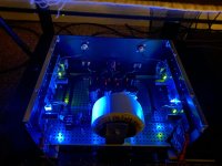
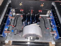
Had to mess with glass again.
Having the Simplistic NJFET and the Steve Bench 12AY7 & 6DJ8 cascode already, both on Mosfet shunts of mine, I knew it would be a tough call. Comparisons would come inevitably. So I thought to compare along testing and tweaking phases so to make something that has some sonic merit to stand there. To have something compelling to tell in its own tone way.
The design had to use preferably cheap and available but very silent tubes. Had 6N2PEV Russian tubes that I wanted to test. I liked their characteristics. Also 6N8 NOS Soviet black anode 6SN7 equivalents. I want the most gain there is available on first stage, I don't want extra resistors there, want good PSRR, and lower gain at second stage. Also low impedance Riaa I prefer, so some good drive is needed. Two mu follower stages with passive Riaa between, seemed appealing for my concepts. I have seen the Phono Dude doing that too, have never had one, but it was good to know it already works as phono with some acclaim. Put it together on the simulator, tweaked this and that, seemed nice. I decided not to look for how low THD, as long as it would be predominantly second. Wanted some triode like tone this time since the NJFET and Bench do the monitor style already.
Good DIYer mate Mikvous liked the idea and decided to make one in some spare boxes that used to house a Thorsten phono, so we can test and tweak. It took us about 2 weeks so to decide its what we wanted.
The noise floor is amazingly low for 61dB gain of step up and valve phono. Pitch black background. The THD is 0.2% 2nd, and the Riaa curve is identical to the NJFET Riaa. No metal shield caps on the input valves for such a low noise floor, and we can happily knock em on their glass while the volume is set loud and hear nothing. The sound is great. Lush but has it all. Best valve phono we ever had bar none. And we had tested about 7 DIY ones.😎

Attachments

  • Itching.JPG
    Itching.JPG
    136.5 KB · Views: 5,135
  • DSCF1713.JPG
    DSCF1713.JPG
    87 KB · Views: 4,999

Refurbish crossover B&W DM640

Hi there,

I have my DM640's for a long long time by now. A few years back I replaced the ferrofluid ad put them on spikes. Other than that, they are as they came from the factory.

They are almost 30 years old by now and I thought it to be a good time to refurbish the crossovers.

The new parts will be a fair bit larger than what's in there now, so the idea is to build new crossovers from scratch.

I'm no audio engineer, so the idea was to keep the B&W design and just build with better parts.

This is the schematic from B&W (I corrected a typo in the schematic in the technical manual, where C3 was called C2):
DM640_corrected.png


Default values of components:
C1 85 uF
C2 85 uF
C3 16 uF
C4 7 uF
C5 16 uF

R1 8R2
R2 8R2
R3 1R0

L1 5 mH
L2 0.3 mH
L3 2.5 mH
L4 0.15 mH

New parts I'd though to be a good replacement:

Internal wiring will be replaced with 4mm2 copper wiring for the woofers and 2.5mm2 copper wiring for the mid-range driver and tweeter. I want to twist the wires and solder them directly to the drivers instead of using spades like stock. The only driver that won't be directly soldered is the tweeter, since they have sockets that would be hard to solder and I don't want to hack them up.

C1
To get to the 85 uF without breaking the bank I wanted to use the following caps. This would mean a 68 uF bipolar electrolytic with the remaining 17 uF from polycaps. From what I've read, the audible effects of electrolytic are less of a problem in the low end of the audio spectrum and this cap being in parallel would also make it less crytical.

My selection of caps that will be wired in parallel:
Mundorf ECap plain 68 uF
Jantzen Cross-cap 16 uF
Jantzen Cross-cap 1 UF

C2
This cap is in series in the crossover for the mid-range driver. I wanted to use poly caps for this.
My selection of caps, will be wired in parallel:
Jantzen Cross-cap 82 uF
Jantzen Cross-cap 3 uF

C3
This cap would be less critical, since it is in parallel. Since the cross-caps don't cost the bank, I chose to also use a poly cap for this one.
Jantzen Cross-cap 16 uF

C4
Cap in series for the tweeter, all poly caps to get to 7 uF with a small 0.1 uF bypass cap from the superior series.
Jantzen Cross cap 3 uF
Jantzen Cross cap 1 uF
Jantzen Superior-Z 0.1 uF as bypass cap

C5
Same reasoning as behind the C4
Jantzen Cross-cap 16 uF
Jantzen Superior-Z 0.1 uF as bypass cap

R1 and R2
Both Jantzen Superes 8,2 ohm, 10W

R3
Jantzen Superes 1 ohm, 10W

For the inductors I wanted to use air core inductors all arround. I know copper foil would be even better, but I think it would be overkill for these oldies, air core will be a nice step up.

L1 Jantzen 5 mH air core 13 AWG
L2 Jantzen 0.3 mH air core 18 AWG
L3 Jantzen 2.5 mH air core 18 AWG
L4 Jantzen 0.15 mH air core 18 AWG

What I'm conscerned about is the difference in resistance between the old inductors and the new. I have no idea how this will effect the crossoverpoints and / or slopes and how to correct the values of the other components to compensate for this or if this is even needed at all.

Hope someone can advise.

fr_4677.jpg

Polystyrene film capacitor low temperature tolerance (during shipping)

Hello,

I need some polystyrene film capacitors shipped to me. The problem is the temperature outside currently hovers around -35° with peaks down to -40°C. I can't find definitive information on this type of caps's tolerance to such low temps but there are tempco graphs going down to -40°C. But can the caps actually sustain, without damage, that temperature during a long-ish shipping route (the seller is overseas), or I'd better wait until spring time.

Thanks in advance

Choices for a speaker with reasonable WAF?

All,

Looking after a speaker system of decent quality for a modest apartment (about 5 x 7 meters), but accepted by the partner. So, a not-too-ugly form and modest dimensions. My own requirements are in the direction of little distortion and good imaging, moderate listening levels.

I'd like to build it myself, having enough experience as a furniture maker, I probably can manage to make cabinets, but it would be my first speaker build in about 50 years. The last one was a Wharfedale kit with the drivers from the Dovedale 3 model, so about the early 1970s. I read that a first attempt would better be to take a proven design -- I have come across a few that are tempting, but I'm still unsure about what to select. Unfortunatey, one cannot go out for listening tests in the DIY area.

I think about Troels Gravesen's Discovery-12W with a (too) expensive tweeter or xrk971's FAST/WAW monitor with the 10F/8424 and the RS225-8 drivers. I have also been given (really!) a set of four Decca Kelly Ribbons (DK130) which I could combine with a Mark Audio Alpair 12W (as advised here), but then the cabinets' recommended size quickly becomes an issue. Ideally, I should have not more that 50-60 cm centimeters of height. As it is a first attempt , I am thinking about a budget of +/- 400/500 euro for the drivers, so there's not too much lost.

Other ideas are welcome! My music preferences are more towards jazz combos, vocal music and a lot of classical/preclassical music. In my man attic, I'm using Quad ESL57 speakers, just to make that clear.

As there is a Bang& Olufsen showroom just around the corner, my spouse has remarked the Beolab-8 speaker and she likes its appearance a lot, though not the price tag. So I could attempt something similar to this (design can be better, I could 3D print look-alike aluminium or bronze parts):


SpeakerBox.png


But adding this kind of cosmetics may be detrimental to the sound. A speaker grille or front isn't always for the best, so it seems. OTOH, there are grandchildren (and cats and dogs) which may be tempted by those cones that bounce when you press them, so some covering could be beneficial. What are the ideas about wooden strips as a grille?

Your comments are welcome !

Cheers,

Jacques

  • Like
Reactions: camplo

FaitalPro 3FE22 projects (nice little full range driver!)

I started this thread to document my projects with this little driver. I put it into the multiway forum, since most (if not all) projects cannot be used really as standalone speakers. I ordered 26 units on sale, so now I have 36 pieces in total.

It all started with the 34c9 project: My 34c9 (omnidirectional full range with 3FE22) build

I use 4 units as midranges for my AMT Synergy: ESS AMT-1 in my projects

Eliminating an input DC blocking cap

I'm modding a power amp with a schematics attached to improve the sound quality. It has speaker DC voltage protection, so I'm looking for options on eliminating an input DC blocking cap C5025.

DC voltage on the positive lead of C5025 is a few mV, but on the negative lead is -0.1V w.r.t. ground. If I short C5025, I'm getting +0.1V DC on the speaker output instead of 0V DC.

Are there ways to properly DC bias this amp after eliminating an input DC blocking cap C5025 without re-designing its schematic much?

Attachments

  • Power_Amp_Schema.PNG
    Power_Amp_Schema.PNG
    285.3 KB · Views: 339

use of resonating membranes inside the enclosures

Hi everyone,
I am exploring alternatives to traditional sound-absorbing materials (foams, fibers, and pyramidal diffusers) for the treatment of reflections, standing waves, and harmonics inside loudspeakers. In particular, I am focusing on the use of thin membranes, placed on the internal walls, to absorb specific unwanted frequencies.
The idea is to use flexible panels composed of a thin film coupled with layers of neoprene or rubber to create membrane resonators and reduce problems in the low frequencies. Some points I would like to discuss with you:

1️) Materials and Structure: What materials have you successfully tested for these applications? Are there particular combinations that improve the effectiveness of absorption?

2️) Positioning: Is it more effective to place the membranes on all the internal walls or just on some strategic areas? Are rigid panels better or with a minimum of flexibility?

3️) Thickness and Mass: How does the mass of the membrane affect the resonance frequency? For example, do two membranes with different areas but the same mass behave differently?

4️) Overlap and Spacing: Is it possible to overlap multiple membranes leaving an air gap between them? If so, is it useful to tune them to slightly different frequencies for a wider action?

5️) Alternatives to Helmholtz Resonators: In which cases can membranes replace or integrate Helmholtz resonators?

Does anyone have experience or practical tests on this technique? I would like to collect ideas, experiments and maybe compare some simulations. Thanks to anyone who wants to share their know-how!

Hello from Sweden

Hello all

I’ve been working on audio electronics for some time now, with a focus on repairing and restoring vintage amplifiers. Currently I’m deep into troubleshooting and restoring a Denon POA-6600 amplifier, replacing various components and checking circuit functionality. Looking forward to connecting and exchanging ideas with fellow audio enthusiasts.✌️
  • Like
Reactions: Fuling

KSC2690 / KSA1220 (8 sets) for sale

For sale 2 sets KSA2690A-Y / KSA1220-Y

1 sets = 25 pcs. or more KSC2690A-Y + 25 pcs.or more KSA1220-Y )

Minimal order: 1 set

KSC2690A-Y NPN Mfg. ONSEMI 160V 1.2A TO126 isolated
KSC2690AY x 25 = 8,62 euro ( about 0,34 - 0,35 euro / 1pc.

KSA1220-Y PNP Mfg. FAIRCHILD 120V 1.2A TO126 isolated
KSA1220YSTU x 25 pcs. = 11 euro ( about 0,44 euro / 1 pc.
KSA1220 ( DISCONTINUED PART )

1 sets = 19,62 euro

Shipping cost: registered priority ( box + antistatic bags ) = 6,50 euro
below original photo. / datasheet

Attachments

  • KSC2690 KSA1220 sm.jpg
    KSC2690 KSA1220 sm.jpg
    64.5 KB · Views: 198
  • KSC2690A.pdf
    KSC2690A.pdf
    152.9 KB · Views: 116

Stereo output shorted on one channel.

Working presently on a Telefunken Magnetophon m3002 r2r. Anybody out there familiar with the audio output amps in these? The amplifier board fried the output transistors, so I can't power up until I locate the issue. One item showed up on resistance checks, R306 on the left channel checked at about 800 ohms. The identical resister on the 'good' right channel checked dead on at 6.8k. Circled on schematic. P90 Any thoughts?

Attachments

  • 20250117_122309.jpg
    20250117_122309.jpg
    636.6 KB · Views: 76
  • 20250125_200834.jpg
    20250125_200834.jpg
    523.3 KB · Views: 73

Plate choke and plate load resistor together ? How?

Hi!
Anyone can explain to me what is it about?

"I was talking about a resistor ACROSS the inductor! so the low DCR of the inductor will be used!!!

THAT shunting offers a real need, sets the impedance of the inductor to its value

Using a choke (inductor) as plate load and shunting it with a plate load resistor, will offer more plate voltage to the tube used. due to the plate load resistor will be the load impedance, not the DCR,

The choke will be maybe 50 ohms or so......"

Thank you 🙏

SP168HT-SP320HT - MONACOR's most ultimate solution for Bass Drivers from the 80s

I am looking for the manufacturer of the no longer available and obsolete speaker models from follow MONARCH models:
1) SP-168HT
2) SP-210HT
3) SP-260HT
4) SP-320HT

Very special by all models was the surround rubber material
with extremely low friction losses (high Qms values) and
extremely low temperature dependence at the same time.
Therefore one get very clean and tight bass reproduction by this models

Successors in this kind are very hard to find. For this reason the next step is to find out the manufacturer.
Who knows this?
In the attachment you will find various pics.

Attachments

  • Monarch SP-168HT- order code 10.1790 front.jpg
    Monarch SP-168HT- order code 10.1790 front.jpg
    32.8 KB · Views: 516
  • Monarch SP-168HT- order code 10.1790 front-II.jpg
    Monarch SP-168HT- order code 10.1790 front-II.jpg
    68 KB · Views: 555
  • Monarch SP-168HT- order code 10.1790 impedanz.jpg
    Monarch SP-168HT- order code 10.1790 impedanz.jpg
    34.8 KB · Views: 555
  • Monarch SP-168HT- order code 10.1790 rear.jpg
    Monarch SP-168HT- order code 10.1790 rear.jpg
    46.2 KB · Views: 620
  • Monarch SP-210HT- order code 10.1780 rear.jpg
    Monarch SP-210HT- order code 10.1780 rear.jpg
    123.6 KB · Views: 642
  • Monarch SP-210HT- order code 10.1780 terminal.jpg
    Monarch SP-210HT- order code 10.1780 terminal.jpg
    102.4 KB · Views: 389
  • Monarch SP-260HT- order code 10.1770 front.pdf
    Monarch SP-260HT- order code 10.1770 front.pdf
    39.5 KB · Views: 180
  • Monarch SP-260HT- order code 10.1770 rear.pdf
    Monarch SP-260HT- order code 10.1770 rear.pdf
    46.3 KB · Views: 173
  • Monarch SP-320HT- order code 10.1760.jpg
    Monarch SP-320HT- order code 10.1760.jpg
    103.9 KB · Views: 405
  • Monarch SP-210HT- order code 10.1780 front-II.jpg
    Monarch SP-210HT- order code 10.1780 front-II.jpg
    86.7 KB · Views: 413

Hello from Portugal

Hello audio lovers,

I am Martin, a french raised german freshly moved to Portugal (if that makes any sense).
I have a furniture design background and love to DIY anything (electric repairs, woodwork, simple electronic...).

My interest is around speakers (something quite new) and a little bit for amps.
I mainly listen to jazz, 70's funk / Jazz funk & soul music, preferably on vinyl. With age, leaning more towards Jazz (Clifford Brown, Dizzie Gillespie, Max Roach, Gil Evans...) we enjoy listening to with my wife.
Our system as of now is an old Revox 750 B amp and KEF Q300 bookshelf speakers (with a moded crossover and damping).
Vinyl TT is a simple Audiotechnica with a nice eliptic Jico stylus on a Shure VM 2 head.

My next project would be to build a folded Voigt pipe transmission line pair of speakers with a simple fullrange driver (Visation B100 or Fostex or Markaudio Pluvia).
My KEFs are quite pleasant but they really lack some good bass.

I started fiddling around with Hornresp so I am about to post some questions soon to get some help!

Please be indulgent as I am really not a sound engineer nor an electronics expert!
🙂

Cheers, M.

Bolander Graebner Radia 520i Speakers with Center Channel

Excellent condition BG Radia 520i speakers with the rare and awesome BG-50 ribbons. Moved to electrostatics. These are awesome but my Acoustat 6600's are a cut above. These would make an awesome system with some ob subs. $1500. I have the center channel speaker as well. PM with questions. Located in southwestern Wisconsin.

Attachments

  • bg 2.jpg
    bg 2.jpg
    391.6 KB · Views: 93
  • bg-50 1.jpg
    bg-50 1.jpg
    873.4 KB · Views: 88

Any (very) inexpensive pre-amps I could use for a ukulele?

It's been a while since I visited, and I still know next-to-nothing about amps, and I'm hoping someone could point me in the right direction...

I need a pre-amp for a passive pick up on my ukulele, and I have next to no budget. I vaguely remember reading about some very low-cost headphone amps that were built around Altoids tins - I think it was a penguin amp.

Can anyone offer me some guidance on a very low cost, pre-built option - if any such thing exists!

Thanks a lot.

JL Audio 300/4 Q510 Function

I have a JL 300/4 (v1 I believe) that had an issue. It had no output on the front right output. Other 3 channels worked just fine. All 3 LED's on all 4 driver boards lit up green. The only thing that looked abnormally hot under a thermal camera to me was Q510. I have seen it mentioned in other threads as a potential problem, but what is the purpose of this particular IRFZ44N?

After a bunch of other checks and looking through a couple other threads on this amp and after cleaning and reseating the predriver board, all the channels worked. So I'm going assume that this was the only issue. This was my first time repairing one of the old slash amps, so I was not really sure what to expect. I did go through and resolder the 47k larger resistors on all the driver boards like some people had found to be problematic. I also reset the bias of all channels to 4mV (they were all close already between 3.5 and 4.5mV to begin with). The amp idles at about 2.2amps on 13.4V supply, which seems kinda high but I have no reason to think it is wrong. A bunch of the discrete transistors on the drive cards get up around 80C also, but seeing how they were ALL doing that and I had good sound/voltages, I assume that is just normal. Do all of these things sound correct on these older JL's?

Bottlehead gear

Hey,
As you may have noticed I’ve been trying to sell alot of stuff that I just no longer use. Some things were just bought, used for a bit and then moved along. Other stuff I built myself and used for quite awhile, and enjoyed thoroughly. Such is the case with the Bottlehead gear you see here: a pair of Paramount monoblocks, configured as 300B and an extended Foreplay 3 preamp configured with Psvane CV 181-T (6SN7 equivalent) The power inlet for all 3 components has been moved to the back panel along with all input and output RCA connections. I’m interested in selling these but am unsure how to price. So this is just me testing the waters, so to say. More pics and details for those interested.

Attachments

  • IMG_3987.jpeg
    IMG_3987.jpeg
    951.9 KB · Views: 118
  • IMG_3986.jpeg
    IMG_3986.jpeg
    945.8 KB · Views: 116
  • IMG_3985.jpeg
    IMG_3985.jpeg
    930.1 KB · Views: 109
  • IMG_3984.jpeg
    IMG_3984.jpeg
    893.4 KB · Views: 112

Hello from the Blackforest Germany!

I have been following this Forum for more 3 years now and I’ve already built a lot of stuff from the DIYaudiostore. I never posted anything, but read throuch a lot of threads. I really really love this forum and it has become one of my favourite places in the internet!
So far I’ve built ACP+, Aleph J, Pearl 2, Korg B1, Iron Pre and hopefully much more will follow.
My speakers are Tannoy Cheviot HPD’s and JBL 4333a’s that I am restoring right now. Also I am building a dac at the moment Lampucera, and I am a Vinyl collector.
Hope to talk to you on the Forum soon!
All the best
Tobias

tempImageRWxeEr.gif

For Sale Military TV-2 C/U tube tester by La Pointe Industries

SOLD

Asking $400 plus shipping

Military style TV-2 C/U tube tester made by La Pointe Industries Inc. These were made by many companies for the military, most famously Hickok.

Quite intricate and somewhat complicated tester. It is easy to use if you follow the directions for general use and for the particular tube being tested.

The unit tests in percent quality, not microohmos, just as the military TV-7 types do.

I purchased it 12 years ago just after it was modified and calibrated. It has a digital replacement for the “percent quality” meter and a milliameter in place of the plate voltage meter. Beyond that it has had the old electrolytic cans replaced with modern electrolytics.

The unit is in overall very good condition. All parts function. It has a spare 83 rectifier tube in place, and I am also including a solid state 83 rectifier replacement if you would like to use that and recalibrate for it’s use.

It has always tested comparably to other Hickok and computerized testers I have had in the past. I did test a 12au7 and it is testing the same as it did a number of years ago.

The sale includes the tester in case, a few extra socket savers, the 83 solid state rectifier substitute, 3 different tube data books/photocopies, copy of the maintenance manual, an analog plate volt meter if you wish to replace the milliameter, schematics, and a CD with these data sheets and a few other odds and ends.

I prefer a local sale as the cost to ship looks to be north of $100 due to size and weight of the unit. Also, I could not guarantee the unit to arrive in working condition due to the gorillas handling it for ground transport.

USA shipping only.

IMG_4340.JPGIMG_4341.JPGIMG_4342.JPGIMG_4344.JPGIMG_4345.JPGIMG_4346.JPGIMG_4347.JPGIMG_4348.JPGIMG_4349.JPGIMG_4351.JPGIMG_4352.JPGIMG_4353.JPGIMG_4354.JPGIMG_4355.JPGIMG_4356.JPGIMG_4357.JPGIMG_4358.JPGIMG_4359.JPGIMG_4360 2.JPGIMG_4382.JPG
  • Like
Reactions: d to the g

diagram for a piezo contact pickup

Hi everyone. I'm looking for a preamp diagram for a piezo pickup. I'm looking for a schematic that works with 48v phantom power connected to a mixer. I need it to have a good bass response. The purpose of this circuit is to experiment with the possible amplification of a wooden box used for percussion in live concerts. It seems like a good idea to build the preamp with FET transistors, rather than with integrated circuits. Any ideas are welcome.
Projects by fanatics, for fanatics
Get answers and advice for everyone wanting to learn the art of audio.
Join the Community
507,641
Members
7,882,267
Messages

Filter

Forum Statistics

Threads
405,945
Messages
7,882,267
Members
507,641
Latest member
Gousty