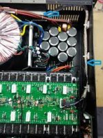
I recenlty bought a used t.amp Proline 3000 amplifier. The previous owner had unplugged all the wires between the transformer and the cap-pcb. I'm now looking for the information to help me reconnect the unplugged wires. I contacted Thomann but the could not share any documents. Also found this thread from this forum with a few diagrams but these did not contain enough information.
The information which I'm looking for is:
1) How to connect the wires coming FROM the transformer to the CAP-PCB.
2) How to connect the wires coming FROM the amplifier modules to the CAP-PCB.
I would be grateful If anyone here could take a few detailed images from under the hood of their Proline 3000.
CAP-PCB
The pins on the cap-pcb are (in the images I have defined the pin numbers myself):
Pin # / Label
01 / AC Input
02 / AC Input
03 / AC Input
04 / AC Input
05 / +VCC-H
06 / +VCC-H
07 / +VCC-L
08 / +VCC-L
09 / GND
10 / GND
11 / GND
12 / -VCC-L
13 / -VCC-L
14 / -VCC-H
15 / -VCC-H
16 / V~L
17 / V~L
18 / V~H
19 / V~H
20 / Multipin (2pins)
21 / Multipin (6pins)
22 / Multipin (5pins)
TRANSFORMER
from Transformer to CAP-PCB
Brown
Red
Red
Yellow
Yellow
Blue
Blue
Black
from AMP modules to CAP-PCB
Red
Red
Orange
Orange
Green
Green
Blue
Blue
Black
Black
Multipin (5pin) Green,Green,Brown,Brown,Black
If you get nothing in the next 7 days I will open up one of mine and send photos. (Too busy with work this week, sorry).
I have been searching for images. So far the resolution of the images has been the main problem, only small images. This is the best one I've found so far (still missing some details):

It is not easy maybe with some compination of photos found the right connections or other member like the above post open the case and send you pics.wish you good luck
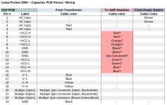
I have made some progress. Here are the results so far. Half of the pins have been easy to specify but for pins from 5 to 15 the results might be wrong. I have not found an image with a clear view of these pins. I had missed one GND pin between the caps, this is now numbered as pin 23 in the images below.
!! A close up photo of the area where pins 5 - 15 are would help to confirm the colors I have half guessed. Close ups of the other pins would also be appreciated.
The results of my research so far:


!! A close up photo of the area where pins 5 - 15 are would help to confirm the colors I have half guessed. Close ups of the other pins would also be appreciated.
The results of my research so far:
Attachments
WHY have the wires been unplugged.
Only reason to do this is if it is Faulty.
The previous owner used the amp as a part of his home hifi setup. He had started a project to replace components (none was yet replaced) to reduce the baseline noise. This project never got finished before I purchased the amp. I'm now just returning the amp to its original state.

I noticed today that the amplifier module has the wire connections labeled -> According to these my guess was correct.
The labels on the amplifier module:


I will connect the wires according to this and will confirm the result here afterwards.
The labels on the amplifier module:
I will connect the wires according to this and will confirm the result here afterwards.
Some infos in french :
https://www.homecinema-fr.com/forum/diy-kits-tweaks/the-t-amp-proline-3000-t30108994.html
https://www.homecinema-fr.com/forum/diy-kits-tweaks/the-t-amp-proline-3000-t30108994.html
- Home
- Amplifiers
- Solid State
- t.amp Proline 3000 - Looking for images to help rewiring