Anthropomorphous Center Channel

I attempted to make a center channel to follow the horizontal and vertical directivity pattern of a human speaker discussed in Analyzing the Directivity Patterns of Human Speakers by Christoph Porschmann and Johannes Arend.

If I understand the paper correctly, human vocals narrow horizontally as frequency increases but the vertical directivity is forward and down as shown in the image.

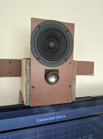
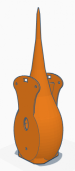
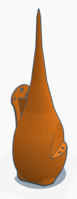
I tried to recreate the pattern by placing a head sized speaker above a TV screen which behaves like shoulders and a chest. The silver speaker (Aurasound NSW2-326-8AT 2" Full Range) is 5 feet 6 inches from the floor, same height as the mouth of a standing six foot tall person. The baffle is 6 inches wide by 11 inches tall, which is the same proportion as the head and neck above the shoulders. I placed it at that height assuming I'd get the same floor bounce as a 6 foot tall person standing in the room. The silver speaker is angled down toward the listener seats so it doesn't go above their heads as the higher frequency pattern narrows -- i.e. a six foot tall person angling their head down to talk to a person in a chair, which is what we do naturally. I also gave it a "chin" by placing the surface of the speaker 2 inches past the TV screen surface.

The baffle surface is flat, obviously different from the shape of a face. Researchers do use fully human shaped speakers when they research human speech directivity.

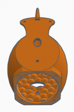
The low-mid portion (150Hz to 1k) is an open baffle 6" driver with an active assist from a 3" driver (Aurasound NS3-193-8A1). The 2" silver speaker is 1k to 20k that starts narrowing above 3k. At present, I run the 3" active cancellation from 150Hz to 3K. I cross between the 6" and the 2" at 1k. I think this reduces the ceiling bounce, which is probably ok.

I added a separate speaker below the screen to help pull the apparent source down into the TV screen and help the vertical polar pattern. I had to delay and attenuate it to make it sound right but I haven't decided if it's worth it. The goal isn't to get the apparent source into the screen, the goal is to approximate a human voice in the room.

Attachments

  • Screenshot 2021-02-05 133619.png
    Screenshot 2021-02-05 133619.png
    572.2 KB · Views: 105
  • PXL_20210205_211900122.jpg
    PXL_20210205_211900122.jpg
    332.8 KB · Views: 111
  • PXL_20210205_211908233.jpg
    PXL_20210205_211908233.jpg
    290.7 KB · Views: 105

Jaycar Reponse woofers

I have 4 only NIB CW-2137 for sale to help fund the repair of my Pre-amp.
They are supposed to be for a project but the repair takes precedence.
Specs from the 2004 cattle dog
Nominal 1-" woofer Sd 0.0346
6.9R
Fs 29Hz
Qms 7.632
Qes 0.347
Retailed $90- when buying the quad
Asking $300- plus postage
COD is fine Pick-up in in Geelong Victoria.
X-Max never stated but around 6mm, X-Damage closer to 10mm.
Really need to be used in pairs
Never used and never tested but I am using the Carbon Fibre versions and they do serious bass in a bigger ported box and usable in small sealed.
PM for more details Re pick-up
Post at cost plus packing materials

Choosing the right triode as a Phase Inverter

Greetings everyone,
How does one choose the proper triode for a phase inverter? Here are the specs on a triode (6M11) I am considering:

Triode Class A Amplifier
Plate Voltage 125 V
Grid No. 1 from 120 Ω
Amplification Factor 58
Plate Resistance (approx) 10K Ω
Transconductance 8K µ
Plate Current 8 mA
Grid No. 1 Voltage for Ib of 50 µa -4.5 V

Stetsom HL 800.4 protection transistor

Got a Stetsom HL800.4 amplifier that I repaired 1 channel on. The amp was in protection when I received it and during the process of the repair, the smd transistor was misplaced. I am unable to find out what it is by searching the markings on it. I think it says R8PXE(R0PXE?) on it and is a 3 leg component, same package as an MMBTA56 and the like. If using the configuration of the MMBTA56 in normal operation there is 5.6v on base(leg1) and emitter(leg2) and 0v on the collector(leg3). Any output voltage on leg3 would trigger the protection. Not sure whether a transistor, diode or switch can be used in this location but I would like to ask before inserting a wrong choice. In this amplifier, this component has leg1 connected to leg1 of IRS2092S and leg2 connected to leg5 of IRS2092S. It is Q24 in the attached pics.

Attachments

  • IMG_20210131_034559.jpg
    IMG_20210131_034559.jpg
    609.6 KB · Views: 301
  • IMG_20210204_215302.jpg
    IMG_20210204_215302.jpg
    987 KB · Views: 234

Anyone heard the Yamaha YDA 138-e chip?

Apparently it's Yamaha's answer to the tripath 2024 class d chip.
Yamaha YDA138 E Class D Power Amplifier Board | eBay

IMO, the 2024 is the best sounding tripath chip, tho it,s low power and has a few minor sonic drawbacks. I.m curious to know how Yamaha stacks up here.
Back in the 80,s and 90,s Yamaha made good performing audio, and it was the only Japanese speakers that I thought sounded pretty good.

Cabinet design primer for vintage Zenith speakers

Hello there,
I bought a pair of 12" Zenith 49CZ1027 so I can compare them with the 10" Audio Nirvana Classic AlNiCo I already have.

I have an AN 300B SET and might build a 45 or 2a3 DIY later, so I'd like to build a pair of bass reflex cabinets to squeeze some extra Db's out of the drivers with a simple design. Although I have built cabinets for my AN 10" before, as soon as I looked at a cabinet design calculator I realized that I miss some key information.

My questions:

1. Does anybody know where I can find technical specs for the above mentioned drivers so I can punch in the right numbers?

2. Is there a generic cabinet design for full range 12" speakers, and is it advisable to go that route if I can't find more info on my speakers?

Thanks.
gm

Another TC9 Line Array Project

Good evening all

Following a recent house move I have been provided with a new opportunity to design some speakers to fit in a new space in the new house. Thanks to the new world we live in, one room upstairs has gained the honorable triple designation of guest room/Phil's office/music room.

Following a few ideas, including one that was discussed on this forum, I was pointed towards considering a line array solution. After a ton of reading, a bit of planning, some design work and a few mistakes along the way, I have a fairly robust concept (I think) which is now firmly into the production phase. Given the amount of support I have received from this community, both actively through feedback to previous posts and passively through reading other people's experiences, I thought it would be good to share my project and perhaps get some feedback.

The basis for the concept was driven by a couple of defining factors. The room will have a king size Murphy bed along one wall which would also be the prime location for audio equipment and speakers. Given the width of the Murphy bed, this does create a bit of a challenge in trying to not push the speakers too far apart. Secondly the speakers need to be very efficient as I have a pair of mono-block tube amps that output about 6W max. After contemplating a variety of single FR driver solutions, someone suggested investigating a line array solution. After a bit of research and comparison of 2-way design vs FR design, I decided to go with a FR line array concept given that I will be far enough away from the speakers to not have to worry about comb effect, and based on a few folks here who have had great success with FR line array concepts. After a bit of online research I also came to the conclusion that the best driver to start with as the basis of the design would be the TC9 from Tymphany, again based on others' success and the relatively low cost of the drivers.

Given my wood working skills are pretty weak and I have recently gotten into 3D printing I decided to see if I could come up with a modular design for a line array. The basic idea was to create a 3D printed box for each driver that would be easily stack-able in any quantity desired to give a full line of drivers. For those that are not familiar with 3D printing techniques, flat surfaces and right angles can be challenging to print efficiently (read with using a ton of material) and the most robust (read strong) designs are often curved in nature. After looking around for some inspiration I was drawn to the B&W Nautilus design and set about seeing if I could create some sort of facsimile.

My initial concept was what I would describe as a tadpole. A driver mounted to a spherical box, linked to a elongated conical tail, stretched out as long as my print capacity would allow. In order to make this design stack able, I then applied a flat edge to the top and bottom of the spherical area at the same width as the driver which would also allow the drivers from adjacent units to be as close together as possible to reduce comb effect as much as possible.

The next step was to create a wing to provide more depth to the interface plane between 2 adjacent boxes to provide more structural stability as the line is put together. Into the wings I added 2 6mm holes to allow adjacent units to be bolted together and an interface point for the stand clips (more on that below).

Inside the box I created a single 6mm hole near the front of the flat side to provide a forward bolting point for adjacent units. I also created 2 oval shaped holes in perpendicular planes with one located towards the front of the box and one towards the back. The purpose of these holes is to provide some leakage between adjacent units, but also to allow wiring runs between units. By offsetting the holes from each other I hope to avoid creating a single large vertical chamber through all the vertically stacked drivers.

The final internal design element was to place a pattern of irregularly spaced shallow cones in the inside of each of the flat surfaces on the top and bottom of the unit. The cones are intended to ensure there are minimal parallel surfaces internally, thus reducing the risk of standing waves inside the box. The pattern of cones also has the nice side effect of making the flat side of the box thicker and thus stronger and more resistant to vibration. The rounded elements both in the spherical box and the tail are proving phenomenally strong at even just a few millimetres of thickness when printed with standard PLA type materials.

On the front face of the box I put holes to allow knurled threaded inserts to be placed and then heated so they would melt slightly into the plastic and provide an anchor point for the driver screws.

The finalized box design has an internal volume of approximately 1 liter (measured by filling one up with water) and each box will be liberally stuffed with polyfill.

I am creating a driver flange seal from 1/16" neoprene to be mounted between the driver and the box, to try to help reduce vibration transmission from the driver cage to the box and vice versa. I intend to place a thin layer of clear silicone between the units as I begin to stack them up to both help with stability and again attempt to reduce any potential vibration propagation between units as far as possible. I did consider some more exotic acoustic treatment for between the boxes like Decidamp DC30, but found it hard to come by, and not sure I need that much damping between the boxes.

The final design element is a mount to allow me to attach the arrays to the sides of the Murphy bed. The relatively simple design interfaces with the back of the winged section via 2 raised triangular raised surfaces that click in to the holes created on the wings. This provides a sturdy interface yet there is enough flexibility in the wings to remove the box from the stand if required. I have yet to test this design with the weight of multiple boxes, but for my 25 driver array I intend to have 6 mounts.

My wiring plans at this moment are simply 5 groups of 5 drivers in series. I do not intend to do any power shaping as I have seen good feedback from others that have not done this.

I have also taken all the relevant design principles and created a single box solution to allow me to put 1 driver in a box of broadly the same design to check the performance. Now I will say I have not done any formal measurements, but the single box with 1x $9 driver in it, playing summed mono output actually sounded really good. Obviously lacking in bottom end but I do plan to build some sub woofers to support the lower end once the arrays are complete.

So that's my journey so far. Each speaker box takes roughly 28 hours to print and so far I have only produced 4 of the 50 I will need, so it will be some time before I get the project complete. My next real world test plan is to get an array of 7 drivers put together and see how they sound.

If anyone has any questions, comments, suggestions, or ideas please let me know. I will attach some pictures of my design files and progress to date, and will look to keep updating this thread as I make further progress.

Phil

Attachments

  • Line Array Module 1.PNG
    Line Array Module 1.PNG
    20.5 KB · Views: 632
  • Line Array Module 2.PNG
    Line Array Module 2.PNG
    24.4 KB · Views: 621
  • Line Array Module 3.PNG
    Line Array Module 3.PNG
    96.9 KB · Views: 609
  • Line Array Module Bottom.PNG
    Line Array Module Bottom.PNG
    21.9 KB · Views: 604
  • Line Array Module Top.PNG
    Line Array Module Top.PNG
    21.1 KB · Views: 625
  • Line Array Module Stand.PNG
    Line Array Module Stand.PNG
    14.9 KB · Views: 175
  • IMG_20201016_205607.jpg
    IMG_20201016_205607.jpg
    350.5 KB · Views: 234
  • IMG_20201016_224006.jpg
    IMG_20201016_224006.jpg
    384.9 KB · Views: 258
  • IMG_20201016_224125.jpg
    IMG_20201016_224125.jpg
    358.9 KB · Views: 262
  • IMG_20201016_205616.jpg
    IMG_20201016_205616.jpg
    395.4 KB · Views: 279
  • Like
Reactions: thalesdecastro

Need help with IB woofer choice

Currently I have 2x 210mm holes in my floor under my front seats in my car, made originally for satori wo24p-4 woofers, that have since been changed to a single ten inch subwoofer with a inverted surround so the surround doesn’t hit the metalwork, now the subwoofer is getting low enough (the satoris weren’t ideal for this, perhaps a bit limited on xmax for the displacement needed at low freqs)

However the satoris were a very lice low midbass driver, they were more articulate at low freqs vs the current 10” hybrid audio clarus subwoofer I have under the passenger seat, what I need is something somewhere between the two drivers, more xmax than a satori with a higher Q ideally, and a bit more finesse than the clarus 10” subwoofer

Also when removing the clarus I have noticed condensation on the cone (they are inverted), so I am now at a point when I’m considering refitting the satori as midbass is more important than sub bass for competition

I am only playing the clarus upto a 150ish he crossover but it’s sound is a little thick, now it’s cone is made of polypropylene and so not bothered by the moisture whatsoever

I am curious if anyone had some suggestions for a nice compromise between the two drivers

Metal/plastic/man made cones are all welcome (just not paper), QTS between 0.5-0.9 considered, low fs ideally in the 30’s or below, and 8-10”, but must have decent xmax for the lowest freqs, thinking maybe if someone has done open baffle subwoofers or similar, depth can be anywhere upto 150mm and no larger diameter than 290mm ideally

Suggestions welcome

Or alternatively a method of waterproofing the satori as they were almost perfect bar the very lowest notes, but I can always make a second preset with some boot sub woofers and use the satori purely for midbass dutys for ‘excitable’ listening levels

Building Cornscala Bob Crites

Dear readers,

I'm looking for a friend of mine in Northern Ireland for someone reliable to build him two cabinets for his Cornscala Typ B.

He has all the parts from Crites, but the guy who promised to build him the cabinets has backed out of the deal.

This is no freebie, it will be payed, but will rely on perfect build.

Please respond, he is realy down with him being stuck with all parts for a great speaker and never be able to listen to them.

With kind regards,

Kermy 666

  • Locked
mje243/mje253 spice models - completely different results

I tried to run wingspread simulations to compare the gain curve of two different spice models. While I expected to see differences in the gain distribution the almost opposite direction of the slope and the depth of the waviness of the curve surprised me a bit.
On-semi spice models
mje243_253_on_semi_bjt.jpg
Cordell spice models
mje243_253_cordell_bjt.jpg
I believe that Bob Cordell's models can be trusted, although the smaller and more rippled gain on the npn side is somewhat counterintuitive. On the other hand, I have read about the problems the factory on_semi models cause with ac analysis and the difference in the dc transfer of the two transistors is glaring here. And this is where doubts arise about the accuracy of other available models. I've just started exploring the simulation world from so-called 'kitchen side' and I can't quite verify how the code matches up to reality. Can the stock LTspice library be trusted and which manufacturer's resources should be avoided?

Cheap and capable chineese amp board?

My brother-in-law needs a new amp for his vineyard-house. The thing is, it will never be used for hifi. He needs it for driving some old and pretty big speakers, sometimes playing out the window for vineyard workers or as we call them here in Slovenia, party animals. Onboard potentiometer is a must, onboard RCA is nice, loudness is mandatory.

Excellent Quality TDA7498 100W+100W Class D Amplifier Board High Power Amplifier Board Hot Sale Easy To Install-in Amplifier from Consumer Electronics on Aliexpress.com | Alibaba Group

TDA7498 Class D 2X100W Dual Channel Audio Stereo 80W + 80W Digital Amplifier Board Module Free Shipping-in Amplifier from Consumer Electronics on Aliexpress.com | Alibaba Group

How do you find these two? Or should I look somewhere else?

Mission Cyrus 2 rectifier diodes replacement

Hi All,


I have a Mission Cyrus 2 amp and while servicing it (recap) I've found that the rectifier diodes (probably) have been replaced in the past as there are 2 GI852 (fast recovery 3A diode) and 2 8827 diodes (can't find any info about it).
according to the service manual there should be 4 PFR852 (3A rectifier diode which have the same specs as the GI852).


I've found an ultrafast soft recovery diode, the Vishay UF5402 to replace the rectifier diodes in my Cyrus 2 amplifier.
looking at the datasheet of the UF5402 it seems that there is one difference between the 2, I would like to know please how important is the marked parameter in the attached datasheets?
Can the UF5402 diode safely replace the 2 GI582 and the 2 unknown 8827 diodes in my amplifier?


Thanks

Attachments

  • UF5402.jpg
    UF5402.jpg
    131.4 KB · Views: 244
  • GI852.jpg
    GI852.jpg
    109.4 KB · Views: 230

Glassware ACF-2 Aikido hum problem

Hello there,

As the title says, I've got a wee hum problem with an ACF-2 tube buffer I've just built, using 6SN7 tubes. Bloody things sounds really nice but the hum is killing me (what has been heard cannot be unheard).

First, I thought this was a ground loop (or an earthing issue). However, I looked at it from all angles and I don't see any loops. The chassis is tied to mains earth right at the input. The board is connected to the chassis from the house ground pad, through a little board I made myself, that has a power 10-ohm resistor and a small cap in parallel, together with 4 diodes in parallel as well (pairs of two). I've tried disconnecting the board from the chassis (leaving the chassis tied to earth), without any success.

The input/output jacks are isolated from the chassis (verified this with my multimeter) and signal grounds are paralleled all the way to the board. I have shielded part of the signal wires, but the shield is connected to signal ground only at one end.

From this, I started to suspect this is heater hum. I've measured it to be "exactly" 50Hz and I also noticed the hum goes away almost instantly after I cut power to the unit (however, some 30s after that, the power amps start to hum terribly loud - not particularly a problem as I never use them like that).

My mains transformer is a Hammond 369AX, which has a 6.3VAC secondary. It's currently wired in the Full-Wave Bridge configuration and I'm thinking the regulator doesn't have enough input voltage to output properly filtered DC, hence the noise. I am considering reworking this into the Voltage Doubler config, while keeping the reg output at 6.3V. It should dissipate a lot more voltage, but I would assume the DC should but much cleaner.

In any case, I would appreciate your input and opinions. Also, if required, I can provide some pics tomorrow

Schematic help

I purchased this LM3886 amp from ebay several years ago and looking for a schematic. The amp is no longer for sale, and the company listed on the box (nyplatform.com) does not respond to questions...they may no longer sell it.
Board made in China. MK154.

I've attached a picture of it. I want to change the voltage divider to use it as a 40 watt amp, but can't seem to figure it out. It would seem that the resistor indicated is the resistor between pin 3 and 9, but with my meter I don't get the connection to pin 9 on the other side of the resistor. Looking for the resistor to ground, I guess it is the 6.8K next to it, but again no reading to ground?

Anyone ever use one of these amps?

Attachments

  • MK154 Modifed.jpg
    MK154 Modifed.jpg
    388.1 KB · Views: 158

Non-complementary class AB linearized amp

Hi,
I designed, built, tested and listened to this amplifier. Its circuitry is a bit different, but I find it sounds very good (very difficult to tell it apart from a tweaked Linn amp using blind, level-matched AB switching), and it does not generate the excessive heat from a class A design.

Its design is based on a non-complementary BJT circuit. It runs
class AB, and uses current amplifying stages instead of voltage
amplifying stages (VAS) to drive the output transistors. The output
stransistors are in a totem-pole configuration, but run common
emitter rather than the usual common collector (emitter follower)
layout. The front end of the amplifier uses a differential compound
pair (Sziklai).

The first transistor after the differential pair is biased such
that instead of cutting off sharply for class AB, it has an
extended non-linear cutoff to minimize the impact of "crossover"
distortion. This base circuit also compensates
for the inherent non-linearity of the "gm doubling" of the output
transistors when run class AB. The result is that over the entire
operating range, the openloop gain of the amp doesn't vary more than
5-10%. Closing the feedback loop with about 60db of loopgain results
low distortion.

measurements using +21/-21 volt power rails:

Output power (.003% distortion) 35 watts @ 4 ohms
output power (.1% distortion) 45watts @ 4 ohms
freq. response: 10Hz-50KHz +0-3db
Low freq. limit set by coupling capacitor, can be eliminated for DC
Slew rate: 5V/us (can be increased but requires 10uh in parallel with 10
ohms in series to load)
Capacitive loads: stable (with 2V/us slew rate) with 1uf low-ESR load.
Distortion (@ 1khz): 2nd harmonic below -90db for 35 watts or less
3rd harmonic below -85db for 35 watts or less
higher harmonics below -90db for 35 watts or less
Output stage protection: output voltage diode clamped to rails
output current limited to 4 amps after 10ms
DC on output: adjustable to zero, stable to a few millivolts.

I enclosed the schematics and an LTSpice ".asc" file to show the gain linearity while the input is DC swept. Plot the derivative of the output voltage "d(V(Vout))". The circuit requires the Cordell models for MJL3281, 2N5089, 2N4403. I have used MPSA56 transistors extensively, and the SPICE model is on the ON Semiconductor site, or just use 2N4403's instead. MPSA56's were popular 'cause I had a whole pile in my transistor bin.

The circuit is a bit of a fluke.... it originally was a class A design - one of the design iterations showed better performance running class AB! You can probably greatly increase the power output with higher voltage rails. I didn't need much power, and I had a pair of transformers scavenged from a few cheapy UPS's that would only do 21 volts DC.

Feel free to use the circuit as you wish, please tell me if there's anything you think that might improve its sound.

Paul G.

Attachments

Nixie question

I am going to put a pair of 2 digit displays on my amp chassis for the volume readout for each channel. I noticed there is driver chips that decode binary and drive the tubes. Why is this necessary or is it? I was planning on making a circuit board that goes behind the volume knob with two pads patterned in an array that coincides with the steps in my volume switch and put a beryllium copper contact tab on the back of the volume knob that bridges the 2 rows of pads and use that to send the b+ to the nixie tubes. Any reason what I plan isn't a good idea other than having the voltage right there where you touch the amp. I can make it so that is safe. I could drive relays off a 5 volt signal as well. But is there any reason I would want the driver chip?

15 W out of single SE KT88 ?

Guys,
I see number of SE KT88 amplifiers on the market advertising 15W outputs power.
Any ideas how do they do it ? How do they get 15 watts out of single KT88/6550 tube ? I think, they use tube in pentode mode.
I have breadboarded a simple KT88 amp using 2.5k OT and I only get about 6...8 watts before onset of clipping. Supply voltage is 400vdc and I used fixed bias.
Any comments ?

Thanks
Sergey

F5 Boards Jims Audio

Hallo Guys
For Sale
Due to lack of time, I offer F5 boards from Jims audio and with the appropriate resistors from the original F5 bom list, which is noted as OK.
Everything has been bought from digi key and if you don't trust it, I can also send the invoice. I would like 50 € plus shipping.

Greetings Alfred

Attachments

  • Bild (56).jpg
    Bild (56).jpg
    519.8 KB · Views: 240
  • DSC08890.jpg
    DSC08890.jpg
    755.1 KB · Views: 230
  • DSC08889.jpg
    DSC08889.jpg
    908.7 KB · Views: 221
  • DSC08887.jpg
    DSC08887.jpg
    755.7 KB · Views: 211
  • DSC08888.jpg
    DSC08888.jpg
    829.9 KB · Views: 218

Allen & Heath Xone 92 Pro DJ Mixer Value

I was at a high end equipment music store up in Wisconsin and also saw one of these XONE-92 mixers. This one is silver faced. It's been used only about a few times. It's been kept in it's original carton, and doesn't have a nick or scratch on it. Most I've seen are black. It too sophisticated and professional for the owner who had it. What would this beauty go for today as far as value wise?

300B tubes

I just love the sound of the Genalex 300Bs. I haven't compared many in my amp only the PS Vane "mesh" perforated plate tubes and there is a pretty big difference between the two. The genalex sound better across the whole range IMO. Much more bass and better bass. The sound is fuller. Not as brittle as the PS vanes. I had a heater fail on one of my genalex tubes and so I was without them for several months. Today a new tube arrived for my Genalex pair and I haven't stopped listening since it got here... even with uneven age of tubes it still sounds fantastic. I wasn't going to not use a $150 tube just because its a little older than the other one.

WHAMMY vs Noir

I'm trying to decide between the Noir and the WHAMMY. Anyone built both and have comments about how the build went and how they sound?

This may sound silly, but my biggest hesitation with the WHAMMY is the rectangular IEC socket. The last time I built an amp with a rectangular IEC socket, it sat on plywood in prototype phase for about 5 years until I got an internship at a place where I had access to a machine shop with a real milling machine where I could finally get the casework right, particularly that pesky rectangular hole for the IEC socket. I don't work there anymore and therefore no longer have access to a milling machine, just my basic benchtop drill press.

So the Noir appeals to me in that way since the casework is taken care of.

But what about how they sound, how they work with a variety of headphones, or how the build went besides the casework?

Thanks,
Kevin

Humble Homemade Twenty Five KIT

Hello there :wave2:
I'd like to sell my Humble Homemade Twenty Five kit designed by Tony Gee since I just built TG's Nomex 164 MKII.

It was my first DIY venture, I bought it in July 2019 for 300€.
Here is a link to the project page: http://www.humblehomemadehifi.com/download/Humble Homemade Hifi_Twenty Five.pdf
The crossovers are the standard version.

I'd like to sell it for 180€ including shipping to Europe through Mondial Relay only (France, Spain, Portugal, Italy, Luxembourg, Germany, Belgium, Austria and Netherlands).
I'd rather receive payment through PayPal (the fee is not included if you choose to be insured so you'll need to add 3% I think) or through a bank wire.
I'd rather sell it to someone located in continental Europe.

Everything on the table is included, I will provide enough egg crate foam to build the whole kit and I added some Dacron to dampen bass if needed.
4 black wood screws were missing so I added 4 steel ones but you might want to replace them.
The paint on one of the tweeter is chipped but you can find them for less than 10€ if you want to replace it.
If you have any question, don't hesitate and send me a message!

Best,
MnK
IMGP6234.jpg

IMGP6235.jpg

How Much Distortion Can You Tolerate?

Compare original and distorted audio from any .WAV file.

The latest version of the program matches RMS power for comparison pairs. This makes it easier to discern small differences in sound quality. You can now try fourth-harmonic distortion as well as second or third. Fourth is particularly nasty. Finally, you can specify distortion in either percent or dB.

How Much Distortion Can You Tolerate?

Brian

Guidance Appreciated: Amplifier with very low volume output on all channels?

Hi all,
I have started my journey repairing amps during this pandemic and it has been thoroughly rewarding.
Thanks to reading through this fantastic forum I was able to repair a handful of friends and relatives amps. 👍👌🏼👌🏼

My knowledge is very basic but I am willing to learn.

I have now come across an issue with an amp that powers up fine (Orion HP-4800), no protect light, but the volume output is very low on all channels. I cranked the gain to the max and no change in output AC voltage at the speaker terminals, the RCA input voltage I used was about 250mv with a 40hz sine wave. I removed the gain pot and tested the resistance and it was fine. I checked all the output Fets for shorts and they where also all fine. I am thinking there is something wrong on the preamp section that I need to check or replace, but I don't know where to start.

Anyone's help would be greatly appreciated.

Regards Jay

2 layer voice coil Seas L26roy vs 4 layer

I'd like to include the Seas L26roy in my subwoofer shootout I've been doing on this forum. A tale of 12" subwoofers, distortion and 15 dollars.

Would the Seas L26ROY - X1001-04 with a 2 layer voice coil be better or the Seas L26RO4Y - (XM004-04S) with a 4 layer voice coil?

My testing includes testing for the max spl while under 5% distortion as well as some subjective comments from music listening.

My intuition is the 2 layer voice coil will have less inductance modulation and therefore lower distortion but the late great S. Linkwitz used the 4 layer version.

I think Hobby hifi magazine tested both but I'm not sure.

Also let me know if you have one for sale.

Overload Protection Engages as Volume is Raised

Got an amp for repair with completely blown up output stage. Replaced all output MOSFETs. Amp powers on, DC offset is around 1.5mV. Music plays from the speakers, but as soon as I raise the volume (and this is not loud at all, speakers just hardly audible), the amp goes into standby and displays an overload error message. Looking at the amp’s manual, this message comes up if there’s a short in the output. Looked everything over and can’t seem to find any problems. Just looking for any suggestions, or something that I might have overlook. Thanks guys.

2-way with Wavecor SW182BD

Hi there,

I have some bits and pieces from previous unfinished projects and I was thinking using some of using them in a new project 🙂 However, before I begin I would like your opinion.

My idea is to make a pair of active 2-way speakers of approx. 10 liters with a passive radiator.

Here is what I have:

Here is what I’m thinking of buying:

  • 2 x Wavecor PR182BD01 (PR182BD01)
  • 1 x 4-channel power amp or 2 x stereo power amps
The Wavecor SW182BD02 models well in a 10 litre enclosure with a passive radiator PR182BD01 tuned fairly low to 20-25Hz. The speaker's dimensions would be something like 35x20x25cm / 13.8x7.9x9.8in (HxWxD). The passive radiator placed on the rear.

The SW182BD+PR combo was tested in Voice Coil magazine with good results. From the test I quote:
“While the SW182 is billed as a subwoofer, a crossover frequency as high as 2kHz is certainly possible.” (http://www.wavecor.com/SW182BD01_in_Voice_Coil_Feb._2010.pdf)

The SB26 tweeter was tested by Jeff B (he tested the SB26STAC with alu faceplate, but I assume it performs similarly to the non-alu version I have). From the post I quote:
“Overall I think the SB26 is a very nice tweeter with good performance for the money […] When looking for a smaller, true 1" dome tweeter with very linear response, an attractive appearance, and an expected crossover point of 2kHz or higher I think it should be on your list for consideration.” (SB Acoustics SB26STAC Tweeter Tests)

I assume that both Voice Coil magazine and Jeff B are talking about passive crossovers here. This got me thinking that e.g. an active LR4 (or maybe LR8) @ 2kHz could work.

What are your thoughts on this project?

Thanks,
Søren

Exciting day

I am awaiting the postman to bring me my new TVCs for my 300B/D3a SET amp. Autoformers from Dave Slagle. Also a new pair of caps for my power supply and this book. See attached.
I fixed my amp this last week after 6 weeks of pulling my hair out trying to figure out what was wrong with it. Turns out it was a bad PCB. I drew up new ones and had them made and it worked first time I wired it up. And was dead silent.
Also put a new pair of Duelend Cast copper PIO coupling caps in it last week also. So the volume control is about the last thing left to finish it off.
Can't wait..

Attachments

  • image_2021-01-23_100852.png
    image_2021-01-23_100852.png
    307 KB · Views: 696

Power transformers

For sale some used power transformers. Those from the projects that were never happens

1) R-Core 150W 2*26V (CT) 2.4A 1*27V 0.5A (under load)
$25 + PP fee and actual shipping cost

2) EI transformer 2*104V 0.2A (under load)/ 1*145V .15A/ 31V (CT) 0.5A/ 2* 6.3V 2.5A with cast aluminum covers.
$25 + PP fee and actual shipping cost


All shipping from Pittsburgh, PA (15222)

Thanks

Attachments

  • IMG_20201223_155055499_HDR.jpg
    IMG_20201223_155055499_HDR.jpg
    225 KB · Views: 323
  • IMG_20201225_174403173_HDR.jpg
    IMG_20201225_174403173_HDR.jpg
    127.8 KB · Views: 322
  • IMG_20201225_174438478_HDR.jpg
    IMG_20201225_174438478_HDR.jpg
    180.3 KB · Views: 316
  • IMG_20201225_174328188_HDR.jpg
    IMG_20201225_174328188_HDR.jpg
    79.2 KB · Views: 319

SUT Question

I wondering if one can run two SUTs in series to achieve higher gain? I have a very nice sounding phono-stage using D3A > 5687 but even with a 1:20 Sowter SUT I am just getting marginally enough volume. I built it with octal mounted transformers and 1:20 is as high as they carry. I bought the 1990s which can be switched between 1:10 and 1:20. Si I'm thinking I could add another stand alone SUT and feed that output into my phono stage.
Thoughts?

Toroidal power transformer ADCOM

For sale toroidal power transformer from ADCOM 5 ch power amplifier (model 6000).
2 set of secondary output 2x40V and 2x38V (idle). It will be around 2*50V + 2*60V after rectifier.
Transformers is about 450-500W.

How about $35 + shipping from ZIP 15222?
welcome for local pickup from Pittsburgh, PA.

Thanks for looking.

Attachments

  • Adcom pwr (3).jpg
    Adcom pwr (3).jpg
    328.4 KB · Views: 257
  • Adcom pwr (2).jpg
    Adcom pwr (2).jpg
    265.4 KB · Views: 252
  • Adcom pwr (1).jpg
    Adcom pwr (1).jpg
    374.6 KB · Views: 244

Pyramid pa800x

Hello Friends 🙂

I have this Pyramid pa800x Left Channel works fine But Right Is the Problem.
I had replace all Final Transistors with 2sc5200 and 2sc1943 Because my pa310 model has that inside. I decided to put in two Transistor one each into corresponding slots. Powering up the amp with only two Transistors the Transistors get hot and blow the fuse. At first I though I bridge a Positive rail with Negative. I recheck every soldering and everything was fine. I replace the fuse and power up back again. Fuse burn and transistors were extremely hot (only 40seconds it was on for) I had remove the transistor and test them they were burn. I test the volt for the collector in the PNP section it was -57v For the NPN section it was 57v. I check the volt on the Emitter it was -47v on both PNP and NPN Section...

Is that volt suppose to be there at the emitter pads?

I had check the Driver Transistor THey Are good but the Base and Emitter Pad were fluctuating between -47 to 47v Sometime it is stable 32v

Any ideas what may be the problem?

Thank You in advance 🙂

ROTEL RA-913 parts substitution

Hello.I need to replace all of the transistors in Rotel RA-913.This is what i came up with:

MAIN AMP
2SC1403A--->MJ21194G
2SA794--->KSA1220AY
2SC1567--->KSC2690AY
2SA921S--->KSA992F
2SD571L--->BC639-16
2SC1885--->KSC3503D (cant find E or F suffix on mouser)
2SA912--->KSA1381E

TONE CONTROL
2SC1327--->KSC1845F

PHONO
2SC1980--->KSC1845F
2SA750--->KSA992FB

Any suggestions?

Crossover design - No tools first step

Hi, guys.

First off All, I'm triyng to do the things at the lowest budget possible. Buying a lot of tools isn't an option for now.

I hope you all understand that is not my option, it's my reality.

Well... A Have a pair of old Sony 2 way Speakers (8" woofer/ 2" Tweeter) in an Onkyo TX-SR500.

For my first Crossover design I just want to get the single caps out and made a Crossover to put in place.

What's the most important thing to consider in this case?

Tank you all.

Crossover for Linkwitz LX521

My friend and I are both interested in setup a Linkwitz LX521 speaker system in DSP config.
LX521 Description
http://www.linkwitzlab.com/LX521/LX521-DSP-system-c.jpg

Other than miniDSP 4x10HD, can I use Lake LM-44 for the DSP setup of Linkwitz LX521??
LM 44 | LM SERIES | Lake | Categories | Music Tribe - Lake)
Or do you have a better option for this application?

Thanks!

is this a reputable UK-based dealer?

Is this by someone blissfully unapt, a fake store or a practical joke?

Audio Equipment – Buy - stones-and-roses.co.uk

First of all, no https, not even in checkout

Great deals on some audio electronics and drivers. Strangely, store categories and item descriptions are a major mess. Strangely, most articles are either GBP 33, 34 or 35, no matter if a cable worth 2 or a driver worth 100. They also offer free shipping to a host of locations, and normally free of duty.

Strangest is this part from their terms and conditions (mind you, they pretend to be in the UK):

INTERNATIONAL USE

Our Shop makes no representation or warranty that this Site and its Material are appropriate or available for use in locations outside the United States. Accessing this Site or the Material from territories in which this Site or the Material is illegal is prohibited. You agree that if You choose to access this Site or Material from any locations outside the United States, You do so on Your own initiative and are solely responsible for compliance with local laws.

MISCELLANEOUS

If there is a dispute about these Terms or Your use of this Site, the laws of the State of California, United States of America, shall apply, without regard to any conflict of law provisions, and it shall be resolved exclusively by the state and federal courts sitting in California in the State of California, United States of America.

FS: headphone tube amp project (for parts) UK

Having a clear out and found this teenage project. Its a valve headphone amp based around EL84 but I don't suggest turning it on is safe at all! (and no valves are included). However I thought it might be of interest here as there are some decent parts that could be re-used:
1* 1:1 isolation transformer
1* 15-0-15 shielded toridal transformer
Valve bases
Nutrix RCA and headphone sockets
19" 2u rack mount chassis (some holes obviously already drilled but would patch up)

It looks like some of the capacitors have started bulging in all the years its been stored and the wiring is super suspect been done very cheaply by my young self so please don't apply power to it.

I'm looking for £20 basically to cover postage (UK only sorry wouldn't seem worth sending it elsewhere) or it can be collected from Warrington WA4.

Attachments

  • back.jpg
    back.jpg
    62.8 KB · Views: 272
  • bottom.jpg
    bottom.jpg
    53.3 KB · Views: 257
  • front.jpg
    front.jpg
    75.4 KB · Views: 263
  • internal1.jpg
    internal1.jpg
    212.2 KB · Views: 266
  • transformer.jpg
    transformer.jpg
    506.5 KB · Views: 258
  • transformer2.jpg
    transformer2.jpg
    499.7 KB · Views: 168

Suggestions DIY line stage with bass and treble pots

Hi, I'm fairly new to diy but would like to build a solid state preamp that can compete with $1000,$1500 to $2000. I would really like to have bass and treble knobs, all my other preamps do not have bass/treble so this is new to me. In its use it will be used more for casual listening. Connected to ICE amps, so not sure if I may need a buffer between pre and amp to match input/output impedance or will the diy pre be able to match the amp. I'm having hard time finding out input impedance of ice amps but I did hear maybe 45 ohms if memory serves me correct. Thanks for any suggestions for a nice full bodied detailed pre, it would be very appreciated.

MR13P vs MR16P distortion

After a lot of research and head scratching, I finally decided on the Satori MR13P for my home theatre 3-way LCR speakers. I'm currently really bothered by the high distortion levels of my of my 2380 horn, so want to be absolutely sure that my new speakers will not have this problem. I find distortion in the vocal range very audible.

I came over some distortion measurements of the MR13P, and comparing it to MR16P measurements from the same source, it looks like the MR13P has some excessive distortion at around 1.4Khz. 2% at only 92db/1m.

Is the MR16P a better driver for 350-2500Hz operation as indicated by the measurements? I would prefer the dispersion from the smaller driver, but low distortion is a higher priority.

SB Acoustics Satori MR13P-4. A New Home Audio 5.25” Midrange Driver | audioXpress

The MR16P-4 6.5” Satori Midrange from SB Acoustics | audioXpress

Mark Levinson ML-9 transformer noise

Hello

Just bought an ML-9 in very good shape, all original, no hum through the speakers. But it has a very loud transformer noise. It is a combination of hum and rrrrrrrumble 🙂. Sometimes it nearly disappears, but then it comes back. I looked inside, and the trans is a huge toroidal job enclosed in a black round case. Being held by 5 bolts to the bottom, all tight. Any info on possible fixes?

Thanks in advance

Mark

Using IGBT modules for low freqency Class D ?

Hi.


I think about a subwoofer Class D design for large car hifi woofer in halfbridge design without an army of countless single mosfets.


There are industry igbt bricks, but they are slow compared to Mosfets.
I think the lower switching frequency cause larger filter output coils.


max output frequency should be around 200HZ.


I think about following IGBT module (Double IGBT H Bridge) IXYS 400-12E4


Datasheet here http://datasheet.octopart.com/MII400-12E4-IXYS-datasheet-8358599.pdf


tdON: 170ns
tr:60ns
Tdoff: 680ns
Tf: 50ns


Could this IGBT be useful for a design like this ?
I read about 10 times higher switching frequency then Output frequency.
Using 100 times more would be 20khz.


Regards

Power Dissipation vs Die Temp Calculator

I came upon this nice calculator which seems very helpful if someone understands how to use it:

Power Dissipation vs Die Temp | Design Center | Analog Devices

unfortunately I don't clearly understand all of the parameters that need to be entered:
VOUT Load voltage? does it mean Vrms??
VGND Load ground? isn't that always "0" ??
RL Load resistance? talking about an amp's output BJTs or FETs do I have to enter speaker's load??

FS: DIY Synergy horn speakers "CoSyne"

These are horns I built several years back. 3-way, 9 driver, co-entrant/coaxial/point source, controlled directivity, linear phase speakers (my own design). There was a build thread at DIYSoundGroup, but apparently it didn't survive the move when they changed their website.
front.jpg
Here are some related threads, though --
DIY Synergy/Unity spreadsheet | HiFiCircuit
http://www.diyaudio.com/forums/multi-way/219870-have-diy-synergy-speakers-doing-almost-linear-phase.html

They are 24"wide, about 48" tall, 12" deep. big but not enormous. But they would be "pick-up only", I don't want to try to pack them for shipping nor deal with crises if they got dropped! Location is in Portland, OR.

Carpentry and finish are "diy" oak veneer (horn is rough-painted mdf), not pro-furniture-craftsman, but I think they would be decent looking in most home decors.

Asking $500 for the pair, a little below the total materials costs, to include several spare drivers of each type.
back.jpg

InsideCaab.jpg

Attachments

  • boxes.jpg
    boxes.jpg
    23.5 KB · Views: 1,251

Building a Chinese clone of ARC LS 10ish

Hi guys, I am an audio enthusiast, retired and therefore on a tightish budget. I like to keep my mind active and building kits etc is the way I do it.
I have already purchased this kit : Hi End AudioResearch ARC Tube Preamplifier XLR Balanced Or RCA Input&Output,12AU7/ECC83+ECC88/6DJ8 Preamp DIY Kit-in Amplifier from Consumer Electronics on AliExpress and was just wondering if anyone else has built one and what the sound quality was like.
I have purchased a Hammond transformer to power the pre.
Thanks in advance,
Gordon

Technics Class A Bias Circuits

Hi, Been doing some research on Class A bias techniques and
ran across Technics Class A Synchronous bias and their
balanced bridge network using two amps {Voltage class A)and
(Current Drive). I would like to know how effective these
aproaches were in attaining Class A operation,(Sound Quality)etc,etc. I think some of these models were SU-V7,8,
SE-A100 etc,etc.
Also I see where Nelson Pass had some good ideas and patents
on the subject.

Thanks
SDMAN

Newbie Question on tweaking Mission M71

I am new to DIY and am thinking of tweaking my Mission M71 bookshelf speaker. The speaker sounds quite harsh. I got it second hand and some ppl are suggesting that I should recap it. I'm new to all these so I'm here to ask for opinions from you gurus here. Please let me know what should be changed. Thanks for any help. Here are the details about the speaker:


Crossover
-------------
L1: ELYTONE 2000L.39
C1, C3 : ELYTONE 10uF +- 10% 63V NP
C2 : 5.0K 100V
R1, R2: 5W 2.2 Ohm JF


Enclosure type: 2way reflex loaded
Freq Response: +-3db 65Hz to 20kHz
Crossover Freq: 2.8Khz
Nominal impedance: 8 Ohm compatible
Recommended Amp: 25-75 W/ch

An externally hosted image should be here but it was not working when we last tested it.


An externally hosted image should be here but it was not working when we last tested it.

New Laptech 45M/59M pair HC43 SC cut

Brand new pair never out of the bag.
$100 shipping included to NA.

SC-cut, 3rd O/T
Package: HC43 Cold weld.
Calibration @ LTTP 82.5C: ±3ppm
LTTP:75C to 90C
Load capacitance: 16.5pF
Shunt capacitance C0: 4.0 pF
C1: 0.15fF
Drive level: 100uW

Here are the detail parameters,
XT4338
45.1584M
LTTP 84C
ESR 35ohms
C0 3.4pf
C1 0.4ff
Q 250K

XT4339
49.1520M
LTTP 85C
ESR 36 ohms
C0 3.4pf
C1 0.4FF
Q 230K

Attachments

  • laptech.jpg
    laptech.jpg
    133.2 KB · Views: 254

servicing intervals

Hi all,

I serviced my el84 amp over the weekend. It wasnt pretty, 1 cap on the verge of failure, 3 bulging but may have been fine for another year or so, and 1 suspect (but meaured fine, just looked a bit cooked) resistor. Its a baby huey type circuit, the balance of anode voltages on the signal tubes was also now way out.

Thats a 10 year old amp.

Out of pure interest, whats the typcial servicing intervals you stick to? what do the commerical producers recommend?

cheers

FS: Denon DL160 with broken cantilever

Just what the title says. Low hour DL160 with a broken cantilever. It sheared right off at the entry to the cartridge. The remainder of the cartridge appears perfect. Had I left the stylus guard down this probably wouldn't have happened, but...(hey, it could have been worse, it could be an encrypted hard drive with $220 million in bitcoin on it)

I have the original box and paperwork, but there are some bits of plastic from the internal plastic box that are missing. The external cardboard box is mint if that's important to you.

I am accepting offers. Please offer whatever you think it is worth. I will accept the best offer by Friday (Feb. 5). Shipping is paid by the buyer at cost. I am in the Boston area.

Again, to be clear, this cartridge must be repaired and does not work as is.

Vacuum tubes, Mil Spec old stock.

Vacuum tubes, Mil Spec old stock for sale.

Tubes for sale.

Please see attached word-file.
Military tubes from Swedish Air-force are tested and sealed, some of them 1945.
I have opened some of them to check.
There are also some singles of very old tubes. The tech that saved them were a meticulous man, so I assume they are OK.

I have no equipment to test them.

Prices are for the indicated quantity of respective type. I rather not split posts, except for those with more than 4 pcs.

Shipping excluded.

Please PM me if interested.


Best regards.

Figge

Attachments

  • 20201220_153206.jpg
    20201220_153206.jpg
    268.8 KB · Views: 434
  • 20201220_155010.jpg
    20201220_155010.jpg
    202.1 KB · Views: 428
  • 20201220_194244.jpg
    20201220_194244.jpg
    188.5 KB · Views: 435
  • 20210109_191348.jpg
    20210109_191348.jpg
    221.1 KB · Views: 429
  • 20210109_191638.jpg
    20210109_191638.jpg
    270.8 KB · Views: 424
  • Tubes1 - kopia.doc
    Tubes1 - kopia.doc
    51.5 KB · Views: 213

Replacement for 20k AX2 volume pot in Arcam Alpha 3

Hello all, I got my old Alpha 3 out of the loft in preparation for a house move and I notice a lot of noise on the volume pot. Obviously I could dismantle it and clean it out, but I thought a replacement and upgrade would be better. I've had a look online at ALPS pots and can't see a direct replacement, in particular they have flat sided shafts rather than knurled. The shaft looks to be 18mm long.

Pasteboard - Uploaded Image

Pasteboard - Uploaded Image

An externally hosted image should be here but it was not working when we last tested it.


An externally hosted image should be here but it was not working when we last tested it.


Can anyone recommend a replacement? I've seen something that looks the same as the one fitted, 20k Linear Stereo Potentiometer | Switch Electronics but I think my Alpha deserves something that costs more than 60p.

Many thanks.
Projects by fanatics, for fanatics
Get answers and advice for everyone wanting to learn the art of audio.
Join the Community
507,807
Members
7,889,186
Messages

Filter

Forum Statistics

Threads
406,280
Messages
7,889,186
Members
507,807
Latest member
Mark1979!