I purchased this LM3886 amp from ebay several years ago and looking for a schematic. The amp is no longer for sale, and the company listed on the box (nyplatform.com) does not respond to questions...they may no longer sell it.
Board made in China. MK154.
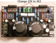
I've attached a picture of it. I want to change the voltage divider to use it as a 40 watt amp, but can't seem to figure it out. It would seem that the resistor indicated is the resistor between pin 3 and 9, but with my meter I don't get the connection to pin 9 on the other side of the resistor. Looking for the resistor to ground, I guess it is the 6.8K next to it, but again no reading to ground?
Anyone ever use one of these amps?
Board made in China. MK154.
I've attached a picture of it. I want to change the voltage divider to use it as a 40 watt amp, but can't seem to figure it out. It would seem that the resistor indicated is the resistor between pin 3 and 9, but with my meter I don't get the connection to pin 9 on the other side of the resistor. Looking for the resistor to ground, I guess it is the 6.8K next to it, but again no reading to ground?
Anyone ever use one of these amps?
Attachments
The datasheet for the LM3886 will have the schematic for you.
The feedback gain setting resistors dont go to ground.
The lower resistor goes through a capacitor to ground.
Why do you need to change the gain ?
Just dont turn the volume up so much.
Be aware that some chip amps have a minimum gain and with too little gain will oscillate.
The feedback gain setting resistors dont go to ground.
The lower resistor goes through a capacitor to ground.
Why do you need to change the gain ?
Just dont turn the volume up so much.
Be aware that some chip amps have a minimum gain and with too little gain will oscillate.
It is set at 4.5 and I need min. 24 i/o (27db). Max 1 volt input from source, 22v out. From what I can see the series FB resistors are 22K and 2k (why to resistors???). And yes the resistor to ground (and cap) is 6.8K + 2.7 (why two resistors???).
22k and 2k gives a gain of 11.
For gain of 24 try 47k and 2k
The two feedback resistors are a potential divider.
For gain of 24 try 47k and 2k
The two feedback resistors are a potential divider.
To be clear the series resistor is 24K (22K + 2K) and the resistor to ground (with cap) is 6.8K (actually 6.8K and a 2.7 ohm). It looks like if I change the 6.8K to somewhere between 1.1K and 1.2K, I'll have what I need.
The cap has markings I don't understand, but the board is marked 473. It's a very small boxed cap, to small to be an electrolytic, so it think it is a .047uF. Seems like this should be something like a 470uf, to set the low freq cutoff of the FB loop.
The cap has markings I don't understand, but the board is marked 473. It's a very small boxed cap, to small to be an electrolytic, so it think it is a .047uF. Seems like this should be something like a 470uf, to set the low freq cutoff of the FB loop.
473 = 47000 pF, 47 nF, .047 uF
Check on line, maybe I made a mistake.
And try putting a multi turn preset to fine tune your settings.
Check on line, maybe I made a mistake.
And try putting a multi turn preset to fine tune your settings.
- Home
- Amplifiers
- Chip Amps
- Schematic help