Dual 621 motor issue

I have a newly acquired Dual 621, when moving the auto play lever to ‘play’, The strobe light illuminates, but the motor does not start. When I spin the platter manually, the tone arm cycles properly, so no issues there. I assume this is a capacitor issue. I can solder ok, I have replaced caps on speaker crossovers, but I don’t know how to troubleshoot the power supply issue here.
Any help appreciated!
Thanks

Baxandall diode? AB quasi-complementary amp from 70' s

Hi. I was changing capacitors of an old amp from the 70's and I damaged two diodes and broke them.

If I'm not wrong this is a class-AB amplifier in quasi-complementary configuration. I've attached the schematic.

The diodes I meant are named ZE 2 in the schematic. I've never came across that symbol before.

I found the datasheet of the ZE 2:

https://www.web-bcs.com/pdf/Jn/ZE/ZE2.pdf

It says Uf = 2.0v ... 2.3v

Is that Uf the voltage drop? Or is it a zener diode and that Uf means the breakdown voltage? I would say the former but I'm not 100% sure.

My diode didn't look as the ZE 2 at all. It looked like a old silicon diode. Black and a bit larger than a 1N5817.

After some research and read about the Baxandall diode I would say that the symbol in the schematic means "three diodes in series". The voltage drop across the diode is 1.7v so the maths work here.

In my board there were just one diode per channel and not three. I could read 2V1 in the diode.

With my little knowledge I would say that I need a voltage drop around the 1.7v and I'm in business, but I wanted to share my thoughts just in case I'm wrong and hopefully to learn something.

Even if I'm right it feels weird that the schematic says 1.7 voltage drop and the specified ZE 2 diode has a 2.0 - 2.3 forward voltage...

Cheers!

Attachments

  • HS 51 SM-07.jpg
    HS 51 SM-07.jpg
    497.6 KB · Views: 436

8x Large Aluminium Heat Sink from England - Lots of flat space for device, power amp

Taken from power amplifiers. Approx. weight I think is 1.76kg each, 414mm long by 112mm high by 35mm thick, two milled flat areas for mounting devices which run the full length of the heat sink. Lots of slots for screw fixings etc

Purchased used on ebay and unused for an amplifier project which I have since changed my mind on and am buying a pre-built chassis.


s-l1600.jpg


s-l1600.jpg


s-l1600.jpg


s-l1600.jpg


I could post out to Europe but would prefer England
asking £22 per sink
They are also on ebay for a little more, I am happy to sell there if better for you

Thanks

denon cd player dcd485

this wont spin discs ive checket the usual suspects belt,lens clean ,
laser does the usual shuffle and with my camera was able to establish it works so i tested the spindle motor with ext supply its good .
so down to basics the check supplies.

+5v and -5v are good BUT the+8v and -8v are both +12v and - 12?
im wondering if during production they used a different centre tap tx

i will enclose cct

i entered the service mode and went through the various tests

so now im stumped

Let's Build: DIYSG New HTM-12 (2020): Build Log

What's up guys! I'm posting my first build here. I hope you'll enjoy the ride 🙂

Speaker Kit being built: Denovo Audio HTM-12

5/14/20- Received 1 out of 2 packages today. Unboxed Items and took photos for you guys.

Initial impressions: Words can't describe the precision and build quality of the flat pack kit. I couldn't build a better enclosure. Everything fits together so well, it stands on its own dry-fit. The MDF used is premium "CARB-2 compliant" MDF and lighter than normal (imho this is a good thing) and doesn't have that nasty MDF smell.
12" Woofer is surprisingly light due to its Neo magnet. I wasn't expecting the waveguide to be this thick and solid. The build quality of everything is like german precision engineering combined with the best aspects of rugged Russian and American durability. Everything screams quality. I was smiling ear to ear unboxing these.

Day-1 Pictures along with comments here: DIYSG HTM-12 (2020) Kit - Album on Imgur

(Edit) 5/15/20- Day-2 Pictures along with comments here: DIYSG HTM-12 (2020) Build, Day Two - Album on Imgur

Tannoy PBM 8 II

Many people still use the old Tannoys monitors from the PBM II series, and is very difficult to find information about them on the net. In this thread I will share some info I got in the past and is open to share more about them.

I have a set of PBM 8 II (mk II) not used as monitors, buit as room speakers, and think they still are very worth while, clear and transparent at low or medium power levels.

This speakers (Tannoy PBM 8 II) are Canadian made (not British) because Tannoy contracted a well reputed Canadian speaker supplier named API to produce them under Tannoy specs. (API=Audio Products International, same manufacturer of Energy, Mirage, Image, Athena Technologies and Sound Dynamics commercial brands, now owned by Klipsch). Tannoy PBM 8 II are two way passive studio monitors with a 1" tweeter and 8" woofer, with a rear ported (bass reflex) mdf well built cabinet, but with a cheap grey vinyl finish.

Tweeter: PBM 8 II uses a VIFA D27TG-45 (old P/N PL27TG45). Today the replacement part is the VIFA D27TG-35-06 chinese made. The differences beetwen them are only in the front plate dispersion axis external form, being the D27TG-45 some how bulged and the D27TG-35 completely flat. I think This tweeter was one of the first ones in the market (20 years ago) offering a low resonant frequency (fs 750 Hz). Specs of this tweeter are easily found on the net.

Woofer: PBM 8 II uses an API (Athena) 5DR/61047. This is a 8" injected Polypropylene molded cone with a nitrile rubber surround and 1" voice coil 4 ohm woofer. This kind of drivers (Poly cone + rubber surround) usually have a low fs (near 30-35 Hz) and if not abused lasts almost forever, unlike paper cone + foam surrounds (except for the surround glue, that dries out in dry places). Specs for this driver are not easily found because was a driver made for Tannoy and not for sale as individual or commercial woofers. Then, parameters have to be measured.
However, this woofer is very very similar to others used in Athena speakers like the well known Athena AS-F1 (woofer part number 5DR/61098), Sound Dynamics R-515 (woofer part number 5DR/61041) and others coming from the same manufacturer. If you need a direct replacement woofer you can look at "Orange County Speakers" as they still today have original replacement parts.
If you only want a cheap direct replacement woofer (compromising quality, of course), you can use an MCM 8" part number 55-1190 for $13

Poly cones with rubber surround woofers often achieves a good freq. response at lower frequencies, but tends to be less clear in their upper end. Maybe that's why Tannoy selected the tweeter with a low fs (750 Hz) and put the crossover frequency at 1.9 kHz. The tweeter at it low frequency crossover point works very well under small or medium power demands, but begins to be less clear at higher power or spl. The speaker supports bi-wiring and have relative small dimensions (H 402mm, W 277mm, D 273mm).

Attachments

  • Tannoy Brochure.jpg
    Tannoy Brochure.jpg
    793.3 KB · Views: 1,580

Multi tap OPT 2, 4, 8, 16 Ohm...

Hi!

Maybe you got some experience and tips on this...?

My speakers are 4 ohm.
The amp i 300B SET.
The OPT have 4 secondaries in series giving taps 2, 4, 8, 16 ohm...

Fig:
----------- 16 ohm
sec4
--------+
--------+-- 8 ohm
sec3
--------+
--------+-- 4 ohm
sec2
--------+
--------+-- 2 ohm
sec1
----------- GND

Since my speaker is 4 ohm, I will not use 8 and 16 ohm tap...
Is it benefitial/tweak to disconnect sec3 and sec4 (just use sec1+sec2 in series to get 4 ohm) or should sec3 and sec 4 be "playing" as load...?
I only have one (+-) speaker connector on my amp...

Best,
Tom 🙂

Buffalo IIIse help needed

Hi all, I bought a readybuild Buffalo IIIse dac and just don´t get any sound out of it. It consist of:

(1) Buffalo-IIIsePro32 (ES9038) 2-Channel DAC Module
(1) AVCC-SR Dual 3.6V Series Regulator Module
(2) TridentSR 3.3V Series Regulator Module
(1) TridentSR 1.3V Series Regulator Module
[1] Mercury v1.1 Kit plus [1] Placid HD BP Power Supply Kit
[2] LCDPS
[1]4:1 Mux/Demux Digital Switch Kit
[1] 4-Position Selector Switch Kit that Connects to the 4:1 Mux/Demux
[3] Transformers

extras
[1] Raspberry Pi Model 3 [1]Touch Screen

I have tried both the SPDIF and Raspberry Pi whithout luck. One LCDPS Powers the RPi + touchscreen an one Powers the dac, both 5.2V. The LCDPS have a hard time in driving the touchscreen, I have to use a separate Power for that.

I would very much appreciate some guidance in troubleshooting. For example if there is a voltage drop to the dac.
TIA

Attachments

  • 20200105_135558 (1).jpg
    20200105_135558 (1).jpg
    1 MB · Views: 391

LED light bulbs

Has anyone calculated savings compared to Incandescent bulbs?

I recently bought a box of 12 100W 5000K 1500Lumen bulbs off Amazon to improve the lighting in my house. At near 70 years I have difficulty seeing without lots of light.

I measured the power consumption and did a rough comparison to 100W 1000Hr life bulbs.

It looks like over a 1000Hr life of the incandescent bulb, the LED saves about $17 at a presumed electrical rate of $0.19/KW-HR (11.5W LED consumption). Given that the 25000 hr life is inflated, and using 10,000hrs instead.

I also bought some 200W equivalent 3000Lumin 5K temp bulbs that actually measure 23W consumption.

Isn't technology great?

Hifonics Zeus vIII Power supply issues

I have this amp in for repair that the power supply MOSFETS were shorted.
Removed dead MOSFETS, checked for drive. Had good drive. Replaced all the MOSFETS and checked for proper drive, and don't get proper drive.
Attaching picture to show current drive.

Also this amp has modifications done from a previous repair. Has anyone seen this before? The TIP transistors are attached to the TIP35 regulator transistors.

Attachments

  • 20210212_130803.jpg
    20210212_130803.jpg
    790.2 KB · Views: 142
  • 20210208_112718.jpg
    20210208_112718.jpg
    865.3 KB · Views: 179
  • 20210208_164142.jpg
    20210208_164142.jpg
    1,016.2 KB · Views: 162

Why is everything a cycle of 3? Or is it?

Is this something to consider after how many years of acoustics and speakers and the relationships of things to quarter wavelengths, pipe closed end harmonics, thermo versions of ‘pipes’ as motor generators of a heated and cooled on a pipe at a point offset by 1/3 its end?

The AC cycle,(everything with odd numbered harmonics maybe?, the phase of an offset driver at 1/3 down a ‘pipe’ or the use of 1/3 the opposite sides pipe as the length of the otherside to tube with if the phase is to be such that it couples(or so it seems in almost anything i try to sim or build or both?

Its no coincidence right? Or is it just the result of the inevitable nostalgic but silly idea and no more than ‘cosine and sinewaves at intervals of 30/60/90 to pythagoreum in a rotating of 1/3,2/3, 3/3... a circle..?

I feel dumb asking this. As if its a well known thing and im kinda overthinking its relevance to an assumption the qw designs or half of a wave(?) or non of it, are the ideal ways to cut and apply (in 3rds, as an offset if wanted to get ‘extra, thats there anyhow, but looks like ‘extra’ if comparing wide to tall in a response in subwoofers?

This idea might be best shown as ‘offset driver TL, and ‘compound horn’? One is 1/3 the other, and that results in a extension of the top area of BW it seems, and exactly how to donit hivers on the straight pipe sized and applied as 1/3.

this inside the speaker if a pipe, is also the ways to couple them within 270 degrees of the top section of the circles circumference.

I thihght that was obvious, but then i realized i was only used to umit, not so much that i had ever truely witnessed the use of another? My iffset drivers and paraflex, etc all get simmed. I never had ro ‘figurevout much of ‘why’ it was always in the right spot and thanks to David Mcbean, and /or Martin King, its pretty easy for anyone to do this?

But i just realized(?)!!!??

I have never ever looked at the other, or at the squiggly shape that shows up in the area of ‘junction’ in horn response...where two outputs or the dead end reflected of itself or seperates off the opposite side of a cone converge at or before exit?

Can i find these things by making them? And what will there be on a pressure gage and a mic, REW, and test tones specific to the pipe?

i have a lit of questions to which i intend to ‘look’. But where and what im
Not sure? But im going to start with thus OD TL... made to drag a mic and pressure sensor(?)around inside by a magnet on the other side of the lexan as shown

Attachments

  • 111DC765-3F1F-414D-A4A5-09111B5AAE9D.jpg
    111DC765-3F1F-414D-A4A5-09111B5AAE9D.jpg
    587.6 KB · Views: 175

Dynaco PAS 3X Re-Build

This is my first attempt at re-building an electronic component. It was partially inspired by the late Bill Thomas over at audiocircle and his PAS 3 and SCA 35 projects which he very meticulously documented. I've done some minor repairs in the past but not anything of substance.

My goal is to restore this PAS 3X with minimal if any mods. The exception is the replacement of the selenium rectifier with a pair of diodes as recommended by Curcio Audio Engineering, but I'm open to other options if anyone has any suggestions. Again, I'd like to keep this PAS as close to the original design as possible. I have a couple of other PAS preamps that need work and if all goes well here, will attempt to bring them back to life and with the help of this forum, hopefully improve upon the original design.

So, with a little extra time on my hands yesterday and today, I completely stripped the preamp of all of the gloopy solder and spaghetti like wiring from the chassis and got everything cleaned up.

All of the pots and slide switches were cleaned with CRC Contact Cleaner. Once the unit is assembled, wired and soldered, I will give them a shot of Deoxit to make sure everything is lubricated. The two selector switches were cleaned with denatured alcohol and a toothbrush. Again, I will Deoxit the contacts after the soldering is completed. I will then grease the detents as well. I'm doing it in this sequence because the Deoxit tends to drip.

Attachments

  • pas 3x 1.JPG
    pas 3x 1.JPG
    715.6 KB · Views: 434

Critique my soft start

I've been reading this treasure trove of soft-start info; Soft-Start Circuits

I'm using a 800VA Transformer (output 45-0-45V AC) with 22400uF caps, Input is fused before this board

250k trimpot gives ~0-2s delay adjustment till relay kicks in a removes inrush limiters from series with torroid primary.

The reset time should be quite low - need to measure once breadboarded
The inrush limiters should stay fairly cold - so should continue to provide protection on AC dropouts
They also won't catch fire compared to using wirewound resistors if the relay failed to kick in.

Resistance calcs for inrush limiting;
I = VA / V
I = 800 / 230 = 3.48A
R = V / (Ix2)
R = 230 / (3.48x2)
R = 33 Ohms

Primary parts;
https://mouser.com/ProductDetail/709-IRM02-12/
https://mouser.com/ProductDetail/653-G2RL-1A-E-DC12/
https://mouser.com/ProductDetail/995-SL15-10006/
LM311P Texas Instruments | Mouser

https://www.ti.com/lit/ds/symlink/lm311.pdf

I haven't played with a LM311 - datasheet says it can drive 50ma which will handle the relay coil fine

Any advice on layout improvements?

Attachments

  • Schematic_inrush-limiter_2021-01-25_11-55-48.png
    Schematic_inrush-limiter_2021-01-25_11-55-48.png
    163.1 KB · Views: 486
  • PCB_PCB_2021-01-18_18-24-19_2021-01-25_11-55-26.png
    PCB_PCB_2021-01-18_18-24-19_2021-01-25_11-55-26.png
    49.2 KB · Views: 481

Help!!! Tubes4Hifi SP14 noisy

Anyone have the same issue? Any takers? I built a Tubes4Hifi SP14 preamp with the Khozmo digital controller about a year ago. I paid in my opinion a lot of money for this thing including extras for upgraded parts. Since I built it I’ve been battling a slight hum and buzz. So fricking annoyed at this point. Over the past 11 months, I’d work on it, get frustrated and come back to it a couple months later and here we are today. I’ve worked on and off with Roy from T4HF quite a bit in the beginning and have tried just about everything. I’ve changed tubes which made the noise more tolerable but it’s not right. The SP14 feeds a pair of M-125 monoblocks from VTA Bob Latino that I also built. I don’t feel the issue is with the monoblocks because they are pretty much totally silent when connected to my Bluesound Node 2 streamer. There is something isolated to this preamp that doesn’t play well with the monoblocks. Over the weekend I brought the SP14 down and tried it on another system which uses a Jolida JD1000 integrated amp which could be used as a straight amp in bypass mode. The SP14 preamp was pretty quiet. A quick description of the noise sounds like a guitar amp which the gain turn up. Would it be best to send the SP14 back to Roy and pay him to figure it out but I’m afraid he may not see the issue on his end and now I’d be throwing even more money at it. Any thoughts on where I can be picking up this noise and what can be done about it. Thank you in advance

Nakamichi PA-7II: Thermofuse in the potted transformer

Hi Everyone,

I purchased a Nakamichi PA-7aII power amplifier this weekend, which is a model I've coveted for many years...unfortunately the amp's first owner shorted the speaker outputs on this amp a few years ago, and it hasn't turned on since.

A local Tech diagnosed the problem with amp for the previous owner as being a burnt out thermo fuse; this would be an easy fix, except that device is located INSIDE the huge potted proprietary transformer. The Tech told the old owner that it would be necessary to physically chip away at the potting material inside the transformer to replace the thermo fuse, so he declined to perform the repair.

I did some basic testing and reviewed the service manual schematic with a Technically minded friend, and confirmed the thermo fuse is, and is located inside the transformer. Does anyone have any solutions on how to fix this problem? I'm assuming I can't just safely bypass the connection where the thermo fuse is wired into limiter PCB. Are there solutions that might help to dissolve the potting compound so I could get inside the transformer?

Any suggestions would be welcome!

Thanks,
Trevor

ecasound channel time allignment off by buffer time

I'm using ecasound for active 3-way filters based on Richard Taylor's work.

Using the command below the mid and tweeter are delayed from the woofer by the length of the ecasound buffer. It sounds really weird with buffers approaching 200ms.

Code:
ecasound -z:mixmode,sum -x -z:nodb -b:ecasound_buffer_size 
-a:pre1 -f:16,2,44100 -i stdin -pf:pre1-3way.ecp -o:loop,1 
-a:pre2,woofer -i:loop,1 
-a:pre2 -pf:pre2-3way.ecp -o loop,2 
-a:mid,tweeter -i:loop,2 
-a:woofer -pf:woofer.ecp -chorder:1,2,0,0,0,0,0,0 
-a:mid -pf:mid.ecp -chorder:0,0,1,2,0,0,0,0 
-a:tweeter -pf:tweeter.ecp -chorder:0,0,0,0,0,0,1,2 
-a:woofer,mid,tweeter -f:s16,8,44100 -o:stdout

Removing use of loops following Charley Laub's example makes the problem go away.

Code:
ecasound -B:rt -z:mixmode,sum -z:nodb -b:ecasound_buffer_size  
-a:woofer,mid,tweeter -f:16,2,44100 -i stdin 
-a:woofer -pf:woofer.ecp -chorder:1,2,0,0,0,0,0,0 
-a:mid -pf:mid.ecp -chorder:0,0,1,2,0,0,0,0 
-a:tweeter -pf:tweeter.ecp -chorder:0,0,0,0,0,0,1,2 
-a:woofer,mid,tweeter -f:s16,8,44100 -o:stdout

So for now I'm happy. I'm just curious what I'm doing wrong with the loops in case I need them in the future.

Some application specific stuff:
I'm using stdin and stdout to get data in and out because my multiroom implementation requires direct control of the soundcard to extract the needed timestamp information. This ultimately goes to a 7.1 receiver over HDMI which is why there are 8 channels. Center and Sub are the two unused channels. Using small buffers makes the problem less perceptible, but doesn't fix the problem. It also seems to extend processing time which causes other issues for me. I haven't even begun to actually measure the drivers yet, that's next.

Thanks,
Mike

Reviving a dead sub amplifier

Hello,

my Boston MCS-95 no longer functions, standby LED is off, no sound. The fuse is fine, and even the post rectifier stage ~350V at the half bridge driver appears to be good. Found an old post about the 18V zener being blown, but the replacement didn't fix mine.

So I could scrap the whole thing and buy a new one, but what fun is that?

I have the full schematic, background in EE (microwaves mostly) and plenty of test tools.

Any recommendations of where to start to understand these class D amplifiers? a

Thanks in advance

Strange output filter on Dayton/sure/wondom tpa3116 board

Hi tpa3116 gurus,

I’ve got a nice collection of different cheap tpa3116 boards and none of them are that different than the reference design in terms of output filtering. Except, naturally, the ones i want to use for this project.

These sure/wondom/dayton boards using the tpa3116 (i have the dayton kab-1100 and the dspb-250) use a strange filter with a diode rectifier in it. I have scoured the internet to find a similar circuit and i think my amateur EE skills have reached their limit.😕

I’ve retraced the circuit to the best of my ability (some of these boards are more than 2 layers) and overlayed it on the picture. The picture here is the simplest of the boards, but they all have the same architecture.

What do you think? I’m looking to get rid of the ceramics in the signal path and potentially increase the size of the inductors (all of my other boards have 330 or 220 inductors)

Any references to how these type of filters work would be great. I want to learn as well as make these amps reach their potential.

Attachments

  • A97AFC79-D308-42CC-9653-8F1E93FA1E7E.jpg
    A97AFC79-D308-42CC-9653-8F1E93FA1E7E.jpg
    431.4 KB · Views: 139
  • 7687D5A1-F13A-4B0A-AC78-209ED6C1FE5A.jpg
    7687D5A1-F13A-4B0A-AC78-209ED6C1FE5A.jpg
    860.9 KB · Views: 140

Is there an appetite for non-discrete solid state DIY headphone amps anymore?

More of an discussion piece, but just wanted to generate some thoughts. Sorry for the long post. As a precursor, my affinity between subjective and objective analysis lies very much in the middle. I had a decade long break from DIY audio (Warren Young and Ti Kan's designs were fresh off the block back then) but I think I have now caught up back to speed. Henceforth, this post.

With the development over the past decade of better solid state ICs, there has been an overall drive towards objectively brilliant commercial amps, resulting in JDS (Atom, Element), Topping (A90, now single-ended L30), and THX AAA-based amps dominating large sectors of the market. The ASR.com or "Audio Precision" effect.

Looking at these design topologies, they all use implementations of ultra low-noise opamps (NJM2068 in Atom, OPA1612 in A90) combined with ultra-high feedback loops / nested topologies and buffers (LME49600 in JDS amps, TPA6120A2 "Nested Feedback Composite Amplifier" quad-channel in Topping's A90).

Correct me if I'm wrong but ever since the Objective 2, there does not appear to be many that have made a significant impact in SS-IC amps in the DIY arena. I'm aware of The Wire but haven't seen much more progress for a while. There is also a PCB layout from Pavouk of LME49720 gain + LME49600 DC servo, based on TI's own evaluation board schematic, but again this hasn't really taken off in DIY circles. A rough and readily conjured chinese PCB implementation of this is available for £3 at your favourite auction site. I haven't found any complete non-modular designs which surpass Objective 2's objective qualities.

Then there is Tom's incredible Neurochrome HP-2. However, this is closed source with no schematic available. This is no criticism though, as the design is absolutely first class, with obvious and understandably huge amounts of effort being put in. However, I would classify this more as a commercial implementation.

I'm curious then, why more ultra-low noise solid state IC-based high-feedback designs haven't been pursued any further in open source discussion? Perhaps we've reached a nadir of DIY performance? ASR would disagree, but striving for inaudible gains might not be in the DIY ethos? Perhaps it's a limitation of measurement, given that commercial amps are approaching the noise limits of $25k testing equipment? Are commercial implementations simply too good in value versus performance that it hasn't been worth it? Perhaps DIY audiophiles prefer deliberate sound signature modification through discrete designs? Maybe, I am simply looking in the wrong place and need enlightening?

I really don't know the answers. What are other people's thoughts? Clearly there have been some great discrete DIY amplifiers born from these forums recently and elsewhere, but what is happening to IC-based development?

Alesis RA150 burns power resistor

Hi All,

I am new to audio electronics tinkering and hope my diyAudio participation proves valuable to others as well.
Jumping right in: My recently repaired Alesis RA150 worked for 2 wks then quit, again burning out the power resistor.
What happened: Heard a “click” thru spks, volume increased on its own, “searing” noise thru spks, sound died amid smoke.
What I found: 1. Mains Fuse burned; 2. R401 (470/2W) burned; 3. C403 (220uf) bulging at top but testing normal with analog vom; 4. Z1 (15V) shorted.
Repair Status: Changed those 4 parts and reconnected LED indicator circuit, Driver amps and Pwr amps to Pwr Supply board one at a time.
Bench running at low volume for a couple hours now. DC at spk terminals: Rt – 0.1mV Lt – 0.5mV
Question: What else should I check and/or replace before putting amp back in service? Previous fix included change of all el’tic caps except main filters and 2 in the LED circuit. Schematics can be viewed here http://forum.vegalab.ru/attachment.php?attachmentid=75690&d
Big thanks.
Mort

Repair of Alesis RA150

Hi All -

I recently agreed to help a friend try to revive an Alesis RA 150. After getting a better understanding of the symptoms, a quick review of the service manual, and a YouTube video session - I was convinced I could take on a repair (vs. just fixing things I had screwed up in my builds). 😀

It seemed all it needed was a simple replacement of RL-1. Oops.

Summary -

Original Symptom - Amp would go into protection and not leave protection upon power-up. Originally intermittent, then permanent.

Original Diagnosis - Bad RL-1

Replaced original RL-1 with - NTE Electronics R25–11d10–12

Current symptom - Does not power up. Does not go into protection. Oops.

I feel 90+% confident that the relay swap went without issue mechanically. Removal and replacement were not problematic. No lifted pads or traces. Clean solder work.

I am not skilled enough to do a full diagnostic based upon the schematics. I have attached the service manual. RL-1 is in the power supply section on page 8.

Any assistance with a brief set of initial test points / troubleshooting steps would be greatly appreciated. Before I took on the work, we agreed that it was okay if I bricked the amp since he was going to toss it anyway. Now it's become a matter of pride 😀 I'd love to get it working for him, particularly after I said something to the effect of "Oh, it's just a simple relay gone bad. I can fix THAT". 😀

Thanks in advance for any help provided. Attached is the service manual.

:cheers:

Attachments

JBL 2226H 30 hz "horn" i built

An externally hosted image should be here but it was not working when we last tested it.


An externally hosted image should be here but it was not working when we last tested it.


An externally hosted image should be here but it was not working when we last tested it.


An externally hosted image should be here but it was not working when we last tested it.


An externally hosted image should be here but it was not working when we last tested it.


An externally hosted image should be here but it was not working when we last tested it.


An externally hosted image should be here but it was not working when we last tested it.


An externally hosted image should be here but it was not working when we last tested it.


An externally hosted image should be here but it was not working when we last tested it.


An externally hosted image should be here but it was not working when we last tested it.


An externally hosted image should be here but it was not working when we last tested it.


An externally hosted image should be here but it was not working when we last tested it.


An externally hosted image should be here but it was not working when we last tested it.


An externally hosted image should be here but it was not working when we last tested it.


An externally hosted image should be here but it was not working when we last tested it.


An externally hosted image should be here but it was not working when we last tested it.


An externally hosted image should be here but it was not working when we last tested it.


An externally hosted image should be here but it was not working when we last tested it.


An externally hosted image should be here but it was not working when we last tested it.


An externally hosted image should be here but it was not working when we last tested it.


An externally hosted image should be here but it was not working when we last tested it.


An externally hosted image should be here but it was not working when we last tested it.


An externally hosted image should be here but it was not working when we last tested it.


An externally hosted image should be here but it was not working when we last tested it.

What determines the frequency range of a loudspeaker?

Dear diyAudio forum,


I’m browsing for a 15” driver and I’m finding that they can vary quite a bit in their frequency range, I find this a bit surprising.

How come two same-size drivers can have a different frequency range, i.e. one has 50-4000Hz while the other has 38-1800Hz?

What determines the low and high cutoffs if they’re the same size?


Many thanks,
Simon

Replacement drivers for Mission 701?

Hi, I have a pair of Mission 701 speakers, and one of them has developed a rattle when playing certain low frequencies. It's particularly noticeable when watching movies. The affected speaker got pushed off its stand once or twice by children (now firmly mounted on the wall), and I guess there's now a misalignment somewhere in the driver.

So, if I wanted to replace the affected driver, does anyone have any suggestions for similar drivers that I could swap in? I'm guessing that I'd probably need to replace the one in the other speaker too, unless I can source an identical unit to the broken one?

Thanks for any ideas!

Ocean Way Pro 2A drivers

At Florida Audio Expo today I was totally blown away with the sound of the Ocean Way Eureka speakers. As far as I can tell, these gorgeous $18k per pair speakers have exactly the same drivers as the Ocean Way Pro 2A studio monitors which cost $1800 per pair but are self powered and matt finished. I am dying to aquire these drivers and see what could be acomplished in a DIY build using them. Does anyone out there know what they might be?
A link to the designers discussion of them, including good video closeups of the actual drivers is: YouTube
Any help would be appreciated!

Best,
Jay

Magnetic shielding with aluminum

I have been digging around in the archives looking for some information on magnetic shielding with non ferrous materials. I saw varying opinions about its effectiveness. Looking for info on the internets in general I came across this paper

http://www.chomerics.com/products/documents/emicat/pg192theory_of_emi.pdf

Reading through it seems that aluminum can be an effective magnetic shield if it is thick enough. Playing around with the nomographs at the end it looks to me like .25” of aluminum is about as absorptive as .009” of Mu Metal (about 6dB of absorption losses at 60 Hz) the reflection losses look to be about 20 dB but I gather these are to be ignored if you are only worried about the magnetic portion of the wave.

Does anyone have practical experience or a better grasp of the math that confirms what I think I see?

Thanks,
Marty

Laney Supergroup MK1 restoration

So, yesterday I picked up an early 1970´s Laney Supergroup MK1. The dude gave it away for free because he was moving and was tired of storing it. I got the info that the amp powers up but it doesn´t make any sound. Well let´s see..

I took some photos outside that shows the amp has been stored quite well. It has a couple of really small dents in the corners but the vinyl is in very good condition. I also took the chassis out and set it up for some closer examination. Looks like this beast is pretty much original and I got some serious replacement work ahead. I will print out the schematics tomorrow and start taking some measurements. Luckily the inside are overall pretty clean so it´s not too had to follow the schematics.


I´m not powering it up. I´m thinking I´ll first go through measuring the coils of the transformers to see if there are any shorts. Also checking shorts in the tubes, couple of the power tube sockets feel a little loose.

I posted this thread because I know someone has some insight reagarding this particular amp and possibly can see the condition of this unit in a different view. Also any discussion regarding this amp is welcome.

K

Kii Three / D&D vs. PSI Audio actives - DSP vs. analog crossover

This is not exactly a DIY question, but since this forum is frequented by people who have knowledge and experience in speaker design and measurements I would like to ask for some opinions on the following speaker designs.
I will certainly make effort to hear speakers mentioned in my questions.

I am interested to hear about experience with and opinions about 3-way speakers employing digital (DSP) active cross-over (examples being Kii Three and D&D8c) vs. 3-way speakers employing analog active cross-over (examples being PSI Audio A23-M, ATCSCM50ASL).
If you look at those examples, PSI Audio A23-M is using propitiatory tweeter and midrange drives developed in house, with propitiatory amplification using unique technology such as Adaptive Output Impedance error correction feedback system which according to them allows for superb control of excursion. They also do phase compensation what is evident in impulse response and transients reproduction. All of this done in analog domain, what according to them is the proper way, not employing DSP. This certainly sounds like proper approach.

On the other hand, Kii Three does active cross-over in digital domain employing DSP. They also do phase compensation as well as cardioid dispersion pattern in low-mids and bass which is certainly beneficial, and their DSP processing seems to be very well done, what is all great, but on the other hand they use off-the-shelf drivers and amplification.

My thinking is that the two examples of DSP driven speakers would certainly be the ultimate examples of what could be achieved in quality sound reproduction if they employed higher quality electronics, for example not little switching supplies that feed everything, from DSP processor, to DA converters and amplifiers. Does this make sense, do you think that the design and objectives were exemplary but the execution is not that great due to many compromises to keep the cost down?
And it is probably not only the examples of DSP driven speakers, PSI Audio example probably has bunch or relatively noisy op-amps in its active analog cross-over powered by switching PSU that introduce lots of issues and they had to employ many to align phase.

So I am interested to hear how these compare based on actual experience and/or in lack of the actual experience opinions based on some sound engineering knowledge, and which approach (DSP or analog active) would degrade the signal less.

Building the TA-477 Kit Soundmaster ETI

Cruising eBay the other day I came across this interesting 120 watt Mosfet Amplifier kit. I placed my bid for a few bucks and won it! the 4 NOS Hitachi mosfets alone are worth several times what i won it for. Sadly there was only one and I seriously doubt i will find another so I thought it would be fun to build this as a General Purpose Shop duty amplifier.

I didn't know anything about these kits. but apparently this was from the Mark V era of kits? and I found a thread here on DIY that appears to be related.

https://www.diyaudio.com/forums/solid-state/134481-eti-477-resurrected.html

there are several mods mentioned in this thread and I thought a review of them and any others to help make this a solid reliable amplifier might be in order. your input is welcomed.


Zc

Attachments

  • 20191103_122826.jpg
    20191103_122826.jpg
    840.8 KB · Views: 717
  • 20191103_122740.jpg
    20191103_122740.jpg
    794.9 KB · Views: 923
  • 20191103_122723.jpg
    20191103_122723.jpg
    833.4 KB · Views: 710
  • 20191103_122835.jpg
    20191103_122835.jpg
    764.8 KB · Views: 583
  • 20191103_122844.jpg
    20191103_122844.jpg
    860.4 KB · Views: 563
  • s-l500.jpg
    s-l500.jpg
    30.7 KB · Views: 356

Opamp change CD player

Ive upgraded my Marantz CD75MK2, CD50SE (bought that one modded), and Philips CD850MK2. used LM4562 in all with great results. I think they make LM4562 with the pins? Other contenders to use? they are smd type

I am upgrading the caps in my lower spec Technics SL-P350, and want to change the opamps in it and my higher end Techncis P990. I assume they are dual amp opamps.

----------
P990 service manual is a bit confusing , i know the IC amplifer is opamp, not sure what buffer amp, should be changed also:scratch1:
rihug7.jpg

Is it possible to fix my Grant Fidelity TubeDAC-11?

I have a Grant Fidelity TubeDAC-11 and about a year ago the DAC portion of the amp stopped working. I remember hearing a subtle pop and that was that, no more audio coming out of the amp. It happened at the same time my wife stepped on the USB cable going from my laptop to the DAC but that could just be a coincidence. Everything else still appears to work, the analog in passes the signal through the amp just fine, so I am guessing a chip died. My question is it possible for me to replace the DAC chip on my own? Could it be a different chip that needs to be replaced? If it is at all possible, I'd like to give it a try, it bothers me that this DAC is going unused. I don't have a heat gun but I've watched a few YouTube videos that show how to remove and replace a chip using a lot of flux and a soldering gun, they even make it look easy (ha!). Also, I can't find a schematic anywhere.

Am I wasting my time with this?

Thanks in advance for any advice anyone might have for me!
-Brian

Here's a photo of the board. I can take more and better pics if they would be helpful.
5Nn122I.jpg

FS: 25% off Purifi Audio EVAL1 Amp & Hypex SMPS3KA400 Power Supply

Sale:

Brand New (Never Touch) Purifi-Audio EVAL1 Amp = 5968DKK/each original price (x3)
Brand New (Never Touch) Hypex SMPS3KA400 Power Supply = 250Euros/each original price (x 2)


After 25% off
EVAL1 = 4476DKK = 715USD/each
SMPS3KA400 = 187.5Euros = 225USD/each

Please fill free to PM

Attachments

  • 1.jpeg
    1.jpeg
    237.8 KB · Views: 536
  • 2.jpeg
    2.jpeg
    217.4 KB · Views: 543
  • 3.jpeg
    3.jpeg
    194.4 KB · Views: 539

Cyrus one repair

An old topic, I know, but what are people using to replace the buv28 transistors when repairing their amps? I've been reading articles and forum chat for a few weeks now.
I assume most, if not all on eBay might be fakes? I know there's been lots of suggestions for alternatives but most failing in one way or another to live up to the spec. of the originals. I wonder what the specialist repairers are using?
Had anyone got the definitive answer?

KRELL KTC

does anyone have the schamatic for a krell ktc preamp .i changed out caps on the power supply and one of the voltAGE selection sws popped . i can see anything wrong visually and by testing . im not sure what way sws go in now but pics tell me its as it was . any schmatic would be helpfull . if not monay ill call krell .
thanks in advance

Alpine MRX-M50

Hi All,

I am working on an Alpine MRX-M50. Does anyone have the service manual on either the MRX-M50 or the MRX-M100, that should be very similar? Perhaps someone else have also experienced the issue I am seeing.

Got the amp with missing power terminal screws. Amp tested fine on low power, but once I got terminal screws installed and higher power connected, it works for a few seconds and then shuts down, with and without a load connected.

None of the outputs are shorted and both channels produced clean/clear audio, before it shuts down. The power supply section seem to use pin4 of the TL494 as protection input, with a PNP pulling it up after a few seconds.

Any advice/help?

Without the manual, trouble shooting the protection circuit is proving difficult.

Attachments

  • IMG_4602_C.jpg
    IMG_4602_C.jpg
    817.5 KB · Views: 78

High speed optocoupler for spdif isolation?

Hi everyone,

I need to isolate the spdif signal from a noisy source to a WM8805 transceiver. I have been reading that the toslink connections available nowadays aren’t able to do 192khz anymore. So that leaves me with ‘normal’ spdif.

Since my two boards are in the same enclosure, i was thinking to just use a high speed optocoupler to do the isolation. Something like this https://www.mouser.com/pdfDocs/Renesas_RV1S9960A.pdf

Do you see any issue with that? (Or is there a better solution?)

Ideally, i could also use this method to use a coax spdif from a computer

Group Buy Discount

We have a potential large group of people interested in purchasing the following parts

Binding posts

Cardas CCGR S Binding Post, Sonic Craft

RCAs

Cardas GRFA L RCA, Sonic Craft

XLRs

Cardas CM F XLR Chassis XLR, Sonic Craft

I don't have definite numbers as yet, it could be anywhere between 10 and 40, as a reasonable estimate.

Would it be possible to get some kind of group discount?

0.5 mm dia (24AWG) 9-way solid-core ribbon cable

I have searched extensively online, and on the forum, but cannot find this cable anywhere. Does anyone know where I could possibly source this ribbon cable. The pitch is 2 mm between cores. To my knowledge it was originally sourced from the UK - many years ago.

If I have opened this thread in the wrong place please move it accordingly - just don't see anything specifically for cables.

Thanks, Kevin

Picture of cable

Attachments

  • Solid-core ribbon.jpeg
    Solid-core ribbon.jpeg
    22.3 KB · Views: 77

Dynaco ST70 with new driver PCB.

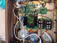
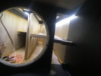
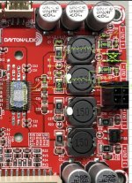
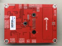
Hi, i have strip and cleaned a original ST70 using original PT and OPT.
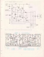
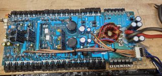
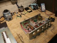
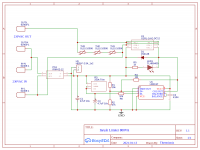
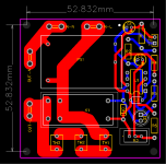
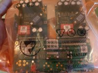
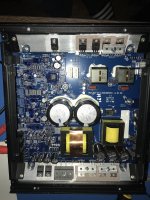
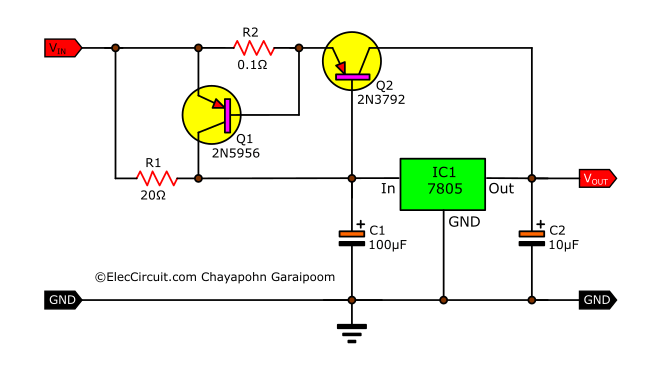
See the attached picture of the PCB circuit. All parts are new.
I installed the pcb and used 12AX7 and 12BH7A (12AU7)tubes.
I have +300Vdc to it, fonctions fine.
B+ of the amp is 400Vdc.

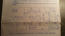
But i have trouble with the Dynaco ST70 with feedback loop.
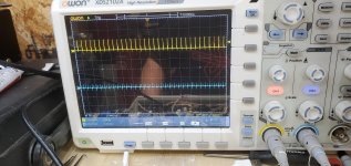
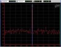
As is with the R7-C11(7,5Kohms and 220pF) feedback of the circuit, amplifier goes into oscillation, high pitch noise.

I did some experiementation on FDB circuit with this same configuration on other tube amps i built before a Scott 6L6 and a 6L6 Heathkit and got excellent results.

Without FDB the ST70 amp is stable as open loop, but low gain, and high distortion THD.
I have tried some different résistors value to find the point were it would remain stable. (changing the value of R7 to have nothing connected, and up to 17,5Kohms to have minimum FDB).

  • Add in serie with R7-C11 a 2,2Kohms = no high freq. Pitch noise, but on music transient i get oscillation.
  • Or add a 4,7Kohms= same
  • Or 10Kohms= no improvements, oscillation on high frequency transients.

These test i did used the C11 =220pF and did not changed it.

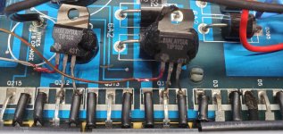
From there i did also tried a use the DynacoST70 classic FBD, directly connected a 1,5Kohms unstead of R7 and add at the screen lower EL34 a 500pF capacitor To the jonction of R9 -R5. On the 12AX7 cathode.
Still high frequency pitch noise once i ramp up B+ voltage to 400Vdc.

SO i kind of trying to swap tubes, but it is a non situation if in the future if you change tubes, it will go oscillation again, not a good idea.

So FBD loop is necessary, but tried to have more feedback, not correct, less feedback by adding series résistors.

All this is is from 16 ohms tap OPT.

Output tubes bias fine at 35mA each.

What do you think, so i try to change C11 for a different value 390pF?? 500pF??
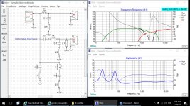
I haven't test the amp with square vawes signal as to haveit stable before i will tweak it for best waveform possible.

Thanks.

Attachments

Stabilovolt regulators?

Anyone have any experience with the interesting Stabilovolt voltage reg tubes? I think they were not allowed to be exported to the USA (it's an excellent German product) which may explain why I very seldom hear about them. ?
I see them on ebay for not so much, and they certainly look very interesting for getting several voltages out of a single bulb. I think the most common had 70V outputs, and several in series, so 70, 140, 210, and 280V outputs.
They are relatively large, but the neon ? makes for cool display.

Attachments

  • 20210206_105554.jpg
    20210206_105554.jpg
    443.9 KB · Views: 288
  • 20210206_105659.jpg
    20210206_105659.jpg
    561 KB · Views: 276

Crossover design - High sensitity tweeter...

Hi All

First post, so apologies if this is a stupid question.

Here is a tweeter I like the look of but it starts dropping off at 15k: https://www.morelhifi.com/wp-content/uploads/2019/12/ST1048.pdf

At 18k its about 88db which is what I'm aiming for

Is it possible to design a passive high-pass filter that leaves 15k onwards alone and just attenuate everything below 15k? I want to cross it over at 2k.

Cheers 🙂

Separate or shared quarter wave volumes for multiple drivers?

Ok, if we imagine we are building a single volume quarter wave for a MTM o TMM, we use the center between the two drivers as Zd.

But what about the Ariels. They have separate lines and they do not use Zd.

What are the weights of significance of using separate lines?

What if we build an MTM bipole (front + rear MTMs). What would make more sense if we have to use two separates lines overall?

Power transformers, which ones are good/quiet?

Got myself a pair of Noratel 160w 30 volt for one of my amps and they humm way to much! Both are the same though so can't say one is off spec so to say. They got a bit better once I tightened the screw holding them down but its still more than is ok.

Reading up on it here I understand all of them do humm more or less but these are very noisy compared to my other amps/power transformers.

Question, is there a consensus on here which make of Toroid transformers that are better/best in this respect?

Alternatively is there anything I can do to minimise this (other than baking them)?

All the other amps sit on the same powerline and are "mostly quiet".

"The Crocodile"

"The Crocodile" headamp

It is started a while ago, more like a joke. Attempt to show that with a pretty simplistic nested feedback loop concept and a bunch of NE5532 it is possible to achieve a 0.1ppm distortion level for 20kHz signal at 33Ohm load and couple of Vrms. I sort of achieved the goal, with an exception of a few "but". Of course one of those "but" was, as almost any early stage proto, it looked ugly as hell:
hq0qblq.jpg

Long story short, I managed to squeezed it into a 50x50mm PCB (sorry, no imperial units allowed!) to get PCBs for cheap from the Seedstudio. So, here it is. It is green, it is still somewhat ugly, and someone called it "a crocodile", so I decided - Crocodile it is 🙂
6t3mK0r.jpg

Although I didn't stick with 5532 this time. Tried some different opamp, to see how it goes.
There are some measurement results on a 33Ohm load. In case of the 20kHz signal, the output amplitude is 4VRms (+12dBVrms), for the IMD test it is mixture of two 2Vrms (+6dBVrms) signals.
It is not hard to make something better using the same number of opamps, but the moto was "as straightforward as possible" 🙂

Attachments

  • ha_55_40k_4vrms_.jpg
    ha_55_40k_4vrms_.jpg
    90 KB · Views: 2,860
  • ha_55_60k_4vrms_.jpg
    ha_55_60k_4vrms_.jpg
    90.3 KB · Views: 2,833
  • ha_55_80k_4vrms_.jpg
    ha_55_80k_4vrms_.jpg
    90.2 KB · Views: 2,795
  • ha_55_100k_4vrms_.jpg
    ha_55_100k_4vrms_.jpg
    90.7 KB · Views: 322
  • ha_55_imd_20k+21k_1_.jpg
    ha_55_imd_20k+21k_1_.jpg
    95.2 KB · Views: 379
  • ha_55_imd_20k+21k_2_.jpg
    ha_55_imd_20k+21k_2_.jpg
    74.7 KB · Views: 377

Restore or hot rod?

At the end of summer I picked up some (FREE!) AR-90, cabinets are 5-6/10 but can be brought back to life, drivers don’t appear to be blown but need surrounds on subs and mid-woofers. The surround kit just arrived so time to get cookin They obviously need crossover work so do I...

1.) restore them to originalish or

2.) install 4 sets of binding posts and 2 passive networks (1 for mid/tweet 1 for woofer/subs) along with a bypass switch so they can be bi-amped passively or quad amped with active dsp to each driver? Or?

12VDC options

I’m new to Class D and getting confused with all the chip options out there. I’m looking for an amp (board or built) that will operate directly from a 12V battery (13V range).

The plan is to take the system on the road this spring in an RV. Speakers are 6 ohm Alpair 12P so looking for something less than 50W. This will be fed from a MiniDSP. P-E sells a few options but not sure about the quality of some of their products. The Allo Volt+D caught my eye but not sure it will operate on 13VDC.

Thanks.....

Disadvantages of using L78XX/L79XX with current boost(MJ2955/2N3055)

Wondering why the use of L78XX/L79XX with current boost(MJ2955/2N3055) is not popular as a simple linear regulator for chip amps and such?

Circuits like this (showing positive rail)
increase-the-current-ic-lm7805.jpg


What are the reasons to shun these? Bad line/load regulation? Efficiency? For example a 15-0-15 200VA with the above configuration can make a good +/-18 V 5A power supply in theory.

I understand Opamp based finer designs with precise reference voltages have better line and load regulation. Is that the only reason?

Noise in guitar amp output that decreases heavily when I touch the guitar and ground

What you read above. It's a very simple amp - A gain block that goes into a diode clipper followed by another gain stage, some low frequency filtering and then power output using a class B output within a unity follower feedback loop. The amplifier itself works very well without any discernible noise (this is for headphones btw, so the noise would definitely be noticeable). But when I use the only >10V supply I have (It's a pretty crappy SMPS), it induces a lot of noise into the circuit. I've tried filtering it through a CLC filter, which didn't work well. I also tried a capacitance multiplier - didn't work well either. Strangely however, if I ground myself and then touch any metallic parts on my electric guitar, the noise drops noticeably. It doesn't go away though. I'd like to know why that is, it's very interesting to me.
I'd appreciate advice on how to fix the noise as well, but the above is what I'm really here for.

Rockford Fosgate T1500-1BDCP - No Gate Drive

Hi all,

Working on my RF T1500, seems to be an issue with the power supply card, I'm not seeing any gate drive. I've removed the card but haven't started measuring stuff yet but will start on that tomorrow. What typically goes out on these?

Does anyone have the schematic for this power board (1325-52873-06)? I have the schematic of a T1000BD that I'm referencing off of.

Also, is there a direct replacement for the LM339DG comparators? They seem to be obsolete.

Thanks

edit: after browsing around on here i've found out about quest components which have the LM339DG in stock 🙂

The Intellectual People Podcast - Founder/CEO Chuck Surack of Sweetwater.com

The inspiring story of Chuck Surack who started in a VW Bus and has grown Sweetwater.com to over $1B in sales. Chuck is a humble man who does a lot for music education on top of being a business leader in online music instrument and equipment sales.

Founder and CEO of Sweetwater.com Chuck Surack - YouTube

Attachments

  • sweetwater.jpg
    sweetwater.jpg
    150.5 KB · Views: 66

Building 2 way speakers with 4 woofers + 1 tweeter. Dynaudio 17w75XL

I got 8 dynaudio 17w75xl woofers. Pretty sure they are all 8ohm

I've always wanted huge midrange big stage speakers. Forward sounding
Classical , string music, piano.

I found a thread where another gentleman successfully designed a 2 way Cross over for 17w75xl + d260 tweeter
1)
I wanted to see if it's possible to use the same Cross over + similar tweeter but use 4 17w75xl drivers in series + parallel (2 in series) then 2 pairs in parallel

2) wanted to see what are the issues If I position drivers in square configuration with tweeter in the center of all of them as opposed to conventional vertical array of woofers with tweeter on top.

Here is the original thread
https://www.diyaudio.com/forums/multi-way/306287-crossover-help-dynaudio-17w75xl-ohm-d260.html


Attached are the Cross overs proposed In thread above

Attachments

  • X-over to use with tweeter in phase.jpg
    X-over to use with tweeter in phase.jpg
    476 KB · Views: 203
  • Dynaudio Sirius Crossover.JPG
    Dynaudio Sirius Crossover.JPG
    42.8 KB · Views: 141
Projects by fanatics, for fanatics
Get answers and advice for everyone wanting to learn the art of audio.
Join the Community
507,787
Members
7,888,500
Messages

Filter

Forum Statistics

Threads
406,242
Messages
7,888,500
Members
507,787
Latest member
AlexMack