KEF Q500 new crossover

I've recently upgraded my Cambridge Audio CP1 phono with new caps and op-amps, and I'm so happy with the results, so nothing can stop me now haha...

:Piano:

So I own a pair of KEF Q500 with Cambridge CXA60. Really killer combo IMO.

As I was planning to change the caps to better ones, so I checked online, and everyone is saying that crossover is terrible design.

I tried to find all the content on the internet, but I only find two specifically with Q500.

What I'm planning to do:

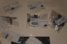
  • Change the resistors to Mils
  • Upgrade the film cap to Mundorf MKP or Silver/Oil (this one is crazy expensive, so I'm not sure I will pick this one)
  • Upgrade the big 1000uF cap to Mundorf Ecap or Mlytic? Which one should I chose? Same price
  • Changing the inductors. And this is the part where I'm stuck. What gauge should I use? And what wire? I was checking the Jentzen air cores.

Also Bruce W. mentioned in a comment under a the absolute sound Q500 test the Zobel network. I have no idea how to implement this hahaha 🙁

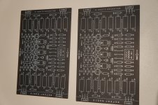
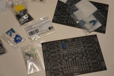
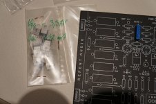
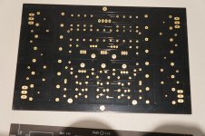
Here is a picture with the two sides of the crossover:
q500 crossover - Album on Imgur

Could anyone help me with this? Is there anyone who already did something similar?

Volt CX220

http://www.voltloudspeakers.co.uk/wp-content/uploads/2014/03/CX220.1.pdf

I have been considering a coax plus second 8 inch bass driver project. I am under the impression that Volt has an excellent pedigree. However, when I look at this response curve, the top end response curve swings around like a logging chain in a water closet. Am I wrong to think that this thing is going to be hellish to deal with?

Cambridge Audio CXC Repair

Recently obtained one of these CD Players and it blows the power supply fuse on start up.
After some experimenting it seems to be problem with either the servo board or the CD mechanism as if the CD draw is out nothing happens. As soon as draw closes and the display indicates "READING" the fuse blows. Disconnecting servo board also stops this happening.
I have requested service manual from Cambridge Audio but at present they are saying pay Richer Sounds for diagnosis and repair.

Anybody out there had a similar problem ?

  • Locked
SBAcoustics SB26CDC-C000-4 ceramic tweeters.

For sale a pair of NEW in their box SBAcoustics SB26CDC-C000-4 ceramic
tweeters.

They are priced to 46€ each and I will sell for 45€ both + PP fees + Shipping
They are NEW.


An externally hosted image should be here but it was not working when we last tested it.

Cambridge Audio CD6 display light gone

Hi,

I was told this was a good place to ask about this!

The light on my Cambridge Audio CD6 display went yesterday, the display still works, if you get up close you can see the readout is working, so I'm guessing its just the light/bulb? But from looking inside I suspect its not the easiest thing to replace. I only have basic technical/soldering skills and would hate to make things worse!

Its not the end of the world and I can live with it but if its a simple job then it would be worth doing.

Any advice appreciated.

Thanks in advance

Steve

How to objectively decide to upgrade caps? TPA3116

Hi everyone,

As many do here, i have a pile of tpa3116 boards that vary in quality (and mods).

I’ve settled on a pair of the dayton branded Sure boards with integrated dsp, etc... sounds good, but I don’t know what their potential is.

Is there an objective way to measure the improvements of the input, bootstrap and output filter caps? I’ve found these boards to be better thought out than the cheap ones i’ve been playing with and don’t want to needlessly cut and slash to install wirewound caps and whatnot if it was 90% as good before.

I have access the standard EE tools: to a nice Tek scope and signal generator, usb sound interface, load resistors, etc....

I was planning to do some THD measurements, but i’m thinking that there should be specific things to look for and likely a specific test that will show how well the LC filtering is working.

Any thoughts?

"Noisy Transformer (Clicking)"

I'm Building an f5 using an Antek AS-4218 transformer (18V, 400VA). I was hooking up the power supply for testing and the transformer makes a clicking noise that sounds like electricity arcing when my ear is a couple feet away. The clicking has a frequency of a few clicks per second. I unhooked everything but the transformer and it still makes the noise with no load on it. I tried moving the amp to a different outlet and the noise is still there. I sent Antek an e-mail a couple days ago but haven't heard back.

Ian Canada Unsealed Unopened UcConditioner 3.3V + 5V Combo [Interest Check]

Hi,

This sale is for shipping domestically within the USA only. I don't want to fill out a customs form.

For now it's just an Interest Check as the UcConditioner 5V is still on it's way from Canada and I should receive the product by end of January 2021.

For my portable project, I was hoping to integrate SuperCaps in the project with these two items. Unfortunately, space it tight for max portability and I am using solid core wires straight to the PCB. This makes it's difficult to conveniently use SuperCaps as I would have to de-solder every time I want to integrate SuperCaps for listening. I cannot just unscrew/screw power cables as originally planned.

The two items have never been opened or unsealed as I am still in the middle of my portable project.

UcConditioner 5V (Regular Price: $59)
UcConditioner 3.3V (Regular Price: $67)

Total Regular Price = $126 + Shipping from Canada

Asking Price $90 + I'll take care of PayPal and USPS Priority Fees within the USA. $90 All-inclusive.

Newbie question - algebra to solve for B+ and Rk?

Bear with me I'm trying to get a handle on basic tube math.

I would be eternally grateful if someone can guide me on the algebra needed to solve this diagram for the unknown B+ and Rk values.

Assuming I know the following static DC values as shown:

250V at the plate
27K Rp
-28.79 grid bias
19.5 ma through the tube

What is the algebra to determine what my B+ and Rk should be to arrive back at these same values? And solve it.

I would assume you have to first solve the B+ then use that to solve the Rk?

Why am I doing this? My load line tool is able to let me try many different plate resistors, plate voltages and currents by just dragging a dot around, easy-peasy. In doing so it gives immediate read out of the NegV on the grid, distortion, Vout, Pout etc. But it doesnt give me a direct reading of what B+ or Rk I'd need to actually build something at that operating point.

So I need to learn how to back into those two values (B+ and Rk) given these four known values, and hoping for some algebra help.

SolveForBAndRk.jpg

Peerless TC9 corner array build (low brow)

I thought I'd start a little build thread on a pair of corner arrays I'm going to build using the Peerless TC9FD18-08's.

By low brow, I mean to describe the lack of sophistication of this build.

That I am not a measurement and graph guru like most of the other line array builders appear to be on this forum.
Also the degree of craftsmanship and quality (both in labor and material) of most of the array builds Ive seen is a much higher level than I can achieve (or care to invest the time in).

Its more of an experiment, like some folks using foam-board, but ill use MDF.
Ive long wanted to try my ear at a full length (room height) array.

The decision to corner build is mostly because I have them.
I use corner horns now, and I love the lack of what I perceive (subjectively) as less early reflections, as compared to tower speakers out in the room.

This build is not a desire to replace my corner horns, its a desire to finally hear a full length array. I certainly do not expect them to play as loud or have near the dynamics. Just a different flavor (hopefully good).

Ive attached a pic of the room (basement) where they'll go, and pics of the 60 little TC9 drivers that just arrived.
The room is 14'.5 wide x 28' long x 8'8" high.

The entire ceiling is un-finished, with ultra touch (cotton) insulation showing, so I may have to install a triangle of sheathing above each array in the ceiling corner to get some of the benefits of a floor to ceiling array, but Ill try it without first.

Attachments

  • IMG_0546.jpg
    IMG_0546.jpg
    87.5 KB · Views: 800
  • IMG_0934.jpg
    IMG_0934.jpg
    92.5 KB · Views: 784
  • IMG_0935.jpg
    IMG_0935.jpg
    75.6 KB · Views: 782

How to determine what is the lowest stable impedance for amplifier?

Hello,
I had modified 100v line amplifier for low impedance load (There is a thread in PA section).

It`s a single channel push pull amp with two MJ11016 transistors and it needs transformer (toroid with no labels) to work.
Rail voltage is 39v dc, only positive and toroid is rated for 100VA.

I had connected 3ohm load to it (pair of 6ohm Pioneer CS-770 speakers) and it plays good. It has a fan that didn`t turn on in 4 hours of listeting to music with volume at half.

146w rms and 292w peak measured.

Now my question is how can I know what is the lowest impedance load that I can connect to it?

I think that if there would be no output transformer, I would need to measure the current and see if transistors can handle it, but what is the case with output transformer? Do I need to measure current before the transformer and see if transistors can handle it and after the transformer and make sure that transformer can handle it?

Thank you

What is inside Thorens MM008 adapting jacks for MC input

I bought a used phono preamp Thorens MM008 like this
Thorens MM008 phono preamplifier - maPlatine.com


Unfortunately the jacks with the appropriate resistive loads (10, 100 and 1 Kohms) for adjusting the MC input are missing.
https://www.maplatine.com/en/4687-thickbox_default/thorens-mm008-phono-preamplifier.jpg


Does someone know what is exactly inside these jacks? Only resistors 10, 100 and 1 Kohms? Or is there more or anything else inside?


I want to make these by myself.


Please let me know. Thanks.

Seas XM001-04 (L26ROY) or XM004-04 (L26RO4Y)

Hi

Does anyone know the difference between these drivers?

Seas XM001-04 (L26ROY) - http://www.seas.no/images/stories/extreme/pdf_datasheet/L26ROY-XM001-04_Datasheet_v2.pdf

Seas XM004-04 (L26RO4Y) - http://www.seas.no/images/stories/design/pdf_datasheet/L26RO4Y-XM004-04_Datasheet.pdf

I'll be looking fit 2 in a single enclosure, ported or transmission line. But wouldn't know which one to buy. Will be used as subwoofer only, normal crossover around 60- 80 Hz.

Any advice would be appreciated. Thanks

Thinking about building a PP 805 amp and have questions

This idea has popped up at the strangest times and won't go away. So I think I should build it. I'm wondering is there is any sound difference between a tube power supply and a SS power supply for B+¿

Is there a good design I should be looking at for a starting point?

It will every large and heavy is I don't go monobloc but I have to weigh that against cost.

ATC Pre-Amplifiers CA2/SCA2 (CA-2/SCA-2) MK-I and MK-II Schematic wanted

A friend tell me, ATC makes one of the best currently available pre-amplifiers.
the model CA2 uses integrated operational amplifiers and the model SCA2 discrete versions similar to such from burson - go to
Supreme Sound Opamp V6 – Burson Audio
and
https://www.diyaudio.com/forums/sol...cial-available-discrete-op-amps-overview.html

Who can upload the schematic diagrams ?
In the attachment images from all models

Attachments

  • ATC-CA2 front.jpg
    ATC-CA2 front.jpg
    216.3 KB · Views: 672
  • ATC-CA2 front-II.jpg
    ATC-CA2 front-II.jpg
    836.9 KB · Views: 827
  • ATC-CA2 open.jpg
    ATC-CA2 open.jpg
    881.9 KB · Views: 727
  • ATC-CA2-MKII_600x600.png
    ATC-CA2-MKII_600x600.png
    150.6 KB · Views: 615
  • atc-ca2-mk-ii-open.jpg
    atc-ca2-mk-ii-open.jpg
    371.1 KB · Views: 553
  • ATC-SCA2.png
    ATC-SCA2.png
    204.2 KB · Views: 545
  • atc-sca2-692638.png
    atc-sca2-692638.png
    467.8 KB · Views: 518
  • atc-sca2-437971.jpg
    atc-sca2-437971.jpg
    199.4 KB · Views: 963
  • atc-SCA2 mainboard.jpg
    atc-SCA2 mainboard.jpg
    134 KB · Views: 580
  • atc-sca2-437972.png
    atc-sca2-437972.png
    537.3 KB · Views: 735

Need advice on Front horn loaded with narrowed expansion

Hi everybody, i am currently working on a Jubilee style project: 2 horn crossed at 500Hz. After extensive research to find the good driver, I went to an Audax PR300M0 (Fs 17Hz, Qts 0.26) and started simulations on Hornresp. You will find below two simulations of front horn loaded, closed chamber.
One has a hyperbolic expansion, the other one is more atypical with a narrowing after first expansion. This intrigues me with its unconventional shape while it offers a much wider and smoother response curve in the low frequencies with a small loss of sensitivity (driver, chamber volume, surface Sd, horn length are identical for the 2 simulations).
I turn to you for advices: should I trust the Hornresp simulation? Should I focus on this narrowed expansion which seems to provide a 1 Pi response from 40Hz to 500Hz with a single 12' driver?
Thank you in advance for your advice and all my apologies for my poor English langage.

Attachments

  • Hyp horn.png
    Hyp horn.png
    605 KB · Views: 106
  • Narrowed horn.png
    Narrowed horn.png
    672.5 KB · Views: 107

WTB: Marantz 2230 or 2230b

Hi,


I'm looking to buy one of these that isn't all beat up etc.
It's for my little 7 year old girls birthday. She loves
music and this will be my gift for her music.


It will be something she'll have and cherish long after
I'm gone.


So if you have one, and aren't using it please consider
selling it to me for my little girl.


I'm a DIYer, with wife and kid and approaching retirement
in a couple of years. I've tried finding a job with my new

skills etc, but they won't hire an older smart guy like me.
They want them young and dumb. Go figure.


Please PM me what you have and what you need for it.


Cheers,

Shiga MKII ultra high grade

Selling my personal Shiga MKII ultra high grade.
It includes:
- two ultra low noise regulators Zeno and Zeno MKII with synchronous rectifier Saligny
- latest cd mechanic modifications with shielding foil
- custom Duelund Ag-Cu for C8
- Z-foil for s/pdif
- lot of polypropylene caps and organic semiconductor caps
- 2 miniregs and 2,5V PIn diode reference
- Dexa Neutron star 2
- bronze cd puck
- IR remote

Sound magnific and will go for 1100euro ex shipping and paypal fee.
What you see in the picture is what you get.

Regards,
Tibi

Attachments

  • image0.jpeg
    image0.jpeg
    123.1 KB · Views: 628

Help with component values please?

I have a plate amp from a subwoofer that has a blown output. The two power transistors (TIP35/36C) have gone short. One of the 0R15 resistors has gone open in the resistor package and then there are two tiny resistors that have released thier magic smoke. Any ideal what the value of these is likely to be?


One measures 42.6 ohms and the other 1K47 but I assume they would have been the same value


I hope I have drawn the circuit right. TIA

Attachments

  • IMG_7066.jpg
    IMG_7066.jpg
    775.4 KB · Views: 163

Pilot 248B Amp with weak channel

I purchased a Pilot 248B Integrated Amp 2 years ago. I fixed some bad components re-tubed it and set the bias according to the manual. The amp worked fine and produced about 30 watts per channel into 8 ohms at clipping.

I gave it to a friend. He contacted me recently because it began distorting badly at power levels above one watt.

I can't find a schematic for the 248B. The attached schematic is for a 264 amp but is similar enough from V3 and V4 thru to the outputs for troubleshooting.

I replaced all the caps in the HV supply and the 100uf cap in the bias supply. The HV supply shows a 10k ohm 2W resistor before V3 and V4. It was bad. In my amp it is actually a 6700 ohm resistor. I replaced it with a 10k 5w resistor.

These changes brought one channel back to 30w output before clipping and the other channel back to ~12w before clipping. I can hear a low level buzz in the bad channel that does not exist in the good channel. Otherwise the sound is good until clipping.

I swapped the 7591s and the 12ax7 amp/pi tubes between the two channels and the problem stayed with the bad channel. I did other tests on the tubes and I think they are all okay.

The 248B has a 100k ohm resistor in series with the input and the grid of each of V3 and V4 audio amplifier stages. The signal before and after the resistor in the V3 channel does not clip up to full power. In the v4 channel it does not clip before the resistor but it shows clipping after the resistor at about 10v peak.

In the V3 channel I replaced the 4700 ohm cathode resistor (it was 5600 ohms on my meter), the 100k ohm plate resistor (120k on the meter), and the coupling cap (it is actually 0.1uf). This did not fix the problem.

Can someone here suggest what I should do next to identify and fix the problem.

Thanks,

Steve

Attachments

How do I adjust amp bias?

I'm thinking of adjusting the bias on my Rotel (class a/b) amp to try to improve the sound. The amp does not heat up even after hours, so it seems like there's enough leeway to increase the bias. So I'd like to know if there's a real simple way to do it, as I don't have an electronics background. I did measure the DC at the speaker outputs with a voltmeter; they read about 58mV for one channel, about 64mV for the other. My question is, can I go by this speaker output measurement to assist me in knowing how far to go with adjusting the amp's bias trim pot, or do I really need to be measuring the legs of an emitter resistor etc? And if I can use the speaker output measurement, which would presumably change as I adjust the bias trim pot, what voltage should I be looking to acheive, or what voltage should I stop at, to avoid blowing my amp (which I believe has no thermal protection for reasons of sound quality)?

btw, I don't have schematics and not interested in acquiring them; wouldn't know how to read them anyway.

Tang, like the old Ultimate

Back almost exactly twenty years ago I made some subwoofers with Ultimate brand subwoofer drivers. They were moderate power (c. 120wrms, decently magneted (c. 40oz), and high compliance (Fs c. 30Hz).

Lately I've been wanting to remake similar subs. However, I was having trouble finding 8" subwoofer drivers like the old Ultimates. The price for the Tang Band ones are about $85 more than the Ultimates were, $115 and $30, respectively. I don't think many items have quadrupled in price like that in 20 years.

DIY shorting ring...

As I needed to repair one of the bass/mid drivers from my recently aquired Philips DSS930, I wondered if anyone tried to create diy shorting rings. I'll try it with silver paint, typically used to repair car rear window heating.
I've tried to cover only the portion of the pole piece above the air gap...
Just curious if there's any experiences already.

Attachments

  • DSS930_AD51603.jpg
    DSS930_AD51603.jpg
    824.2 KB · Views: 870

An inductor to make new e-capacitors seem more vintage?

Hi,

last night I was looking at some new electrolytic capacitors for the power supply of some of my amps and I noticed how old e-caps showed small differencies in impedance between 100 Hz and 10 kHz whilst new ones, due I guess to the egemony of SMPS, have highly improved performances at high frequencies.

So I was thinking how to restore this small difference between low and high frequencies, and first thing that came into my mind are those small cheap inductors seen in battery chargers.

After a short calculation, I saw that in the range of 10-30 uH we can restore that ratio of impedances of the cap. Other point is current. I would consider around 2 Arms to be on the safe side.

While ordering some stuff from mouser, I would add some small cheap inductors (we are talking aroun 20 cents each) to perform some tests.

Has anyone experience in anything similar?

Thanks in advance

Roberto

(AU) A subwoofer for the price of 2 packets of cigs

I have a full HT system but use a Yamaha sound bar (2xTMW) for general daily use. I was looking to build a little woofer to add some lower end and body for when I watch TV movies etc.

Did a design I then looked around for a little plate amp or build an active stage (buffer/filter/phase) to partner a Class D amp. While researching a plate amp I found a completed sub for A$89 delivered from DJ City in Melbourne to Newcastle. The idea was to strip out the amp.

It's a Fenton SHFS08B which is cheap and cheerful and even though there's a lot wrong with the design and build, it works well to add some bottom end to the soundbar. Sure the bass is a bit one note and the gain must be a zillion dB but it saves me building one at a much greater price. How do they sell it so cheap as there is 10% GST plus shipping? I'm amazed how cheap this thing is and it even comes with a removable IEC lead.

The amp looks like Class D and the active stage uses 4558 op amps. The only thing I had to do was add a gasket to the woofer, seal the hole for the speaker wire and countersink the screw holes.

The specs are very optimistic and can be found here:
SHFS08B Active subwoofer 8" black - Speakers - Home HiFi - Tronios.com

Attachments

  • Fenton100305.jpg
    Fenton100305.jpg
    33.4 KB · Views: 172

Modifying Troels Gravesen's cabinet design

As some of you might have gathered, I'm in the process of building Troels Gravesen's new The-Loudspeaker-III.

I'm currently extensively modeling the speakers in Fusion 360 (a CAD software) to try a few different designs (different colors, veneers, speaker stands) to tailor them to my taste.

On his website, Troels states the following: "Due to the NSD1095/XT1086 horn delivering the same frequency response regardless of front panel design, there is a great deal of freedom in this construction. Only key elements are the horn tilt and the displacement of the midrange driver relative to the horn and keeping the midrange front panel some 230 mm height with driver in middle. So stick to the upper front panel design! Almost anything else you can do to your liking and it will perform as intended."

I have trouble understanding what this 'great deal of freedom' is.
I get that I shouldn't mess with the horn tilt, nor the midrange driver being on top of the horn, and the midrange front panel being 2300mm.

* Can I flush mount the drivers to make it look a little cleaner?
* As the midrange has its own cabinet, can I detach it from the rest of the speakers and have it resting on top? This would allow me to build two different cabinets and increase the possibility to fine tune the speakers visually.

I'd rather ask here than keep bothering Troels with stupid questions every few days.

Upgrading mids - Eighteensound 12ND710?

Hey all, as I finished building more subwoofers last year, I am looking to upgrade my mids during 2021. I think im going to construct another couple of simple relfex-boxes, I mostly play indoors in smaller venues so I do not think horns would make much sense for me, it's not a "festival main stage"-soundsystem. The dancefloor always ends up being right in front of the stack.

I am going to have just two mids, so I want to get a couple of great quality ones.

Im upgrading from Fane Sovereign 12-300 (~80€ each), so I do wish to get a noticeable difference in sound quality.

Do anyone here have experience with these specific drivers? The tuning would be from 160hz to wherever it sounds best to cross with my BMS 4554", so probably between 1600-1800hz.


Eighteen Sound - Professional loudspeakers


"The 12ND710 has been specifically designed for use either as a midbass driver in compact 2-way reflex enclosures or as a direct radiating or horn loaded, dedicated midrange drive"

I am also open to any other suggestions for some great mid-drivers to couple with my Fane Colossus 18XB & BMS 4554, between the ~250-350€/each range.


WEZ9JFj.jpg


An externally hosted image should be here but it was not working when we last tested it.

Rotary encoder / volume control

This question pertains to the rotary encoder that is used as a volume control on the miniDSP 4x10 HD.

So far, I have used the outputs from the 4x10 to feed the multichannel inputs on an AVR. The AVR has a decent volume control which has provided that function for me.

I will soon replace the AVR with a multichannel power amplifier and will thus lose that volume control. The obvious thing to do is to use the volume control on the 4x10.

Here's my question: is it possible for the miniDSP's rotary encoder volume control to fail in such a way that unattenuated signals are passed to the power amp? I have little faith in the reliability of these multifunctional gadgets, and such a failure would obviously be disastrous for my speaker drivers.

If there is any possibility of this whatsoever, I will fit a multichannel volume control in the inputs to the power amp.

All opinions are invited, although I would like them to be endorsed by a miniDSP representative.

Thanks!

JBL LSR4328

I have JBL LSR4328 Studio Monitors. One of the monitors will not turn on. The JBL emblem light is on but the speaker will not power up. Has anyone encountered this problem. These monitors only have about 50 hours of usage if that. I bought them new and were barely used. Also, if anyone has a schematic with test points, that would probably be helpful.

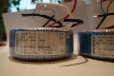
FS: Transcendar Power Transformer

Brand new, never used. Originally purchased for the RH84 amp build (second power supply schematic)
RH Amplifiers: RH84 amplifier - revision 2

120V primary

850 VCT @ 120mA
6.3V @2.5 A (no center tap)
5V @ 3A (no center tap)

$100 shipped UPS to lower 48 US.

Paypal

Attachments

  • IMG_20210215_190229635.jpg
    IMG_20210215_190229635.jpg
    983.8 KB · Views: 144
  • IMG_20210215_190225329.jpg
    IMG_20210215_190225329.jpg
    1,001.9 KB · Views: 149
  • IMG_20210215_190218260.jpg
    IMG_20210215_190218260.jpg
    944.3 KB · Views: 138

Simple SE Cathode Bias Question

New build for me. I am not an EE, just a DIY enthusiast. I will be using an Allied 6K7VG power transformer and only SS for power supply. I understand that B+ voltage will be a bit higher this way. Using EL34 as power tubes, will a 560 ohm cathode resistor still be OK or would it be better to increase the resistance of Rk? If yes, what value would you recommend?


Thanks for you help.

Ground loop hum between preamp and amp. Help!

McIntosh MA7900 (via unbalanced RCA outs...no balanced so unbalanced my only choice) to MC275 tube amp.

If things are hooked up with my 89 dB. speakers...can only hear it if in a DEAD quiet room and my ear is right up against the tweeter, there is the faintest noise I can barely hear. However, on my sensitive, no-crossover, full-range driver speakers (which are brutally revealing), I get some annoying hum. The hum is the 60 cycle ground hum (as validated by some YouTube clips).

--If the speakers are connected to the SS amp (MA7900)...nothing
--If the speakers are connected to the MC275 and I switch off the MA7900, goes away 100%
--It is not volume, input sensitive (same level from speakers no matter what, even if I mute the MA7900 or shut off the output to the amp).
--If I power off and/or unplug the MA7900, the hum goes away, and instantly comes back when I switch it in (even during its ~10 second warm up where it is not outputting any signal)
--Both power cables are connected to the same bank on a Panamax 5300 power conditioner
--If I unplug the RCA to one channel, the hum goes away 100% and remains on the other channel
--I tried plugging both directly into the wall outlet and it didn't change (meaning there was nothing else within 10' plugged in to power, including anything like phone, coax, etc.)

If it were not for the sensitive speakers, I would never have noticed. Even with the sensitive speakers, it is just *barely* noticeable from listening distance, but feels like it should not be there at all.

However, I now have that 'itch' to try and fix it and curious where to start. Based on the above, can you help me isolate where to start, what to try? If the answer is get a real preamp with balanced connections...well that would work!

Thanks!!!

Another F5 with different FETs

Six years ago I built my F5 with extremely well matched Toshiba 2sk170BL and 2sj74BL (P-channel with Idss about 1.1mA higher than N-channel to create perfect complementary pair - P-channel scaled down to match the curves). IRFP240 and IRFP9240 Vgs matched at 1.3A by Alex (he always matches MOSFETs perfectly!).

I am very happy with it, it sounds great with most speakers.

Recently I found 80pcs of used 2SJ554 and 2SK2955 that I purchased years ago and I matched 2 pairs. Photos attached. I noticed that they have a much higher gain than Vishay MOSFETs, also lower Vgs, so I thought it might be a good idea to create another F5 with better complementary pair, NEC 2SK163M and 2SJ44M with Idss at about 11mA, they have lower gain than Toshiba JFETs. I have done a simulation (ASC attached), but don't have models for HITACHI MOSFETs so I used TOSHIBA which is quite close (thanks to Patrick EUVL). Changed input JFETs resistors to 2.2k as they have lower input capacitance than Toshiba JFETs. Lowered MOSFET gate resistors as HITACHI/RENESAS has higher Cgs capacitance. Also, MOSFETs source resistors reduced to 0R1. Biased at 1.36A. Of course, I would use NTC thermistors that are not on the schematics. The gain is 15.4dB. At 1W the 2nd harmonics at -84.5dBFS.


What do you think about it? Any suggestions, do you think it's worth trying?

Attachments

  • F5-renesas.asc
    F5-renesas.asc
    5.1 KB · Views: 59
  • FFT-at-1W.png
    FFT-at-1W.png
    4.2 KB · Views: 295
  • mosfet-comparison.png
    mosfet-comparison.png
    18.5 KB · Views: 304
  • two-pairs.png
    two-pairs.png
    15.7 KB · Views: 300
  • schematics.png
    schematics.png
    10.2 KB · Views: 300
  • ripson-f5-front-panel.jpg
    ripson-f5-front-panel.jpg
    77.4 KB · Views: 308
  • ripson-f5-backpanel.jpg
    ripson-f5-backpanel.jpg
    129.3 KB · Views: 134

85/90 volt CLC supplies (Hafler 500/600)

My next project was in building an over the top (bordering silly) big P/S to run a Hafler 500/600 modeled amp and eventually use the Exicon T0-264 dual die MOSFETS or possibly 2 pairs per chassis, of Hypex UCD 400/700 or ICE500/1000a power modules to build mono blocks for bi-amping my Maggies. A whole other post and topic [later this year]

I chose to layout the amps differently due to using a larger 1000va toroid and the huge United Chemi Con electrolytics. This supply will drive the "Hafler 500 or 600" with great reserve and will (eventually) easily have dual amplifier modules per chassis. At this point I still consider these proof of concept builds... as I am experimenting with parts and wiring layout. I have listened to the 500 heatsink with Musical Concepts PA7 driver boards for about 3 weeks and am very happy with results, it is amazing. *I chose these large 39,000 mfd caps, in that *IF* I did not like the result, I could repurpose them in a "stock chassis" of a 500 or 600 amp...

In the meantime, while I re-built the chassis pan of my XL600, using Cardas RCAs and 5 way binding posts, along with heavier gauge wiring, cleaned up the AC wiring layout and installed an IEC jack. I stripped the amp down exactly like the 500 to keep everything the same... for easy comparison. Right now the XL600 is powered by the Franken'Amp CLC supplies... I have only taken a few pictures... too busy listening. This 3 piece Franken' amp is a monster, frankly I am nearly surprised I have not popped fuses in the Maggies, not by abuse or clipping... simply putting humongous amounts of power into them. I never heard any Maggies or my Maggies play like this... I doubt the I would ever need a subwoofer... they do ~ big ~ tight ~ bass. This amp configuration exerts incredible bass control over the panels...

The vertical layout created room for the audio circuit (in the back 1/3 of the amps) and I was feeling driven to isolate the magnetics of the toroid and inductors from the audio circuitry... I pondered the parts in various layouts for over a month and finally resolved all of my goals with this layout. I wanted to keep the wiring paths short, symmetrical and tidy [rats nests make me crazy] not judging anyone else's work, I am my own worst critic.

This power supply driving "Hafler 500 and 600" has ridiculous clarity, sense of finesse and effortless ease. The Macro and micro dynamics are unparalleled, compared to any amp that I have built in 40 years...

My reference for sound has been the Futterman OTL4 sitting in the middle of the frame... I have only powered it up ~once~ the past 2 months of being blown away by the CLC designs. I wish my OTL tube amps could play like these... there are ways that I prefer the solid state (yes, I said that).

Attachments

  • CLC 550 5187 sm.jpeg
    CLC 550 5187 sm.jpeg
    643.4 KB · Views: 155
  • CLC 550 5191 sm.jpeg
    CLC 550 5191 sm.jpeg
    450.3 KB · Views: 158
  • CLC 550 5192 sm.jpeg
    CLC 550 5192 sm.jpeg
    500.6 KB · Views: 145
  • confined AC power 5189 sm.jpeg
    confined AC power 5189 sm.jpeg
    451.9 KB · Views: 139
  • CLC 600 5246 sm.jpeg
    CLC 600 5246 sm.jpeg
    635.2 KB · Views: 147
  • CLC 600 5247sm.jpeg
    CLC 600 5247sm.jpeg
    486.8 KB · Views: 110

Building the Apex A40

I have used the forum in recent months to help with repairing a few amps for friends and so am listening to proper hifi again (the repairs were successful 🙂) rather than the Sonos I'm used to so this led me to think about buying an amp but while thinking about that I've decided to build one instead.


Although I'm used to working with electronics it has mainly been digital so it's great to see so many good designs on here as I really would not know where to start designing one. I would however say that the organisation is terrible 😀 so investigating different options has not been so easy.

I seem to have settled on the Apex A40, it looks like a great amp to build. I would like to ask some questions before I start and just wondered about how to do that. Many people seem to post on the 100w-ultimate-fidelity-amplifier about various different Apex designed amps which to me a little confusing.... or should I start my own thread?


Well I'll ask a couple of questions now anyway:

Is there some system to find the latest info on this design? I see that alex mm posted some great looking PCB's in January 2015 but do I need to read every post since then to find if there were errors or improvements?

Everything I see on here seems to be through hole construction, is there a reason for that? I would like to change at least some of the smaller components to surface mount if only to feel that I've had some input in the design process.


Thanks Simon

Going rate for plans...compared to the dear LX mini

I may get flamed for my first post being on this topic, but let me state up front that I absolutely have no issues with paying for intellectual property. As a related example, I just sent off for a custom t-shirt today (personal use) and paid royalties ($10 each) for a couple of clip art items that fit the bill. And yes, to me $10/single use seems high for clip art....

I’m keen on trying the LX Mini +2 project but have hesitated on the $160 plans. I realize I’ll come across as a cheapskate, so help me. Is this high, cheap or middle-of-the-road?!?

Thanks,
Z

I’m 51, and no I’m not yelling at clouds or to get off my lawn. 🙂

ST-120 bias question

Hi everybody!
I have this bias adjustement issue on V3, I can turn the potentiometer all the way and still got only a 0.4V reading.
So I suspect the dedicated potentiometer to be faulty, am I right?
Changing tube placement do not change anything!

It’s a tight fit here, I did a custom casing so need a Mouser part number.

This one?

3386P-1-503LF Bourns | Mouser Canada

thanks’!!!
Denis

Screen grid, zener circuit: any concern?

Hello, I've build this (found somewhere from internet) and it sounds good.

No audio problem, nor THD% change. It seems less booming bass and more available dynamic.

Now screen should work just at little bit lower voltage than the plate. Safe but nearly the max allowed (i.e at plate voltage). But I didn't measure voltages yet.

Any concern about this zener circuitry (instead connecting it, as usual, to the lower voltage power supply of the previous stage via a kohm resistor) ?

Thanks

Attachments

  • zener.jpg
    zener.jpg
    16.6 KB · Views: 996

Back to back transformers for isolation plus filtering

I have assembled a pair of approximately 900va transformers to function as a line isolation transformer. These are placed inside a steel cabinet and are fused at 8A, using a circuit breaker, and definitely improved the noise floor of the digital player/DAC, and a/b amplifier setup.

What I am now wondering, is if there would be any advantages to having the differential mode X capacitors between the two secondaries, as opposed to have them after the dual transformer configuration, as they now are?

Nakamichi BX-100 cassette door stops motor

I picked this deck up from a friend who said he plugged it in and it worked for a short while then stopped. Hadn't used it for years. I replaced all belts and capstan tire, but still would not operate. After a good while of looking around, I realized that unit will work, but only if the cassette door is pushed inward just a very small amount and seated. Let go and it stops again. The push is only a 16th of an inch or so. Is there an adjustment for this door so that it locks fully seated?

Thx
Mark

E-MU 0404 USB mic inputs dead

Hi!

Have a problem with my trusty E-MU 0404 USB interface. Recently did a software update to 1.40 BETA (Creative site) which froze the unit and killed both the mic inputs somehow. Now I don't get any sound wave from the mic, just static noise which sends the levels clipping. So no sound and a tap on the mic will be enough to make loud cracks, even if mic input levels from unit are at minimum. Also the mic channel volume leds show this, they go completely haywire.

I uninstalled software + drivers, reinstalled the previous version and updated firmware. Got perfectly normal clear sound from mic inputs for 2 minutes, after that the sound died again.

The weird thing is that all the time system sound works perfectly normal.

Have tried different mics and cables, with phantom and without. Changed E-MU power supply to another one. Opened the unit to visually inspect for bad caps (none showing). Swapped sample rates around (the only working one for me has always been 48kHz).

I'm really at my wits end here. I hope someone can help to bring this good old kit back to life. I thought it could be a hardware problem, but the problems came straight after the software update AND both mic inputs died at the same time. Also confusing is that I got it working briefly after downgrading software. 😕😕

Thanks in advance!

PSU Designer II Warning Message

When using PSUDII I often get the warning message:
"A current sink has pulled the voltage below zero for more than 5 cycles, at time ..."

I understand that tubes are not a constant current sink on startup, but what when they are already hot and you turn them off and on again in a quick succession ( hot start), would this pull the voltage below zero and what effect would this have?

There must be a reason why the designer of PSUDII added the warning.

When entering known working designs of amps, as in the attachment, I do get the message which is odd to me.

Attachments

  • PSUD warning.JPG
    PSUD warning.JPG
    81.9 KB · Views: 208

HP 339A - I need help for trouble shooting

Hi all,

I have problems with the calibration of my HP 339A Distortion Analyzer. According to the manual at the ADJUSTMENTS SECTION V 5-10, I zeroed the meter without power and the result is okay (Pic 1). But when I switched on the 339A there is a deviation (Pic 2).
The next problem is that I can't adjust the 3 Vrms according to 5-12. The maximum voltage I can adjust is 2.93 Volts (Pic 3).
My power source unfortunately is not an AC calibrator but a HP 3325A with a quite clean 1000 Hz signal at 3.0005 Vrms.

Does anyone has an idea where to start the trouble shooting?

Many thanks in advance for your help
Michael

Attachments

  • Meter without power.png
    Meter without power.png
    238.6 KB · Views: 112
  • Meter switched on device.png
    Meter switched on device.png
    196.7 KB · Views: 106
  • Adjust 3 Vrms.png
    Adjust 3 Vrms.png
    249.6 KB · Views: 110

Need help with amp

After 4 years I decided to use again my Copland CTA-401.
It started working good, but after an hour the Main fuse(3,15A) burnt. I replaced it, but it burnt again, immediately.
I decided to control, looking at all parts of the amplifier.
This is the schematic: http://www.audiokit.it/ITAENG/UpElettr/COPLCTA401/Sch401-1-1.jpg

R34 seems to be "cooked". the other 3 resistances of same purpose(R33, R133, R134, in the other 3 tubes) have the red band visible. The red band of R34 became "darky", and also silver and gold bands are darker. I decide to measure: R34 indicates 819 ohm. the other 3(R33, R133 and R134) measure 812ohm.

What happened? Do you think I can simply change that resistance and try again, or is better to control every part? Maybe there are problems with the tube or with the output transformer? 😱

Thanks to everyone can help me!

PIC based stand alone soft start

I know, yet one more soft start 🙂

But here it is, I'm sharing what I have, which may be of interest to some users.

It's only the soft start function, for one toroid only, and it's activated by a push button with a led to show status.

Nothing more beyond that. No dc blocker, no snubbers on the mains, except the one on the triac, no ground lifter or anything else of that nature.

But also no electromechanical relay, no power dissipating stuff like power resistors, no MOVs, nothing bulky.

Just an 8 pins PIC to handle it all, by phase control, like a plain old dimmer.

The unit is in standby when power is first applied, waiting for the push button to be hit. When the button is hit, the start up sequence starts, the led blinks during the whole process, while the push button is ignored.

Once the full sequence is done, the led and toroid are fully turned on and the push button is polled again, with a small delay, waiting for the next push to shut the unit down and go back to stand by. The led is turned off as well as the toroid at that point and so the status is back to the same as when power was first applied.

The pcb is 55x70mm. The PIC can be reprogrammed on board via the ICSP header and a pickit or whatever is used to do pic programming.

I will post more stuff in a while. The gerbers, pic asm source code..

I have already verified the software using a breadboarded version of the circuit on a 200VA toroid, and it worked just fine. I didn't have a bigger toroid handy, so I don't know how it will behave on that, but the software is easily adjustable in case of need for a hard to handle load.

I have pcbs coming to me, so I'll be testing the whole thing built for real in a few days.

Maybe this might be of help to some users, so I'm sharing it.

The start up sequence is smooth, starting with pulsing the triac gate (~250us) at ~9us from zero-crossing, for several cycles, then the delay decreases by ~500us at each step in the sequence, all the way down to zero delay when the sequence is all done and the triac is then fully turned on permanently (well, at least until we tell it to shut down, or power is lost).

The zero-crossing is sensed via optocoupler, as well as the triac triggered via optotriac.

I used a 5V power module instead of a transformer based PSU for the pic power, so fewer parts and smaller footprint overall, plus it turns out a bit cheaper as well, not to mention simpler to assemble.

I priced all the parts from mouser and compiled a excel based BOM, which should make it easier for anyone to make. It's fairly cheap to make, with less than 15euros worth in parts, plus the pcb.

Attachments

JVC PC-X1000

Just bought this boombox the Other day

5CyFsW9.jpeg


Its from the year 1990 i think. The boombox has a power out put of 70w 17wx2 and 36w to the sub. However tape deck A doesnt fast forward or rewind and the cd changer doesnt recognise that there are discs in the cartridge any idea what it might be? Ive tried cleaning and tweaking the laser and have changed the spin motor out. When you load a disc and hit play the disc doesnt even try to spin and it has me puzzled. Any help would be appreciated. Also does anybody know if there are any boomboxes that are more powerful just out of curiosity. Ive heard on other forums that were are old yamaha boomboxes that could destroy the 1000 but when i looked them up i couldnt find any with as high outputs. Ps half of the pictures didnt upload but im too lazy to go back to try to upload them again

Wiring for fullrange drivers?

Hello everyone. I am posting a topic that has been long debated over and over again. I am posting to get some ( hopefully down the Earth answers ) about some wire brands I am looking at using? Or share what you have used and how it has worked in your system? Here are a few companies I am looking to buy 12 gauge wire from?

1. Mono price wires? They have mixed reviews about the grade of copper they use?

2. Gotham Cable. It's good cable and it works. Ask Mr. Pass labs.

3. Canare Cable. It's good Cable and some think their focus on twisted shielding hurts the sound?

4.Sommer Cables. Not much about them but their catalog they send me is huge.

5. Nvx and knukonceptz they look amazing for the 12 guage wires? They are priced well but, are they worth it?

6. Jsc or Carol or sewell wires? Not much about them or anyone using them?

These are the speaker wire companies am looking at using for my speaker system. Tell me what you think? Thanks Jeff

AMC CVT3030

Help with B+ supply mod (gyrator?)

Dear community,

A few years ago, I got my AMC CVT3030 amp modified. One of the modifications was along the B+ supply to the tubes (gyrator?). While the acoustic result was very good, the execution of the mod, as you can see in the picture, was outrageously sloppy if not dangerous, to say the least.

Recently something got wrong with it while I was re-soldering a few shaky spots. Now I do not know how to fix this masterpiece which contains also some random components just hanging loose (!!!).

So I am thinking of reviewing and rebuilding it, possibly with your help.

I am attaching a schematic I drew just by inspecting the piece of junk. As you can see in a couple of spots I do not even know if there is a connection or not. In the schematic I also included the large capacitors at the input (from the rectifier bridge) and output (rated 450V and 400V respectively).

Since this circuit is intended to provide a clean supply to the tubes I could also explore the alternative, possibly easier to implement, to eliminate the old mod and add the following Tentlabs module> Electronic Choke

What do you think? Would it be worth to try rework the old mod into a new one or just go with the Tentlabs module?

Thanks very much
Fabrizio

Attachments

  • schematic.png
    schematic.png
    12.6 KB · Views: 708
  • IMG_3173.jpg
    IMG_3173.jpg
    592.4 KB · Views: 671

Laser Diode always on

Hello Everyone,

I have bought a used CD-Player from Ebay and Onkyo C-733 to match it with my Onkyo R-N855. The CDP sounds gound enough for me and purposes.
It arrived in mint conditios. It also sounds much clearer than my other CDP.

Anyway what I wanted to discuss is actually following:
When opening, taking the lid off, the CD player for inspection I have noticed that the laser diode will never switch off when the device is on. Is this normal with this machine?

All my other CDPs did switch the laser diode off when no disc was recognised.

Any suggestions?


-Best

Dutchvan
JBL recone

Hello to all on this beautiful Valentines day. I hope you all are enjoying the company of another! However, lol... I have a question to interrupt your festivities. I'm sure this question has been asked... Owning a pr. of JBL 2205J woofers, I wanted to know of anybody taking any 15" frame and having it re-coned to match a different model's spec.? Turning a 2205j into a 2226H for instance...? Is this possible and to what success?

kingfisher

Lesser of two evils for TPA3116 input caps : 0805 ceramic or foil with wires

I’ve got this dayton dspb-250 amp and the sound is... worse than the other 3116 amps in my pile here.
I’m trying to do some upgrades, the input caps are 0805, but i’d like something better (and smaller capacitance). There’s no way to mount the smd version of the wima mks-2 caps i was looking at without putting them on a small board nearby with some flying leads. My instinct is that this is probably still better than the stock ceramics (of unknown value)

It doesn’t look like any film caps are small enough to fit 0805 (i could maybe squeeze 1206), even at the small values of .47-.22uF that i’m looking for.

Does anyone have experience with this problem? Are there better caps in the 0805 size or should i just use the through hole caps with wires...

Attachments

  • 6DCC906B-3CBF-4D00-AF07-230695542B5B.jpg
    6DCC906B-3CBF-4D00-AF07-230695542B5B.jpg
    930.6 KB · Views: 126

Headphone Advice, HIFIMAN HE400se vs SHP9500 vs SHP9600

I am looking to buy new headphones and wanted your opinion on which headphones to buy. In my country, I can buy the He400 Se at 128 USD, SHP9600 at 135 USD and SHP9500 at 100 USD. My preference for sound is:

- Good soundstage and imaging
- Neutral but has a little bit of punch
- Nice Vocal body
- Non sibilant (zero listening fatigue)

So, which of the headphones will be suitable for me? Thanks!

Advice on drivers for Sub-woofer

I need low end to compliment a pair of speakers I made.

How do I go about looking at Thiele-Small parameters to determine the right choice. I'm interested in a bass range from 30-70 hz approximately. I'll be driving it with this amp.

Dayton Audio DTA-2.1BT2 100W 2.1 Class D Bluetooth Amplifier with Sub Frequency Adjustment

I'd like the speaker driver/box to be as small as possible.

Could someone please advise on how to go about just using Thiele-Small parameters.

Any advise is welcome.

Regards,
d.

In the meantime, I've just come across a driver (that is very large) used for bass guitar and on sale. Even though this goes against the size constraint, could it be used i.e. Celestion BL15-300X. Here are the parameters.

Celestion BL15-300X (8) - 15 inch Bass Guitar Speaker

General Specifications

Nominal diameter 381mm/15in
Power rating 300Wrms
Nominal impedance 8Ω
Sensitivity 96dB
Magnet type Ferrite
Voice coil diameter 63.5mm/2.5in
Coil material Copper
Cone material Kevlar loaded paper
Former material Polyimide
Surround material Cloth-sealed
Frequency range 42-3500Hz
Xmax 4.25mm/0.16in
Gap depth 8mm/0.31in
Voice coil winding width 16.5mm/0.64in

Small Signal Parameters

D=0.33m/12.99in
Fs=48.1Hz
Mair=14.15g/0.499oz
Qms=2.989
Qes=1.004
Mmd=68.24g/2.41oz
Qts=0.751
Re=3.15Ω
Vas=137.69lt/4.86ft3
BI=8.83Tm
Cms=0.133mm/N
Rms=8.327kg/s
Le (at 1kHz)0.47mH
Projects by fanatics, for fanatics
Get answers and advice for everyone wanting to learn the art of audio.
Join the Community
507,782
Members
7,888,262
Messages

Filter

Forum Statistics

Threads
406,230
Messages
7,888,262
Members
507,782
Latest member
stanyoung