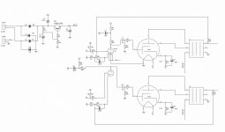
Hi, on the bay I've found a pcb kit with components (no tubes nor chassis, nor transformers, just pcb and pcb mounted components) with the attached schematic.
I'm thinking about buying it, because it's just around 20 euros, and I would like to mount more powerful octals (anything bigger than KT88 that doesn't costs like KT120&KT150?), and apply some mods, like shunt feedback and fixed bias.
What do you guys think? Is it something that can sound good?
Thank you in advance.
Roberto
Attachments
Thanks audiowize,
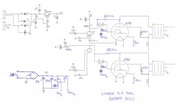
posts like yours are exactly the reason why I'm asking here instead of just buying: I like to have more points of view. I have to say that with EL34 also a 12AX7 seems to work pretty good: the gain lost with shunt is almost gained back avoiding gnfb and ultralinear taps.
posts like yours are exactly the reason why I'm asking here instead of just buying: I like to have more points of view. I have to say that with EL34 also a 12AX7 seems to work pretty good: the gain lost with shunt is almost gained back avoiding gnfb and ultralinear taps.
Whatever happened to Point to Point wiring?
You can easily modify such an amplifier every month.
Get some terminal strips, etc.
How many mods can you do to a PCB, before some of the Pads lift off?
Purchase a power transformer for two EL34 and two 12AX7 tubes, and then expect to power a pair of KT88 tubes? Perhaps with good pre-planning.
But then expect to run a pair of KT120 or KT150?
And if the B+ uses a regulator transistor, check to make sure that it will work at the higher current.
What is the optimum output transformer for EL34 and KT88?
(not even close for KT120 or KT150).
After you build a stereo single ended EL34 amp, you can make it into a push pull EL34 mono-block and duplicate it.
Point to Point gives a lot of flexibility.
If you want to do simple, then use an LM334 current sink, a 12AY7 cathode coupled phase inverter, and 7591, EL34 or KT77 in Ultra Linear.
Nothing fancy.
EL34 and KT77 are plug and play (same specifications, just Pentode versus Beam Power). Pin-out, tie pin 1 to pin 8 (required for EL34, OK for KT77)
7591 does not fit in the EL34/KT77 spot (different specs and different pin-out). But the above topology, and 7591 is one of my latest amplifiers.
It is not powerful, just simple, elegant, and good sounding. See my post in this Tubes / Valves part of this forum:
"A Simple Low Power 7591 Push Pull Amplifier"
I also built the same topology using an LM334, 12AY7, and two KT77 tubes.
These may not work for you, but sometime after you try single ended, you may want to try push pull.
I designed and built a single ended KT66 amp that I have been using in Triode Wired mode and Ultra Linear mode.
Last edited:
You should take a look at the following video which shows you how to build a KT88 SE amp in great detail. It will take a while to go through all the videos but it is worth the time.
KT88 - Single Ended Tube Amplifier Build 2018 - Part 1 - YouTube
ray
KT88 - Single Ended Tube Amplifier Build 2018 - Part 1 - YouTube
ray
Thank you for the suggestion, indeed it's what was happening on the pcbs that I used as bench test for my tube guitar amps. I ended up using fleas, but I agree it's not optimal.Whatever happened to Point to Point wiring?
You can easily modify such an amplifier every month.
Get some terminal strips, etc.
How many mods can you do to a PCB, before some of the Pads lift off?
I will read that carefully and revert to you in case of need. I'm not used to 7591s.7591 does not fit in the EL34/KT77 spot (different specs and different pin-out). But the above topology, and 7591 is one of my latest amplifiers.
It is not powerful, just simple, elegant, and good sounding. See my post in this Tubes / Valves part of this forum:
"A Simple Low Power 7591 Push Pull Amplifier"
During my summer vacation I'll build most of a Baby Huey EL84, the idea came exactly as you said: compare both options. I know sonic the difference in guitar amps, but I would like to hear it in hi-fi too.These may not work for you, but sometime after you try single ended, you may want to try push pull.
I think this can be helpful to adapt the sound to the sound pressure you hear the music in that particular day or to a different kind of music: triode for low power times, UL when you need more power and want to keep the distortion low. Can it be?I designed and built a single ended KT66 amp that I have been using in Triode Wired mode and Ultra Linear mode.
Thanks Ray, I will for sure! I'm doing some simulations as well.You should take a look at the following video
Thank you zlab, I've never seen that name until now, I will search for sure!Take a look of history post of boyuu a10, you will get a lot of idea.
Hi, on the bay I've found a pcb kit with components (no tubes nor chassis, nor transformers, just pcb and pcb mounted components) with the attached schematic.
I'm thinking about buying it, because it's just around 20 euros, and I would like to mount more powerful octals (anything bigger than KT88 that doesn't costs like KT120&KT150?), and apply some mods, like shunt feedback and fixed bias.
What do you guys think? Is it something that can sound good?
Thank you in advance.
Roberto
You could get a Tubelab SSE board.
Both of those mods have been made and experimented with in a completely non destructive manner to the PCB.
More info on these boards and things that have been done with them are in the Tubelab sub forum.
Sorry for questions that can seem pedantic to some, or just really obvious.
While reading this: PassDiy
It came to my mind how, while simulating possible primary impedances, I noticed how changing it there was a dominance of 2nd harmonic, then balance between 2nd and 3rd, then prevalently 3rd. All other harmonics are at least one order of magnitude lower.
What do you usually do on this topic when designing a SE amp?
Considering SA3sUMMER suggestion, could this be something to start with?
2019 ICAIRN AUDIO Offerta Speciale Home Audio Amplificatore a Valvole di Montaggio FAI DA TE Kit 6N1 + 6P1 Amplificatore di Potenza FAI DA TE 4W + 4W AC110V/220 V Opzione|Amplificatore| - AliExpress
Thanks, I will give it a look!You could get a Tubelab SSE board.
If you're designing a single ended pentode amp, often it's a bit of a struggle to get distortion down and damping factor up enough to make the amp usable, so in the end you take what you can get!
I measured an amp recently built by a well known guy who sells on eBay and it used the output transformers in the amp you just linked to. They made a little less than 1/4 of a watt at 35Hz.
I measured an amp recently built by a well known guy who sells on eBay and it used the output transformers in the amp you just linked to. They made a little less than 1/4 of a watt at 35Hz.
zintolo,
One problem with most of those kits is that they use Magnetic Steel Chassis.
Just one source of hum that can not be completely eliminated.
Single ended transformers (with non-interleaved Es and Is, and an Air Gap) are sensitive.
Push pull transformers (with interleaved Es and Is, and no Air Gap) are less sensitive to that.
And Steel chassis are very hard to drill and cut, if later you want to make a modification.
But, if it gets you started with your first build, you will end up with something to listen to.
Warning . . . you will get the tube bug really bad, and you will eventually build at least one more tube amp.
Last edited:
I've found this very interesting post by Tubelab: Single Ended EL34 AmpWhat do you usually do on this topic when designing a SE amp?
It would be great to understand how to modify the contruction of the OPTs to make coincidence with chosen output tube and best OPT current.
Thanks, shunt feedback, higher Ra and fixed bias (so lower Rk) would be a tentative to increase damping factor (and linearity), indeed.If you're designing a single ended pentode amp, often it's a bit of a struggle to get distortion down and damping factor up enough to make the amp usable, so in the end you take what you can get!
I measured an amp recently built by a well known guy who sells on eBay and it used the output transformers in the amp you just linked to. They made a little less than 1/4 of a watt at 35Hz.
 message receipt, thanks!
So another vote not to buy those kits... thanks!zintolo,
One problem with most of those kits is that they use Magnetic Steel Chassis.
Just one source of hum that can not be completely eliminated.
For my guitar amps I used 316L stainless steel, that is austenitic and IIRC due to Nickel is not magnetic. Laser cut and bent, because it's a nightmare to drill.
Warning . . . you will get the tube bug really bad, and you will eventually build at least one more tube amp.
I know I will! After the first tube guitar amp I've built something like... a dozen.
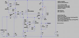
A friend of mine gifted me that module, and while I'm buying new output transformers for the PP amp, I would like to order transformers for this amp too.
I came out with the attached schematic:

that gives 11 Wrms with the following data:
this at 10 Wrms:
and this at almost 8 Wrms:
Does anyone see any way to simplify it or improve it?
I'll sketch it also in PSE with two EL34 in parallel per channel.
Thank you in advance,
Roberto
I came out with the attached schematic:
that gives 11 Wrms with the following data:
Code:
Harmonic	Frequency	 Fourier 	Normalized	 Phase  	Normalized
 Number 	  [Hz]   	Component	 Component	[degree]	Phase [deg]
    1   	1.000e+03	1.354e+01	1.000e+00	  178.90°	    0.00°
    2   	2.000e+03	1.521e-01	1.123e-02	   92.80°	  -86.10°
    3   	3.000e+03	6.767e-01	4.999e-02	  177.54°	   -1.37°
    4   	4.000e+03	1.056e-01	7.802e-03	  -87.59°	 -266.49°
    5   	5.000e+03	2.325e-01	1.718e-02	   -6.56°	 -185.46°
    6   	6.000e+03	1.945e-02	1.437e-03	   91.28°	  -87.62°
    7   	7.000e+03	5.335e-02	3.941e-03	  162.08°	  -16.83°
    8   	8.000e+03	3.060e-02	2.260e-03	   82.12°	  -96.79°
    9   	9.000e+03	1.087e-02	8.028e-04	 -155.33°	 -334.24°
Total Harmonic Distortion: 5.481168%(5.487636%)
this at 10 Wrms:
Code:
Harmonic	Frequency	 Fourier 	Normalized	 Phase  	Normalized
 Number 	  [Hz]   	Component	 Component	[degree]	Phase [deg]
    1   	1.000e+03	1.267e+01	1.000e+00	  178.93°	    0.00°
    2   	2.000e+03	3.748e-02	2.959e-03	   96.87°	  -82.05°
    3   	3.000e+03	3.042e-01	2.401e-02	  178.51°	   -0.42°
    4   	4.000e+03	5.439e-02	4.293e-03	  -86.35°	 -265.27°
    5   	5.000e+03	9.497e-02	7.496e-03	   -3.42°	 -182.35°
    6   	6.000e+03	3.630e-02	2.865e-03	   87.46°	  -91.46°
    7   	7.000e+03	3.493e-02	2.757e-03	  172.21°	   -6.72°
    8   	8.000e+03	1.447e-02	1.142e-03	 -100.16°	 -279.09°
    9   	9.000e+03	1.019e-02	8.040e-04	  -17.72°	 -196.64°
Total Harmonic Distortion: 2.602950%(2.603615%)
and this at almost 8 Wrms:
Code:
Harmonic	Frequency	 Fourier 	Normalized	 Phase  	Normalized
 Number 	  [Hz]   	Component	 Component	[degree]	Phase [deg]
    1   	1.000e+03	1.115e+01	1.000e+00	  178.95°	    0.00°
    2   	2.000e+03	2.558e-02	2.294e-03	  -93.37°	 -272.32°
    3   	3.000e+03	1.116e-01	1.000e-02	  178.62°	   -0.33°
    4   	4.000e+03	2.893e-03	2.594e-04	   29.98°	 -148.97°
    5   	5.000e+03	1.631e-02	1.462e-03	   -1.50°	 -180.45°
    6   	6.000e+03	2.694e-03	2.415e-04	   99.45°	  -79.50°
    7   	7.000e+03	3.595e-03	3.223e-04	  178.12°	   -0.83°
    8   	8.000e+03	1.157e-03	1.037e-04	  -81.89°	 -260.84°
    9   	9.000e+03	9.910e-04	8.885e-05	   -3.72°	 -182.67°
Total Harmonic Distortion: 1.037667%(1.037674%)
Does anyone see any way to simplify it or improve it?
I'll sketch it also in PSE with two EL34 in parallel per channel.
Thank you in advance,
Roberto
Attachments
- Status
- This old topic is closed. If you want to reopen this topic, contact a moderator using the "Report Post" button.
- Home
- Amplifiers
- Tubes / Valves
- Chinese Single Ended 12AX7+EL34: improvements?