What is the ratio of the number of solid state active devices, versus the number of vacuum tube devices, that automatically qualifies a 'vacuum tube' amplifier to be called solid state?
I have nothing against solid state devices in a tube amplifier (I use some myself), but when the ratio of SS to VT is very large, I find it too complex for my taste.
5SS:2VT is the above example, I have seen what probably is more like 10SS:3VT.
I have nothing against solid state devices in a tube amplifier (I use some myself), but when the ratio of SS to VT is very large, I find it too complex for my taste.
5SS:2VT is the above example, I have seen what probably is more like 10SS:3VT.
Thank you 6A3sUMMER,
that's why I'm asking if someone can see an easier way to obtain similar results with less sand.
that's why I'm asking if someone can see an easier way to obtain similar results with less sand.
Maybe a pentode CCS for the anode load for the 12AX7 but would need more supply tinkering maybe the supply requeriments would turn down some people 😀
...me, for example 😀
Well, I've done some tests and what it seems mandatory based on the simulations to get good results is:
For those parts, nowadays SS seems the most logical solution, but I'm open to other possibilities.
What I can try is to drive the cathode of the EL34 and keep g1 fed by the voltage divider from the plate. It will need one CCS less. Like a CCS loaded triode, UNSET amp with UL and Cathode Feedback.
Is it safe for the speaker in case of any failure?
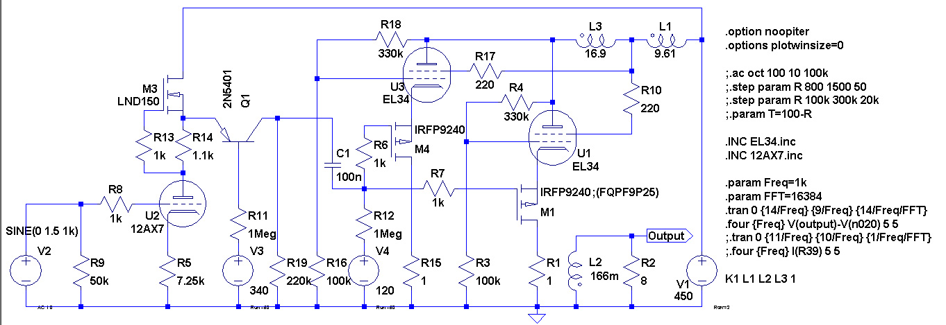
Well, I've done some tests and what it seems mandatory based on the simulations to get good results is:
- a CCS load for the input triode, in order to have a wide swing (around 100 Vpp) with a low THD;
- a mosfet driver, to be able to reach class A2 and squeeze some more power on peaks;
- a CCS load on the driver, to get a cleaner sound (I've loaded it with a 15k resistor but results are worst).
- local feedback on the power tube (UL + plate-to-grid + cathode feedback)
For those parts, nowadays SS seems the most logical solution, but I'm open to other possibilities.
What I can try is to drive the cathode of the EL34 and keep g1 fed by the voltage divider from the plate. It will need one CCS less. Like a CCS loaded triode, UNSET amp with UL and Cathode Feedback.
Is it safe for the speaker in case of any failure?
Rethinking about it, the driver has too much voltage across it, and this makes it dissipate too much heat. I will reduce the voltage across it to just 30V more on top and bottom of the needed swing.
Rereading some posts Tubelab wrote on another of my threads ( 450W bass amp: a sextet of GU50s with shunt¤t feedback ), I switched to something similar to his design with anode-to-grid feedback and cathode drive the output tube through a p-mosfet FQPF9P25: https://www.mouser.com/datasheet/2/149/FQPF9P25-110839.pdf
Then I optimized the CCS with the following design:
CCS PCB – Bartola(R) Valves
The optimized result will make 6A3sUMMER happier with a 3SS:2VT ratio, and me happier as well with the following results at 10 Wrms:
This is at 15 Wrms:
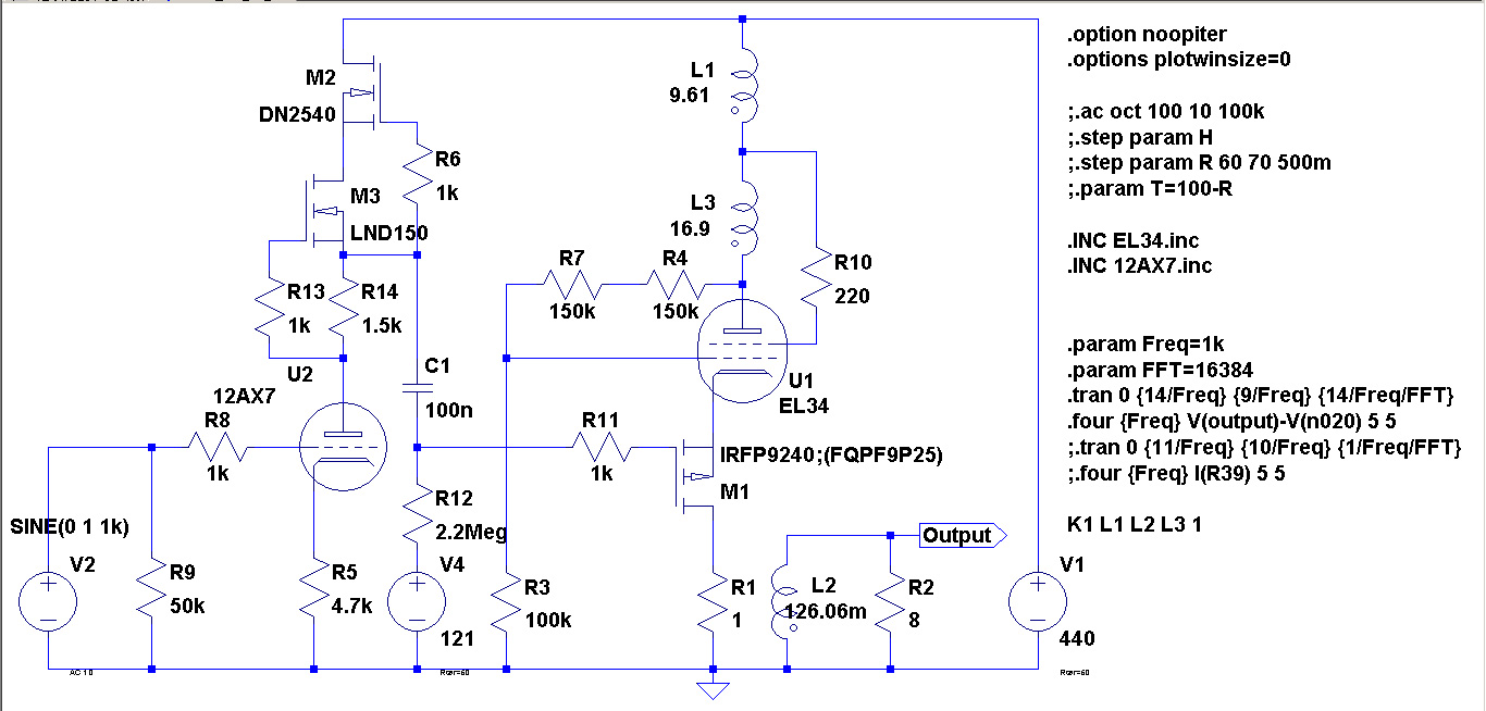
This is the schematic:
Then I optimized the CCS with the following design:
CCS PCB – Bartola(R) Valves
The optimized result will make 6A3sUMMER happier with a 3SS:2VT ratio, and me happier as well with the following results at 10 Wrms:
Code:
Harmonic	Frequency	 Fourier 	Normalized	 Phase  	Normalized
 Number 	  [Hz]   	Component	 Component	[degree]	Phase [deg]
    1   	1.000e+03	1.268e+01	1.000e+00	   -6.29°	    0.00°
    2   	2.000e+03	1.823e-01	1.438e-02	 -116.76°	 -110.47°
    3   	3.000e+03	5.289e-02	4.172e-03	    0.28°	    6.56°
    4   	4.000e+03	9.692e-03	7.646e-04	   32.01°	   38.30°
    5   	5.000e+03	7.364e-03	5.810e-04	  165.59°	  171.88°
    6   	6.000e+03	7.787e-04	6.143e-05	 -167.32°	 -161.04°
    7   	7.000e+03	1.232e-03	9.722e-05	  -31.73°	  -25.45°
    8   	8.000e+03	1.314e-04	1.037e-05	   11.93°	   18.22°
    9   	9.000e+03	1.773e-04	1.398e-05	  116.17°	  122.45°
Total Harmonic Distortion: 1.500431%(1.500431%)
This is at 15 Wrms:
Code:
Harmonic	Frequency	 Fourier 	Normalized	 Phase  	Normalized
 Number 	  [Hz]   	Component	 Component	[degree]	Phase [deg]
    1   	1.000e+03	1.567e+01	1.000e+00	   -6.37°	    0.00°
    2   	2.000e+03	3.513e-01	2.242e-02	 -116.79°	 -110.42°
    3   	3.000e+03	1.865e-01	1.191e-02	   -2.90°	    3.47°
    4   	4.000e+03	4.574e-02	2.920e-03	   40.71°	   47.08°
    5   	5.000e+03	6.083e-02	3.883e-03	  160.57°	  166.94°
    6   	6.000e+03	1.300e-02	8.295e-04	 -138.42°	 -132.05°
    7   	7.000e+03	2.263e-02	1.445e-03	  -38.64°	  -32.28°
    8   	8.000e+03	6.674e-03	4.260e-04	   41.80°	   48.16°
    9   	9.000e+03	8.740e-03	5.579e-04	  121.46°	  127.83°
Total Harmonic Distortion: 2.590974%(2.591252%)
This is the schematic:
Attachments
That looks very good Zintolo. The feedback to the grid is quite high (I think Tubelab typically uses a 10:1 resistor ratio from plate to grd and grid to ground), but sensitivity is still good enough. The pmosfet is running at ~12W so you will need good heatsinking. I see that you are using 50 ohm impedance for the B+. With a reasonable amount of capacitance in the power supply I think it would be much lower than this, with even better results.
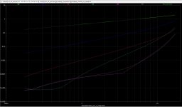
Some distortion results as a function of power output attached.
Some distortion results as a function of power output attached.
Attachments
Thanks Tikiroo,
I'm sure that more linear tubes like the KT77 or KT88 would perform better, but I have four matched EL34 that I would like to use them, and even with my PP amp I've used alot of local feedback (around 30%), wilst KT77 on simulations need way less local feedback to run linear.
I would like to implement Rod Coleman's shunt cascode driver ( Shunt Cascode Power Valve Driver and The Shunt Cascode Driver – Bartola(R) Valves ) that could also DC couple the preamp with the poweramp (as the power amp requires a positive voltage at the input of the pMOSFET).

I will do some simulations tonight, this way I should be able to implement feedback on the driver as well, and further improve the results.
I'm sure that more linear tubes like the KT77 or KT88 would perform better, but I have four matched EL34 that I would like to use them, and even with my PP amp I've used alot of local feedback (around 30%), wilst KT77 on simulations need way less local feedback to run linear.
I would like to implement Rod Coleman's shunt cascode driver ( Shunt Cascode Power Valve Driver and The Shunt Cascode Driver – Bartola(R) Valves ) that could also DC couple the preamp with the poweramp (as the power amp requires a positive voltage at the input of the pMOSFET).
I will do some simulations tonight, this way I should be able to implement feedback on the driver as well, and further improve the results.
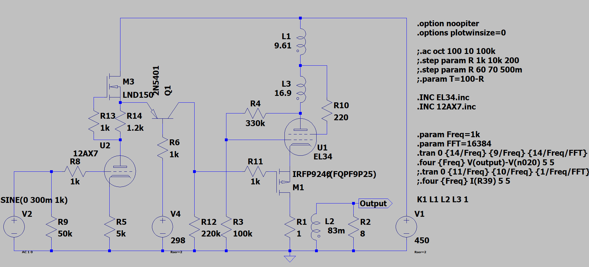
This is the file I will use to find sweet spots.
As is, results at 15 Wrms are:
At 10 Wrms:
At 1 Wrms:
As is, results at 15 Wrms are:
Code:
Harmonic	Frequency	 Fourier 	Normalized	 Phase  	Normalized
 Number 	  [Hz]   	Component	 Component	[degree]	Phase [deg]
    1   	1.000e+03	1.555e+01	1.000e+00	   -6.54°	    0.00°
    2   	2.000e+03	1.209e-01	7.776e-03	  168.06°	  174.60°
    3   	3.000e+03	2.847e-01	1.831e-02	   -2.10°	    4.45°
    4   	4.000e+03	3.268e-02	2.102e-03	  -14.26°	   -7.72°
    5   	5.000e+03	1.131e-01	7.277e-03	  158.12°	  164.67°
    6   	6.000e+03	1.143e-03	7.350e-05	 -122.66°	 -116.11°
    7   	7.000e+03	4.865e-02	3.129e-03	  -47.13°	  -40.59°
    8   	8.000e+03	1.030e-02	6.625e-04	   65.42°	   71.96°
    9   	9.000e+03	2.008e-02	1.291e-03	  107.81°	  114.35°
Total Harmonic Distortion: 2.156576%(2.159155%)
At 10 Wrms:
Code:
Harmonic	Frequency	 Fourier 	Normalized	 Phase  	Normalized
 Number 	  [Hz]   	Component	 Component	[degree]	Phase [deg]
    1   	1.000e+03	1.265e+01	1.000e+00	   -6.40°	    0.00°
    2   	2.000e+03	5.936e-02	4.692e-03	  148.94°	  155.34°
    3   	3.000e+03	6.957e-02	5.499e-03	    2.03°	    8.43°
    4   	4.000e+03	9.287e-03	7.339e-04	   -6.67°	   -0.27°
    5   	5.000e+03	1.048e-02	8.280e-04	  168.50°	  174.90°
    6   	6.000e+03	1.362e-03	1.076e-04	  100.57°	  106.96°
    7   	7.000e+03	2.026e-03	1.601e-04	  -35.82°	  -29.42°
    8   	8.000e+03	3.051e-04	2.411e-05	 -138.81°	 -132.42°
    9   	9.000e+03	4.001e-04	3.162e-05	  120.15°	  126.55°
Total Harmonic Distortion: 0.731506%(0.731506%)
At 1 Wrms:
Code:
Harmonic	Frequency	 Fourier 	Normalized	 Phase  	Normalized
 Number 	  [Hz]   	Component	 Component	[degree]	Phase [deg]
    1   	1.000e+03	4.168e+00	1.000e+00	   -6.30°	    0.00°
    2   	2.000e+03	6.066e-03	1.455e-03	  123.45°	  129.75°
    3   	3.000e+03	1.513e-03	3.630e-04	    1.39°	    7.69°
    4   	4.000e+03	6.056e-05	1.453e-05	   10.71°	   17.01°
    5   	5.000e+03	1.922e-05	4.611e-06	  175.87°	  182.17°
    6   	6.000e+03	4.376e-06	1.050e-06	  176.44°	  182.74°
    7   	7.000e+03	3.128e-06	7.505e-07	 -177.24°	 -170.94°
    8   	8.000e+03	2.965e-06	7.115e-07	 -178.31°	 -172.01°
    9   	9.000e+03	2.569e-06	6.164e-07	 -178.97°	 -172.67°
Total Harmonic Distortion: 0.150006%(0.150004%)
Attachments

Here it is the version with Rod's shunt driver and a PSE of two EL34s per channel capable of around 30-35 Wrms. Ra is 5k.
This are the results at 34 Wrms:
at 7.5 Wrms:
and at 1 Wrms:
This are the results at 34 Wrms:
Code:
Harmonic	Frequency	 Fourier 	Normalized	 Phase  	Normalized
 Number 	  [Hz]   	Component	 Component	[degree]	Phase [deg]
    1   	1.000e+03	2.329e+01	1.000e+00	  -10.85°	    0.00°
    2   	2.000e+03	3.933e-01	1.689e-02	  154.69°	  165.53°
    3   	3.000e+03	8.427e-01	3.618e-02	  -14.03°	   -3.18°
    4   	4.000e+03	1.829e-01	7.851e-03	 -122.38°	 -111.54°
    5   	5.000e+03	3.449e-01	1.481e-02	  123.83°	  134.68°
    6   	6.000e+03	8.533e-02	3.664e-03	  -42.59°	  -31.75°
    7   	7.000e+03	1.125e-01	4.830e-03	 -105.71°	  -94.87°
    8   	8.000e+03	6.544e-02	2.810e-03	   38.92°	   49.77°
    9   	9.000e+03	2.037e-02	8.745e-04	   22.91°	   33.76°
Total Harmonic Distortion: 4.382518%(4.388086%)
at 7.5 Wrms:
Code:
Harmonic	Frequency	 Fourier 	Normalized	 Phase  	Normalized
 Number 	  [Hz]   	Component	 Component	[degree]	Phase [deg]
    1   	1.000e+03	1.103e+01	1.000e+00	  -10.25°	    0.00°
    2   	2.000e+03	3.990e-02	3.619e-03	  179.18°	  189.42°
    3   	3.000e+03	2.196e-02	1.992e-03	  -10.33°	   -0.09°
    4   	4.000e+03	1.407e-03	1.276e-04	  -38.65°	  -28.40°
    5   	5.000e+03	7.390e-04	6.703e-05	  151.49°	  161.74°
    6   	6.000e+03	6.178e-05	5.603e-06	   71.07°	   81.31°
    7   	7.000e+03	2.963e-05	2.688e-06	  -86.36°	  -76.12°
    8   	8.000e+03	1.610e-05	1.461e-06	 -178.81°	 -168.56°
    9   	9.000e+03	1.040e-05	9.434e-07	  171.21°	  181.46°
Total Harmonic Distortion: 0.413337%(0.413336%)
and at 1 Wrms:
Code:
Harmonic	Frequency	 Fourier 	Normalized	 Phase  	Normalized
 Number 	  [Hz]   	Component	 Component	[degree]	Phase [deg]
    1   	1.000e+03	4.018e+00	1.000e+00	  -10.21°	    0.00°
    2   	2.000e+03	4.714e-03	1.173e-03	  176.40°	  186.60°
    3   	3.000e+03	9.380e-04	2.335e-04	  -11.36°	   -1.15°
    4   	4.000e+03	1.571e-05	3.909e-06	  -42.90°	  -32.69°
    5   	5.000e+03	8.800e-06	2.190e-06	  169.08°	  179.29°
    6   	6.000e+03	4.598e-06	1.144e-06	  179.04°	  189.24°
    7   	7.000e+03	3.930e-06	9.781e-07	 -179.62°	 -169.41°
    8   	8.000e+03	3.494e-06	8.696e-07	  180.00°	  190.20°
    9   	9.000e+03	3.060e-06	7.615e-07	 -179.68°	 -169.47°
Total Harmonic Distortion: 0.119625%(0.119622%)
Attachments
Good idea direct coupling the shunt cascode to the pmos, but you've dropped that now? I can't look at the simulation at the moment but a couple of things come to mind:
- you need r14 to be a trimpot as current through the 12ax7 will vary with the tube, and you need to make sure that there is the correct total current split between the tube and R19 cascode resistor
- R19 at 220k is very high ( and current low) considering you are driving the input capacitance of 2 pmos in parallel. Only driving Crss as the pmos is acting as a follower but might pay to check performance at higher frequency and/or use a low capacitance pmos
-12ax7 not the best choice for shunt cascode, can be better to use a higher gm tube running at higher current, but might be OK in this application
- Voltage source for cascode (V3) must be very low noise. Why is the 1 Meg resistor R11 there?
Hi tikiroo, I abandoned the dc coupling because the bias point was too unstable. As Rod suggested somewhere, an inductor could fix the bias and avoid the coupling cap. This is another option.
I'd use both R14 and R15 as trimpots, to find the best current and working point of the tube.
I agree with you that the 12AX7 is not the best tube for the purpose, but I've tried the ECC88 and I wasn't able to get the same gain. If you have other options, I'll be very happy to try them and reduce R19.
I moved R11 from a previous circuit instead of pressing R and didn't change its value. It was supposed to be 1 kOhm.
Roberto, it's a creative use of the circuit, bravo. There are some practical problems: the 3 that Tikaroo mentions (which all need attention) plus some from me:
- Q1 emitter must be connected to the driver tube anode, directly. Or else it's not completely a cascode!
- 450V unregulated supply will probably mean failures of the LND150 quite often. and the high voltage makes it difficult to choose a good cascode transistor. It's much better to choose a tube that runs at 150V and use a 170V supply. It will give plenty of drive for EL34s.
- A follower made with one of the new ST super-low Crss FETs will solve the P-ch FET driving problem.
- the cascode voltage regulator needs to have low output impedance and low noise, and wide bandwidth.
These practical problems are what my upcoming version of the Shunt Cascode will tackle, and will also add a DC servo, to avoid setup hassle and DC drift.
Thank you Rod!
I'm looking forward to your new pcb since you talked me about the added features.
Good catch the Q1 emitter to tube anode, thanks!
Will a cascoded DN2540 on top of the LND150 help to protect it (and improve the CCS as well) from a non perfect PSU?
As for the voltage, I need really alot of swing in this application, because I've 23% local feedback on anode to grid, that means 23% of 850Vpp swing, so around 200Vpp added to the standard 60-70 Vpp needed to drive the tubes. That's why I went to 340Vdc, that is also close to 12AX7 recommended maximum plate voltage.
Is there anything that can be safely used?
If there's any other noval twin triode high gm tube that I can use with higher currents and lower load resistors, I'd be happy to implement them.
Oh, I will use elevated heaters at 100V to be sure not to exceed tubes h-k limits.
I will check with Tubelab the new ST fets, as I remember him saying that the choice of the pMosfet was highly dependant on its reliability in this application.
So even the 1k could be too much for R11, and an high voltage regulator could be a better option.
Thank you all in advance!
Roberto
Anode to grid feedback is great to reduce the source impedance for the output transformer and reduce distortion, but you could probably dial it back to more normal levels and add some global feedback instead so you don't have the huge swing requirement.
If there's any other noval twin triode high gm tube that I can use with higher currents and lower load resistors, I'd be happy to implement them.
ECC99?
Keep in mind that with Shunt Cascode, the valve's anode does not swing any voltage. It only swings current.
This is the root of its many advantages, like zero miller effect - very gentle load for the signal source.
It also means that you can operate the anode at 100-150V (whatever is the optimum for the valve) and still get big output swings, simply by returning the load resistor to a negative voltage.
Many of the best frame-grid high-gm triodes are at their best at 150V, so this is a good choice. Low anode voltage also means that you can run the anode current high, and get lower distortion.
@ tikiroo:
thanks, I will try the ECC99 and the gnfb too. On my PP amp I'm planning to implement a variable gnfb (limited in the maximum amount of gnfb by a resistor in series with the pot) and I could do the same here.
@Rod Coleman: thank you very much! I always saw the voltage at the base of Q1 as a limit, and never thought about referring the load to a negative voltage to obtain more swing. Fantastic!
Thank you both!
Looking at this datasheet of the ECC99 ( http://www.amplimos.it/images/ECC99.pdf ) am I correct saying I can set the voltage at 150 V and the current at around 30 mA?
Is there a similar tube but less current demanding?
Is there a similar tube but less current demanding?
- Home
- Amplifiers
- Tubes / Valves
- Chinese Single Ended 12AX7+EL34: improvements?