Thanks mike567,
https://www.jj-electronic.com/images/stories/product/preamplifying_tubes/12bh7_a/12BH7-A.pdf
Like 150V and 20 mA? That's ok for the plate dissipation, but on the limit for Ik.
https://www.jj-electronic.com/images/stories/product/preamplifying_tubes/12bh7_a/12BH7-A.pdf
Like 150V and 20 mA? That's ok for the plate dissipation, but on the limit for Ik.
The way to have a poor tube amp, in my opinion.
No test lab that can ceritfy the performances! This is the major problem of this tye of kit ( and in general)
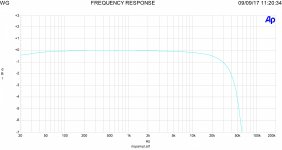
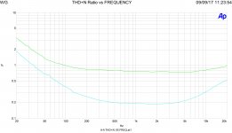
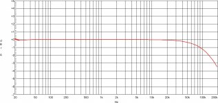
Jut to be clear, in attach a circuit, simply and certified.
With freq. answer and thd vs frequency with two different I bias.
The trafo are custom but also with Hammond is possible to get a good results
Walter
No test lab that can ceritfy the performances! This is the major problem of this tye of kit ( and in general)
Jut to be clear, in attach a circuit, simply and certified.
With freq. answer and thd vs frequency with two different I bias.
The trafo are custom but also with Hammond is possible to get a good results
Walter
Attachments

Thank you Mike!
I've found the datasheet: https://frank.pocnet.net/sheets/113/6/6N1PEV.pdf
I will see if there are some LTSpice models of it, in order to implement it.
I've found the datasheet: https://frank.pocnet.net/sheets/113/6/6N1PEV.pdf
I will see if there are some LTSpice models of it, in order to implement it.
6N1P spice model
* Generic triode model: 6N1P_AN
* Copyright 2003--2008 by Ayumi Nakabayashi, All rights reserved.
* Version 3.10, Generated on Sun Jan 12 18:59:00 2014
* Plate
* | Grid
* | | Cathode
* | | |
.SUBCKT 6N1P_AN A G K
BGG GG 0 V=V(G,K)+-0.42063507
BM1 M1 0 V=(0.007566675*(URAMP(V(A,K))+1e-10))**-0.43818786
BM2 M2 0 V=(0.77391879*(URAMP(V(GG)+URAMP(V(A,K))/29.878541)+1e-10))**1.9381879
BP P 0 V=0.0022884667*(URAMP(V(GG)+URAMP(V(A,K))/38.606817)+1e-10)**1.5
BIK IK 0 V=U(V(GG))*V(P)+(1-U(V(GG)))*0.0013346379*V(M1)*V(M2)
BIG IG 0 V=0.0011442333*URAMP(V(G,K))**1.5*(URAMP(V(G,K))/(URAMP(V(A,K))+URAMP(V(G,K)))*1.2+0.4)
BIAK A K I=URAMP(V(IK,IG)-URAMP(V(IK,IG)-(0.001233721*URAMP(V(A,K))**1.5)))+1e-10*V(A,K)
BIGK G K I=V(IG)
* CAPS
CGA G A 1.6p
CGK G K 3.2p
CAK A K 1.5p
.ENDS
Thank you so much euro21!
This evening I will perform some tests with that tube too!
I need also to calculate what is a reasonable limit for the load resistor in order not to limit the bandwidth and the current not to limit the slew rate as well.
This evening I will perform some tests with that tube too!
I need also to calculate what is a reasonable limit for the load resistor in order not to limit the bandwidth and the current not to limit the slew rate as well.
The 6N1P is not a proper tube to do that job.
The gain is similar to 6922/6H23 but the Rp in greater and Gm is lower,
Much better the 6922 in Srpp so it can swing a good voltage with low Zout and reasonable low distortion.
Another good solution is 5965 always in Srpp.
And leave the simulation, the real world is different from virtual.
Try to use the solder and stuff.
Walter
Ciao Walter,
thanks to suggest the 6922, I've found the models here and will simulate it as well: Vacuum Tube SPICE Models
I'm not interested in the SRPP because it hasn't enough swing for the specific purpose.
Do not assume by preconcept that people do not experiment with the solder just because they are into simulations. I support the solder with simulations, as I've found it to be a faster way to get results I like. YMMV.
I will report how the 6922 will work with this specific circuit.
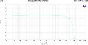
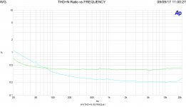
Are you sure about swing with 6922?
I think you haven't test it in a right way.
In attach the real test on Srpp of the circuit sent post ago
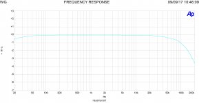
With 450 mV in you got 20 Vout rms with a BW of around 200 kHz and distortion less than 1%; in this way the grid of EL34 or KT88 will be driven good
This is E88C, single triode
In addition a freq. response of a Srpp withh 6922, 1 Vin, 23 Vout,
I have a lot of preconcept about simulation until the real circuit is done with real test.
And the comparison is verified.
When there are involved the trafos and inductors this is not possible
Walter
I think you haven't test it in a right way.
In attach the real test on Srpp of the circuit sent post ago
With 450 mV in you got 20 Vout rms with a BW of around 200 kHz and distortion less than 1%; in this way the grid of EL34 or KT88 will be driven good
This is E88C, single triode
In addition a freq. response of a Srpp withh 6922, 1 Vin, 23 Vout,
I have a lot of preconcept about simulation until the real circuit is done with real test.
And the comparison is verified.
When there are involved the trafos and inductors this is not possible
Walter
Attachments
Last edited:
Thanks for your comment Walter,
if you look at the circuit I've posted, I have a cathode driven output tube à la Tubelab with local feedback anode-to-grid. That causes to add the swing of the grid (that is a percentage of the anode swing) to the driver's swing. That's why I went to Rod Colemans' shunt driver, that working on a vertical load line is able to swing 100 Vrms with a THD lower than 1 and mainly 2nd harmonic (due to the knee at the bottom of the curves).
if you look at the circuit I've posted, I have a cathode driven output tube à la Tubelab with local feedback anode-to-grid. That causes to add the swing of the grid (that is a percentage of the anode swing) to the driver's swing. That's why I went to Rod Colemans' shunt driver, that working on a vertical load line is able to swing 100 Vrms with a THD lower than 1 and mainly 2nd harmonic (due to the knee at the bottom of the curves).
Why you are looking for a complicate life?
30-35 wrms? with 4,3% of THD, It is a joke?
How much is the thd at low freq. and high freq? 30%?
In which way you can simulate the trafo if you aren't able to get the real parameters of it?
At mid frequency is possible to assume that the trafo is quite ideal but at the ends is another story,
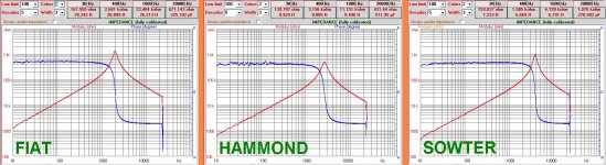
In attach three different s.e, trafo under test.
The test is done with a particular sw by Fabrizio Montanucci in Audioreview magazine in Italy where I write .
It is possible to measure the inductors and caps.
You can see the differences on each one.
The shape of Z in function of frequencies.
As you see the resonance varies between 2 kHz and 3 kHz with different Q.
After the resonance the phase switch from +90 to -90° this because the trafo is acting, less or more, as capacitor (due the parasitic)
In which way you can simulate this?
These are the real problems in tube amps.
Not the swing at 100 Vrms that is not necessary in your case
And the use of sand while you can reach a very good results in other simply way also to spent money for OT
Walter
30-35 wrms? with 4,3% of THD, It is a joke?
How much is the thd at low freq. and high freq? 30%?
In which way you can simulate the trafo if you aren't able to get the real parameters of it?
At mid frequency is possible to assume that the trafo is quite ideal but at the ends is another story,
In attach three different s.e, trafo under test.
The test is done with a particular sw by Fabrizio Montanucci in Audioreview magazine in Italy where I write .
It is possible to measure the inductors and caps.
You can see the differences on each one.
The shape of Z in function of frequencies.
As you see the resonance varies between 2 kHz and 3 kHz with different Q.
After the resonance the phase switch from +90 to -90° this because the trafo is acting, less or more, as capacitor (due the parasitic)
In which way you can simulate this?
These are the real problems in tube amps.
Not the swing at 100 Vrms that is not necessary in your case
And the use of sand while you can reach a very good results in other simply way also to spent money for OT
Walter
Attachments
Walter, I appreciate your warnings but please go off the pulpit, thanks.
That behaviour is ruining the thread.
If you are not interested in implementing SS in tube amps (and this is clear), this doesn't mean all others don't have to.
If you are not interested in simulate tube amps (and this is clear too), this doesn't mean all others don't have to, as a starting point.
Please, be kind. Your point is clear.
Let us kids play with sand.
I have read your first post.
This is why I have wrote some consideration.
And there isn't pulpit; there are technical aspect that must be take in consideration that you can't resolve with simulation.
You can use all the sand you want and all simulation, of course.
Let me to criticize in the proper way.
Bye
Walter
This is why I have wrote some consideration.
And there isn't pulpit; there are technical aspect that must be take in consideration that you can't resolve with simulation.
You can use all the sand you want and all simulation, of course.
Let me to criticize in the proper way.
Bye
Walter
The way to have a poor tube amp, in my opinion.
No test lab that can ceritfy the performances! This is the major problem of this tye of kit ( and in general)
Jut to be clear, in attach a circuit, simply and certified.
With freq. answer and thd vs frequency with two different I bias.
The trafo are custom but also with Hammond is possible to get a good results
Walter
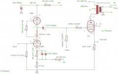
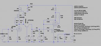
Looks like a simple elegant circuit. What do you think about substituting 2X 6L6 tubes instead of the KT150?
Attachments
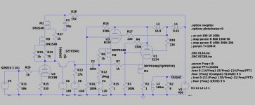
Instead of doing the coffee break I switched the input tube to a ECC88 with good results, but I still have a predominant 2nd harmonic even at low power.
I only simulated the version with one output tube, because that's the version I have on the laptop I'm using now. This evening I will simulate the PSE.

These the results at 15 Wrms:
I only simulated the version with one output tube, because that's the version I have on the laptop I'm using now. This evening I will simulate the PSE.
These the results at 15 Wrms:
Code:
Harmonic	Frequency	 Fourier 	Normalized	 Phase  	Normalized
 Number 	  [Hz]   	Component	 Component	[degree]	Phase [deg]
    1   	1.000e+03	1.535e+01	1.000e+00	   -0.87°	    0.00°
    2   	2.000e+03	3.526e-01	2.297e-02	  -95.93°	  -95.07°
    3   	3.000e+03	1.923e-01	1.253e-02	    1.45°	    2.32°
    4   	4.000e+03	3.760e-02	2.449e-03	  -73.00°	  -72.13°
    5   	5.000e+03	6.268e-02	4.083e-03	 -177.46°	 -176.60°
    6   	6.000e+03	2.505e-02	1.632e-03	   98.60°	   99.47°
    7   	7.000e+03	2.381e-02	1.551e-03	    2.95°	    3.82°
    8   	8.000e+03	9.736e-03	6.343e-04	  -78.84°	  -77.98°
    9   	9.000e+03	7.239e-03	4.716e-04	 -174.04°	 -173.17°
Total Harmonic Distortion: 2.669876%(2.669969%)
Attachments
I have one question about SE amps: it is preferrable to hit Vg1=Vk before Ik=0, or the opposite?
I would say the former, because you still have control on the speaker due to the high current flowing through the tube, otherwise with no current on the tube the speaker is no more controlled, but that's just my guess and I could be wrong.
Thanks
Roberto
I would say the former, because you still have control on the speaker due to the high current flowing through the tube, otherwise with no current on the tube the speaker is no more controlled, but that's just my guess and I could be wrong.
Thanks
Roberto
Looks like a simple elegant circuit. What do you think about substituting 2X 6L6 tubes instead of the KT150?
Hu
I use it with EL34, Kt88, also 300B, never for parallel but the Zout and swing of srpp with E88c is fine for that use.
It is incredible as this triode is very good; and the price is not so high for a nos/nib
On the circuit the Fb is only 6dB
Walter
Last edited:
I'm looking at the datasheet of the FQPF9P25 ( https://www.mouser.it/datasheet/2/308/FQPF9P25-D-1809691.pdf ) and here I have a limit on the Vds that could make me move towards the FQPF9N50 ( https://www.mouser.it/datasheet/2/308/FQPF9N50CF-D-1810101.pdf ) or reduce the local feedback on the EL34s.
By the way, this is the circuit with two EL34s in parallel.

and these the results at 30Wrms:
By the way, this is the circuit with two EL34s in parallel.
and these the results at 30Wrms:
Code:
Harmonic	Frequency	 Fourier 	Normalized	 Phase  	Normalized
 Number 	  [Hz]   	Component	 Component	[degree]	Phase [deg]
    1   	1.000e+03	2.165e+01	1.000e+00	   -1.66°	    0.00°
    2   	2.000e+03	4.459e-01	2.059e-02	 -100.93°	  -99.27°
    3   	3.000e+03	2.672e-01	1.234e-02	    4.76°	    6.43°
    4   	4.000e+03	8.060e-02	3.722e-03	  -72.40°	  -70.74°
    5   	5.000e+03	9.459e-02	4.368e-03	 -174.10°	 -172.44°
    6   	6.000e+03	4.972e-02	2.296e-03	   97.96°	   99.62°
    7   	7.000e+03	3.956e-02	1.827e-03	    3.07°	    4.73°
    8   	8.000e+03	2.149e-02	9.923e-04	  -87.12°	  -85.46°
    9   	9.000e+03	1.436e-02	6.630e-04	  177.01°	  178.67°
Total Harmonic Distortion: 2.488472%(2.488905%)
Attachments
Hu
I use it with EL34, Kt88, also 300B, never for parallel but the Zout and swing of srpp with E88c is fine for that use.
It is incredible as this triode is very good; and the price is not so high for a nos/nib
On the circuit the Fb is only 6dB
Walter
Only the E88C? Doesn't seem too common.
What is the DC elevation for the heaters?
- Home
- Amplifiers
- Tubes / Valves
- Chinese Single Ended 12AX7+EL34: improvements?