Mundorf MCoil VN300 Zero -Ohm or Jantzen C-Coil ?

the mundorf VN300 don't seem to be as "famous" as jantzen C-coil
here the mundorf: MCoil VN300 Zero-Ohm-Core | Mundorf EB GmbH
very poor description.
here the jantzen:
http://www.jantzen-audio.com/wp-content/uploads/2020/06/C-Coil-Data.pdf
http://www.jantzen-audio.com/wp-content/uploads/2020/05/C-Coil-Values.pdf
detailed description

the value i'm intrested is 4.7mH and i would to know the main techincal differences between them to choice which is better ?

the mundorf seems to be more bigger and more expensive but the transformer tech is better the toroidal or no ?

someone could help me ?
thank you very much

Dual PSU considerations in F5 amp

Hello all - I am new to this forum and to DIY audio and it looks like I’m in the right place for a little help and advice. So, I’ve managed to gather everything I need (I think) and will soon begin my first build, the First Watt F5. It’s taken some time acquiring everything, including the two 250va toroids and dual unregulated PSU boards for the project. I went this way because A., DIY Audio was out of stock for the boards at the time, B., I wanted to have plenty of power as a foundation for this initial build and C., I couldn’t readily find a 5-600VA toroid with called for specs at a reasonable price. So “dual-mono” PSUs seemed the way to go.

My questions - which are surely elementary and easily answered, although several hours spent searching this forum hasn’t been fruitful. So here goes:

1. I plan to connect both primaries of the xfmrs to the common input line, with both hots running through the same switch and through the same soft start module I intend to use, which specs more than ample capacity for this application. The soft start circuit will, in addition to managing initial cap charging inrush current, allow me to use a momentary “standby” push-button on the front of the amp. I’m not sure whether using this device will negate the need for the CR60 thermistors at the input - aren’t these also intended to limit current during startup?

2. Are there any other commonalities between the two xfmrs/psus I need to consider for this scheme? I am assuming that grounds will be common between the two psus, is there anything else I need to consider with respect to, I don’t know...keeping the psus in “sync” or something like that, maybe to compensate for slight irregularities between the two xfmrs or psu circuits? I suppose I had just planned to treat each amp channel/psu as completely separate entities (so to speak) with the only commons being at the high side input and the common DC grounds.

Anything else I might should be thinking about with regard to the power supply scheme for this amp? I’m using 80kuf per side for filtering, which I hope will be more than sufficient - I’m not inclined to do all the ripple math and stuff, in favor of just going big on the filtration!

Thanks in advance for any guidance or advice you could provide here!

R, Phil

Sub-extension for zaph zd 5

Hello there 🙂
A few weeks ago i built the zaph zd5. I am very pleased they sound great. Very clear and neutral. After comparing them with my canton digital 1 with 2 10 inch woofers each and capability of reaching down to the 20 hertz region i began to miss the feeling of power of the big canton towers in the sub range. The zd5 make a fool out of the cantons in every other aspect though.

Now i have begun to do some research and stumbled upon troels ellam flex 3w with the addition of his bass cabs.
Ellam-FLEX-3W
He uses the same mid woofer the 15w/8530 k00 so my first thought was to use the same woofer drivers as he does. They are however a bit pricey.
Ive also looked at some gr research servo controlled subwoofer kits.

As i see it i have a two options.
Build two bass extension cabs that i can cross between 100-200 hertz und play down depending on the woofers and their price to the 30 hertz region.
An 8 or maybe even 10 inch driver.

Or build one good subwoofer maybe a gr research servo controlled one or buy a rhytmik l12 even though both of these would cost me around 700 bucks.

The sub would go lower but troels mentioned that with his bass extension he gets a better („more powerful“ maybe he means max spl?) response from 200 hertz downwards.

What kind of solution do you prefer and or think is better? My listening room is rather small around 45-50 qubic metres i think.

Also what do you think would be a good sub driver for this experiment that are around 200 usd or less. Ive seen a local ad for two 21w/8555-01 for 90 usd each.

Thanks in advance for all your help 🙂

NAD 7225PE schematic question re: polarity

Hi All,

I have a NAD7225PE and have decided to undertake a recap. I have noticed C601 and D602 are missing from the amp and a wire is connected from the negative side of C601 to the base of R14. refer attached. My question is does this look correct on the schematic ? Is the polarity as marked on the schematic incorrect ? i.e. positive to gound ?

Any comments appreciated. I started to put a capacitor and diode where they are missing but I am not too sure I should, at least as the polarity is shown anyway.

Richard

Attachments

Should I use 100 ohm resistor to "lift ground"

(Below I am talking about putting a 100 ohm resistor between the preamp output jack and ground, "lifting the ground" of the signal to prevent ground loop hum. I am not referring to taking the ground off the power cable.)

Hi all thanks for looking. I was building a preamp, and I was considering putting an optional ground switch on my output. In my study of schematics, I looked at different guitar amplifier schematics. For example, I was reading the Marshall JCM 900 schematic to see what they did.

Rather than putting a ground lift switch on the effects send, the direct out, and the "recording compensated, (ie speaker simulator/voiced/filtered), they simply placed a 100 ohm resistor on all grounds preemptively.

My question is, should I put no ground lifts, ground lift switch, or preemptively place a ground lift resistor?

Can having a 100 ohm ground lift resistor that is not needed cause problems?

Thanks anyone for your experience and expertise.

CD player muting circuit

Hi All,


Can someone please explain how's the CD players outputs muting function works in the attached drawing?
I have a CD player with an issue, there is no sound output at all but after I removed the 2 transistors Q301/Q302 I get audio perfect output the only issue is that when the CD player is switched off I get white noise from it's outputs.


Thanks

Attachments

  • Output mute.jpg
    Output mute.jpg
    116.9 KB · Views: 766

Bias Current Compensated Op Amps, What do they mean for Offsets?

Was reading Walt Jung, Op Amp Applications Handbook, and something blew my mind, as usual.

It is also a well-known fact that, within an op amp application circuit, the effects of bias
current on the output offset voltage of an op amp can often be cancelled by making the
source resistances at the two inputs equal. But, there is an important caveat here. The
validity of this practice only holds true for bipolar input op amps without bias current
compensation, that is, where the input currents are well matched. In a case of an op amp
using internal bias current compensation, adding an extra resistance to either input will
usually make the output offset worse!

In many cases, the bias current compensation feature is not mentioned on an op amp data
sheet, and a simplified schematic isn't supplied. It is easy to determine if bias current
compensation is used by examining the bias current specification. If the bias current is
specified as a "±" value, the op amp is most likely compensated for bias current.

Note that this can easily be verified, by examining the offset current specification (the
difference in the bias currents). If internal bias current compensation exists, the offset
current will be of the same magnitude as the bias current. Without bias current
compensation, the offset current will generally be at least a factor of 10 smaller than the
bias current. Note that these relationships generally hold, regardless of the exact
magnitude of the bias currents.

And sure enough, it seems like most op amps people like for audio are bias compensated. OP27 obviously, but it appears that OPA828, OPA134, OPA1611, LT1028... All have bias currents and offset currents in the same magnitude ballpark as Walt describes, and bias currents listed with +/-.

So what does this mean for impedance balancing resistors and even more curiously, balancing capacitors? Should these inputs simply be tied to ground instead, if you're using a bias compensated op amp?

As an example, I'm building an RJM phonoclone for a friend, and I am getting just a few mV less offset from it when I ground both R1 and R4. (In real life not SPICE) Any reason not to just ground them?
PhonoClone.png


Also does
The validity of this practice only holds true for bipolar input op amps without bias current compensation
mean there is no point trying to balance FET op amps?

Thanks.

Repair a VU Meter

I have a pair of UREI 1176LN. Classic audio compressor limiters. I replaced one of the VU meters recently due to failure. But the replacement is from an earlier version and the pair look different now. I would love some advice, tips, on how to repair this. It is a Modutec 'Lightbox' type. Taut band suspension. The problem was sticking. The needle clearance looks fine, but the coil seems to be offset.
attachment.php

Attachments

  • VU.jpg
    VU.jpg
    130.3 KB · Views: 4,677

Grounded cathode stage THD reduction with active load

I’m using a 12AT7 grounded cathode gain stage with an HT of 150V. This is giving me around 0.35% THD. Simulation and test results are in rough agreement.

I thought I’d play around with active loading as described in Morgan Jones’ “Valve Amplifiers” to see if I could get a worthwhile reduction in THD.

Operating point of the 12AT7 should be in the vicinity of Va 118V, Vg -1V and Ia 1.75mA as shown in the first picture below.

I put together a simulation as shown in the second picture which is based on figure 2.56 of “Valve Amplifiers” 4th edition. I’ve attached the simulation file.

I was expecting to see an order of magnitude reduction in THD. Instead, the simulation is reporting 0.46% which is higher than the standard stage simulation and test.

Why is the simulation not reporting a significant improvement in THD?

Attachments

  • 12AT7 with 1.75mA loadline.png
    12AT7 with 1.75mA loadline.png
    159.9 KB · Views: 329
  • Gain stage with MJ Fig 2.56.asc
    Gain stage with MJ Fig 2.56.asc
    3.2 KB · Views: 59
  • 12AT7 with cascode load.png
    12AT7 with cascode load.png
    17.5 KB · Views: 341

Bottlehead Seduction and Eros schematics

Does anyone have schematics of the Bottlehead Seduction and Eros preamp?
These preamps seem to have a good reputation,
and I am starting to work on a R2R head preamp and am looking around for ideas.

So if anyone have a link or is able to scan those schematics for me that would would be very helpful.

Other interesting tape head preamp schematics are welcome, of course 🙂

Single-Ended Tube Amp speaker matching question...

Hi all,

I'm not a tech, but appreciate that most of you on this forum are.

With that being said, I've recently acquired some big vintage Sansui SP-5000 speakers. I've done a full re-cap (the limit of my tech knowledge/ abilities) and am wondering about the suitability of tube amplification for these?

I know that low powered single ended amps can sound sweet with big vintage speakers due to there high sensitivity. The Sansui's are a very healthy 102dB@1w/1m. However, would a small SE Tube amp with 6w be okay to power these, as there are 7 drivers in each cabinet? Would all these drivers influence the amplifiers ability to drive them properly? Could I damage the drivers or the little amplifier with this kind of speaker?

Many thanks for any advice given in advance!

Clarion APC480M Very faint audio

I've been looking through the service manual for this amp, but just cant seem to pin-point where the audio signal is not getting to. This is a 4-channel amp similar to the APA4320.

Using my Honeytone referencing non-bridging terminals, I sense audio signal on Q24 and Q22 pre-driver MPSA06/56. Each channel has a set similar. All 4 channels I can observe audio on some of the pre-drivers. There is barely any output at speaker terminals however and while my honeymoon can sense something, hooking up a regular 4-ohm speaker doesn't produce any output at all.

Things I've checked.
Amp is gettin getting +-32vRail
Regulators are working +-16.7v
No opamps are producing anything significant at outputs, though some of the outputs have no audio on them. I did change out a few of the OpAmps but that didn't help.
Amp controls seem to be working as I can sense gain changes at the MPSA06/56 at the front of the drive circuits.

Each channel of this amp has quite a few driver transistors all seem to be testing out alright.

Any clues or direction?

Suitable Enclosure for TB W5 1611 SAF

Hello World
I decided not to follow my own advice and purchased these off a local speaker builder who made me an offer too good to refuse. I must say I was underwhelmed initially but after experimenting with larger baffles and giving them a day or two to break in. they sound very smooth, phase coherent and convince me there is is something to this full range driver stuff. The build quality is excellent for the money. 60 Hz FS is a bit high but you can't have it all for this money. They do have a certain coloration due to the polypropolene cone. I do prefer the sound of a good paper cone because I like that coloration better. Over all I am not sorry at all that I purchased these. Looking for advice for a cabinet or Horn to suit them. I already have a hybrid TL cab design that I know will work well with the modified lower QTS due to the neodymium backing magnets that sweeten the treble. If there is anyone out there who has put these into a front loaded horn I would love to hear from you. The Le Cleach Azura really appeals to me and I like the http://www.hornlautsprecher.de/ website but haven't got a handle on the theory as yet. Has anyone out there built a horn for these and what are their opinions?
Cheers and many thanks. Mark

Best current KT88? Plus TSE-II build & “Engineer” Solder Sucker

First, best wishes to George.

Look like it’s open season on 67 year-olds; I “popped a gut-string” about 2 mos ago (building a little bungalow on the Texas Coast, doin’ SUMTHIN I shouldn’ta been doing). Direct Inguinal Hernia. Surgery 3 weeks ago, still kinda whupped... this sure is No Country for Old Men...

Question: what’s the best current production BUDGET KT-88?
“Budget” meaning no more than about $50/ tube...Genelex Gold Lions look good, but is there something better?

I just realized that I set-up my shop amp for higher voltage (450-500vP) w/NOS Thordarson PST (about 820v at 200mA) and large swinging choke. To get low 400 vP, I have to use a 16uF choke input, so there’s plenty of EMF in reserve; figure I might as well use it. Only limitation is the G-series 5K EDCOR OPTs, but those can be upgraded if “required”.

In other news, got a pair of TSE-II boards from George today.
One is going in a 45 amp with 5K Transcendars from stock. Last night, I slapped some scraps of ash veneer on an old Baltic birch chassis. So far so good; now WOM (waiting on Mouser).

In still MORE news, got one of those “Engineer” plunger type solder suckers, cause I have 5 or 6 circuits that need dissection. Was gonna spring for a vacuum pump type, maybe even a Hakko to match the soldering station; that would have been a mistake. The “Engineer” solder sucker “works a treat” as my Limey buddies say. Gets about 80% average on first shot. No more screwing around trying to get solder wick to wet-out. Highly recommended.

Trying to finish my mtm style speakers

Hi so this is my first time asking for advice on here, ive been a lurker for a while but im literally at my wits end with my speaker build, so im hoping someone can help me to finally finish this.

Ive had some really great help from someone on another forum, i wouldnt have gotten this far without him tbh but i think hes too busy at the minute to walk me through everything, and i hate to keep repeatedly bothering someone with my problems

So basically ive designed an mtm using two pc83-4 woofers and a td20f-4 tweeter for use in my home cinema system, i wired the woofers in series and connected the tweeter in parallel. I bought the dats system and the omnimic so that i could take my own in box measurements but had a big issue with that at the start, my computer was affecting the tracks that were played and giving me false readings, that is sorted now, i think. My measurement method was as follows,

I set the mic 16" away on the centre of the tweeter, then took 3 sets of measurements without moving anything or changing the amp volume, they were the tweeter playing alone, then the woofers in series, then the woofers and the tweeter all together. I took those to find the z offset in xsim and it turns out its around 0.7. My issue now is that ive been advised that i should use the 'woofer in series' frd file in xsim to create the crossover, but im literally so confused by that, How do i add the frd files of two woofers playing in series into two separate simulated drivers in xsim? Every time i try it i end up with 16ohms impedance because it thinks each simulated driver is 8 ohms, but theyre not, i need them to read as 4 ohms. I cant continue with the crossover until i figure this out, i managed to get somewhere with it using the frd i created when i measured just one of the woofers instead of them in series, as i can add the files in the same way i do with the downloaded manufacturers frd files but like i said ive been advised to do it differently. I apologize if this post is a bit confusing, but id really appreciate any help with this and the crossover i eventually plan to design.

CheapoModo: quick and dirty transformer snubber bellringer jig

A high quality test-jig called Quasimodo has been described on diyAudio; it helps you find the optimum value of transformer snubber components without using mathematics.

As presented in that thread, Quasimodo is a no-compromise design using a state of the art vertical MOSFET with Rds(on) < 0.01 ohms, and an insanely powerful gate-driver IC with 6.0 ampere output current. It works best on a 2 layer PCB with a groundplane and careful layout.

But some people might want to slap together a snubber test-jig on their solderless breadboard ("proto board") and not worry about amps of current and milliohms of resistance. Nor do they wish to purchase "exotic" components and pay exorbitant fees for shipping. A snubber jig made of junk-box parts is more to their liking. And so I present CheapoModo, a Quasimodo whose parts and construction are cheap and cheerful.

Instead of a rail-to-rail CMOS oscillator/timer chip, CheapoModo uses the classic old graybeard NE555 chip, perhaps the highest volume IC in the world. Instead of a special Gate Driver IC, Cheapo-Modo uses a pedestrian 3904/3906 junkbox transistor pair. Instead of an exotic output MOSFET, Cheapo-Modo just plunks down 3 dirt cheap junkbox MOSFETs and accepts whatever performance degradation they introduce. The schematic is below. An LTSPICE-ready ".asc" file is also attached (inside a .zip file), making simulation rather simple.

Fool around with it. Change the component values. Put in different MOSFETs. Try some Zetex TO-92 parts. Try some IRF (or NXP!) TO-220 parts. Try different power supply voltages. Does it work at 5 volts? Does it work at 18 volts? Try it and see. What is the power consumption? How quickly will it discharge a battery power pack?

Play with different transformer secondary leakage inductances (Ltrafo). Play with different snubber resistor and capacitor values. It's only simulation, it can't hurt you, it can't hurt your computer. Play with it.

Then: change it! Optimize CheapoModo according to your definition of "optimum". Add or subtract features. Introduce or remove operating modes. Change the speed / power / cost / board_area however you wish.

Edit 1: I still have a few extra PCBs + kits of all parts that I'm selling off at my cost, in the Vendors' Bazaar: link

Edit 2: Post #132 contains the most recent ("V3") Cheapomodo schematic and the most recent PCB CAD files that you can send to a PCB fab.

Edit 3: Post #187 of this thread presents a Veroboard / Stripboard layout of Cheapomodo. It's one way to successfully build a Cheapomodo without buying or etching a printed circuit board.

Attachments

  • CheapoModo.zip
    CheapoModo.zip
    28 KB · Views: 887
  • CheapoModo_schematic_V1.png
    CheapoModo_schematic_V1.png
    21 KB · Views: 7,890
  • Cheapo_Waveforms.png
    Cheapo_Waveforms.png
    9 KB · Views: 7,114

Noob transmission line questions

I've built a few speakers based on kits, but I'm interested in playing around with making a cheap transmission line sub for my car's trunk. I built a small t-line based around the Tang Band W3-1876 and love the way it sounds, especially for its size.

I'm interested in using PVC and a speaker to make it an easy/cheap build. I am planning on getting a Tang Band W6-1139SIF. I don't quite understand what diameter tube I need to use to make this work out well. From what I've read, the length should be the Fs wavelength / 4. In this case the manufacturer t/s reports the Fs is 35Hz so I calculate 96.857". The Sd is 140cm^2 (21.7in^2). I thought I've read that the diameter of the transmission line should be close to the Sd, so could I use 3" PVC? The inner diameter of 3" PVC is about 29in^2.

Is there anything else I should know?

Your electrical rate per KW/HR

Mine is .09 cents per KW/H or exactly .08983

Also a basic monthly charge of $8.86 and taxes on total of 6.4%

no peak rate here and is generated from a hydro dam

no big wind power or solar in the north and any would be private and mostly off grid.

The winds are stronger and more consistent in the south also.

No NG piping in the north here, but a few still burn LPG and Oil as electricity wasn't plentiful here till the 70's. There are a few people burning wood also.

I'm on the border with Saskatchewan where the border town of Creighton is under a different power grid as they have a little hydro in the unpopulated north
and mostly coal (being replaced by NG ) in the rest of the province.

The gov. utility in my province is building more dams as they had planned to sell to the US, but now they don't need it because of plentiful NG so Saskatchewan
will buy it.

To pay for the dams they want to put our rate up to .15 / KWh what they pay in Sask. in the next 4 or 5 yrs.

Sask also charges a basic monthly rate of $41.49/month.

There is a NG in the south of both Manitoba and Sask also. so it saves on their heating costs.

Diminishing Returns

Good Morning Folks,

I'm new to the forum, but not DIY in general, as I've completed many projects in my time (more over the last year).

I'm looking into building some components of a Hi-Fi system.

I'm trying to find the sweet spot for the cost of components for various pieces of a high quality music listening experience. As a DIY'er I understand the value of creating something wonderful with my own two hands, but if the components and end result can be stupendous, well that's just a little cherry-on-top in the ol' pride department.

As this is the Multi-Way sub-forum, I'll use some tower speakers as an example. There are two well-established kits out there, the Amiga by Paul Cramody and the Bordeaux by Lou Holtz. The first is a $300 kit and the second is a $1600 kit. Though I know that the $ value is not a perfect analog for quality, I also fully expect the components in a $1600 kit to outperform those in a $300 kit in all(most) situations. The question is, where is the sweet spot?

If a $300 kit sounds closest to a $200 dollar pair that I can buy off the shelf, then the building experience better be rad. On the other hand, is the $1600 kit 5 times more awesome than the cheaper one? Maybe? Is it better than a $5000 pair off the shelf? It's a bit hard for me to tell, because my typical review process is hampered by DIY builds being hard to listen to 'in the wild' and reviews being much more sparse. That's not even getting into the objective/subjective debate on what makes a component 'worth it' in the music listening space.

I just know that there's some point where it doesn't make sense to spend the extra $100 to move up to the next component tier for above-average-joe-woodworker/solderer. Hence, I've come to you for advice.

I figured I'd start with an established kit as opposed to designing and building everything from the ground up. I just want to build something beautiful that sounds truly incredible while maximizing the utility of every hour and every dollar.

I plan to pair these speakers with a raspberry pi streamer (digione signature, perhaps) a DAC, and a fancy new purifi audio 1ET400 Amp. I live in a smallish space.

If you've made it this far, I appreciate it. Thank you for your time.

Regards,

Trague


tl;dr

I want to build something dope, but what're the right amount of dollars /effort to spend? $100? $500? $1200?? $5000!? $10000!?!?!

PURIFI BUFFER 2.1 : New buffer ready + cable set + Free Shipping to Europe

Hi amigos,


New Purifi Buffer in V2.1 is now ready with OPA1656 in DIP8 socket. The idea of this group buy is to propose a full pack @fair price for a brand new Purifi Buffer :


SPEC :

- THD: 0,00026% @ Vin 2,5 V RMS

- GAIN: 14 dB

- BANDWIDTH: 2 Hz - 150 kHz

- SLEW RATE: 24 V/uS

- CMRR: > 100 dB @ 60 Hz

- DYNAMIC RANGE: 127 dB

- INPUT IMPEDANCE: 47 Kohm

- NOISE AND HUM: 6 uV

- SIZE : 62mm x63mm

- OP AMPS : OPA1665 (DIP 8)

- POWER SUPPLY: +-12V TO +-18V


Package :


2 X Buffers V2.1
2 X OPA 1656 DIP 8
1X Cable kit (Main power + IDC cable)
Free DHL shipping to Europe only


Price : 215 Euros

Video :

Purifi Amp Buffer V2


best components to use

hii want to buy the k5 pro amp ill be using a panasonic ub 820 4k player
a playstation 5
xbox x latest version and two jbl 305 mk2 monitor speakers to conect as well
plus what is the best cables to use with this setup
i want to use a sub or even two subs
i want to use 2 headphones if possible
one gaming headset i want a 7.1 gaming headset desighned with the latest specs for heavy gun totting bass heavy games and films
and for music as well

i also want a audiophile headphones for top sound quality for music
main use pop rock heavy metal r&b hip hop rave techno house classical orchestra in that order
i want extremley good effect with drums electronic guitar guitar piano trumpet cymbals chello clarinet zillaphone

and i want to use a turntable i have a audio technica 60 usb turntable
a rega planar 1 and rega planar 3 turntable which would be best to use with this setup
or can you recommend a nother turntable instead
and also i want 2 subs that go extremly low in hz for blockbuster action movies i want bone shattering impact top notch sound effects
i want music to sound incredible with very good bass effect what do you recommend
and also can you recommend another amp to compliment that can be combined with k5 pro amp as well

or can you recommend another amp/dac combi headphone system that would work better than the comination above
please let me no thanks marcus
need to no asap i want to buy the k5 pro amp ill be using a panasonic ub 820 4k player
a playstation 5
xbox x latest version and two jbl 305 mk2 monitor speakers to conect as well
plus what is the best cables to use with this setup
i want to use a sub or even two subs
i want to use 2 headphones if possible
one gaming headset i want a 7.1 gaming headset desighned with the latest specs for heavy gun totting bass heavy games and films
and for music as well

i also want a audiophile headphones for top sound quality for music
main use pop rock heavy metal r&b hip hop rave techno house classical orchestra in that order
i want extremley good effect with drums electronic guitar guitar piano trumpet cymbals chello clarinet zillaphone

and i want to use a turntable i have a audio technica 60 usb turntable
a rega planar 1 and rega planar 3 turntable which would be best to use with this setup
or can you recommend a nother turntable instead
and also i want 2 subs that go extremly low in hz for blockbuster action movies i want bone shattering impact top notch sound effects
i want music to sound incredible with very good bass effect what do you recommend
and also can you recommend another amp to compliment that can be combined with k5 pro amp as well

or can you recommend another amp/dac combi headphone system that would work better than the comination above
please let me no thanks marcus
need to no asap

Survey: What makes you reduce volume/level?

Hello all,

This is more like a friendly survey among forum members, the purpose of which is to know what things make people turn their volume/level controls the other way while listening to music, radio / watching movies, TV / playing games etc. I have managed to make a basic list of possible reasons from my limited experience in this field, to which you may add more points if necessary:

(a) Your ears hurt due to pain / fatigue.
(b) Your ears don't hurt but still you're unable to enjoy content.
(c) Your room is too boomy / reflective to raise levels.
(d) Your sub / woofer / mid / HF doesn't sound good at high SPL.
(e) Your amplifier / crossover does not do well at higher power levels.
(f) You fear your spouse / neighbours / locals would complain, but you're otherwise satisfied with the sound quality at your regular listening levels.
(g) Bad recordings / source material (poor quality, dynamically compressed, poorly mastered etc.).

Please feel free to share your personal experiences on the topic, also (preferably) with a brief description of your equipment (processor, amplifier, speakers) and the conditions (locality, room, room treatment, content, distance etc.) that are applicable to you. Although there is a possibility that such discussions could become very technical in nature, members with low / limited experience in the area are also encouraged to make their comments in their own ways.

Kindly refrain from citing reasons such as calls from people/doorbells/telephones/ nature etc. Thank you.

The RGBA - Reasonably Good Bluetooth Audio

Hey all 🙂 Here's a project I'm calling rgba - reasonably good bluetooth audio.

It's a very small Bluetooth audio receiver, DAC, and amp that is meant to attach inline to the cord of a pair of IEMs (or headphones, though for my current purposes it's targeted at a pair of high sensitivity custom IEMs I have--you could adjust the OpAmp feedback network to tune it for other devices fairly easily). It aims to provide as high-quality audio as possible while retaining reasonable battery life and its tiny form factor.

It's based around the TI PCM5242 DAC and OPA1662 op-amp, with necessary power regulation and filtering circuitry and a Qualcomm CSR8675-based Bluetooth audio module that handles Bluetooth audio communication and charging the 3.7v LiPo cell.

Here's a couple of renders of the front and back of the current version of the PCB, which comes in at about 5x3cm total

sNLV85Q.png

L4vUX6v.png


Also here's a couple of images of the board layout. It's a 4-layer stack up, with PWR/Signal on layers 1 and 4 and two ground planes on the middle layers. I tried to prioritize the cleanliness of the signal path, then the power train going into the analog side of the DAC, then power into the opamp and everything else fits in around those.

lQG3eIg.png

v0q2Rr4.png

XHbGiO4.png


Finally, you can check out the schematic rendered as PDF here: rgba/rgba.pdf at master * termhn/rgba * GitHub

and you can also check out the KiCad files and BOM in the Git repo here: GitHub - termhn/rgba: Reasonably Good Bluetooth Audio - A tiny, inline Bluetooth audio receiver for IEMs.

This is my first audio circuit design... it's based a lot around TI reference designs and application notes about HiFi audio/headphone amplifiers from them. Let me know what you think 😀

Symasym, opinions please.

Hi everyone, could I have people's views about Mike B's Symasym. I wish to build a class AB amplifier and remember that a few years ago this amplifier was very well respected by the DIY community.
Is it still regarded this way or has it been superseded by newer / better amplifiers. ( no disrespect Mike )
I remember that it appeared to be straight forward to build and did not require any "exotic" parts which is what I am looking for.
Any assistance would be appreciated.
Alan

Alpair 7P (paper) experiences (so far)

Hi all, I have finally gotten my 2 Mark Audio Alpair 7P's (paper cone) in use. I decided on the Fostex P1000-BH (back-loaded horn) boxes available from Madisound. The mounting hole had to be enlarged and I had to add 1/2 inch thick cork between the driver and the baffle board for spacing. There is an internal board just a few inches behind the baffle so I had to also remove the 7P "extra" magnet (the cup/cap with the driver label just pulls off; no glue, just magnetic).

Give these drivers 100's of hours of break-in; they just keep getting better and better! My 60 year old hearing requires a tweeter at the top octave so I'm trying out the AC GS3Si ribbons; 2nd order at 10KHz. I have a coil on the 7P's; custom wound 14AWG 0.16 mH that works very well. According to Planet 10 and others, the 7P's have trouble in the top octave (even after extensive break-in). I found this to be true also; some harshness and graininess definitely above 8 to10Khz. I am quite happy with these, the sound quality is very "realistic". Oh, to only have a few hundred grand to play around with!?

Regards!

3s BMS charging rate - Way too Low?

Hi,


I want to understand something.


I made 2 DIY bluetooth box.


1.


4s ebay BMS, on ebay 18650 2000mAh cells, on a 60w 16.8v transformer.


Batteries are fully charged in about 4h, and it draw about 18W.


615b3iepqKL._SX342_.jpg


2.


My second box, got a ebay 3s BMS, with Boston Power 4400mHa batteries , on a 12.6v 30w transformer.


Batteries get fully charged in about 30hours, and only draw 4w.
9.6v to 12.6v in 30+h... way too long.


[Q] What could limit the charging level ? Battery can take 8A, transformer can push more, connected on the amp I had 32w peaks.


defect battey ? not impossible but they are quite new, and they hold 4.2 v.


80bd8ab0-2286-409b-9df5-ca5254661210.jpg

s-l300.jpg

thank you

Characteristic of full size vs undersized horns vs ported boxes

Since I went to the trouble to dig up this post I wrote previously on a different forum and since it probably won't be seen in the thread I applied it to, I'll put it here where people that are actually interested in horns will see it, and also expand on the original post a bit.

The common definition for acoustic horn is the simplistic version that follows -

An acoustic horn or waveguide is a tapered sound guide designed to provide an acoustic impedance match between a sound source and free air.

By that definition, the only "true" horns are full size ideal horns, for which the math is clearly defined and can be found all over the internet. Undersized horns don't meet this definition.

First, how do you think this "impedance match", not to mention the huge amounts of in band gain, is realized? It's resonances, all horns have resonances and without resonances you can't have a horn.

Next, let's look at the claimed advantages of horns and how much they apply to full size vs undersized horns, your so called "wonderful virtues of true horns". Hint - undersized horns don't have ANY of the wonderful virtues of true horns.

The claimed advantages are -
- pattern control (dispersion)
- acoustic impedance match between a sound source and free air
- high efficiency through the whole passband
- reactance annulling and lesser pressures on the cone
I'll go through these one by one and show that the undersized front loaded horns don't have any of these characteristics, only full size front loaded horns do.

And then at the end, I'll show how similar ported boxes are to front loaded horns. Ported boxes have a lot of resonances are operate very similarly to front loaded horns in this respect, although most of the ported box resonances are usually high above the passband and are usually ignored - but that doesn't mean they are not there.

To illustrate what's really going on let's examine a couple of different horns. They are both very large, but one is small compared to the low knee frequency and one is the ideal size (which means it's huge). Both these horns use the same driver but the horns are very different. The small one is still very large at almost 750 liters and with a mouth size of 6550 sq cm but it is still massively undersized compared to it's low knee frequency wavelength. The large one is ideally suited to it's low knee frequency, having a mouth size of over 50000 sq cm and a volume of almost 5000 liters.

An externally hosted image should be here but it was not working when we last tested it.


Dispersion patterns are a function of size and frequency wave length. If there is a horn or waveguide involved the shape of the flare also has something to do with dispersion.

With tweeters the wavelengths are small because the frequencies are high so it doesn't take a large guide to control their dispersion pattern. With bass horns the wavelengths are large. Does that mean they can't be controlled? Absolutely not.

A small bass horn, the kind you are likely to see being built by a diy'er is much too small to control dispersion at subwoofer frequencies. But a large horn can have a great deal of pattern control.

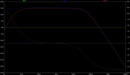
Let's look at the dispersion patterns of the two example horns. The small one is on the left, the large horn is on the right. The top row is dispersion at 35 hz (near the bottom of the passband), the bottom row is dispersion at 100 hz (top of the passband).

An externally hosted image should be here but it was not working when we last tested it.


So clearly the small horn is too small to have much effect on directivity even at the top of the passband. The large horn has a small amount of influence over directivity even at the bottom of the passband, and a huge impact at the top of the passband. What goes for tweeters goes for subwoofers too, the difference is frequency vs size, and undersized horns can't control dispersion.

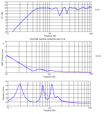
The "impedance transformer" (cone to air) is one of those old sayings that gets passed on all the time but it's not really true at all for small horns. Let's look at the impedance curve of the two example horns. Small on left, large on right.

An externally hosted image should be here but it was not working when we last tested it.


The small horn has an impedance curve that looks a lot like a transmission line, which we know is not considered an impedance transformer. The large horn's impedance curve is much different. The spikes are damped, the dips are not as deep and the average level in the passband is higher.

In the small horn there are narrow bands of very high efficiency corresponding to the huge impedance spikes and in between the spikes the efficiency is very low. The large horn has a higher level of efficiency across the entire passband due to it's sheer size and a much more calm impedance curve. This is what they mean by impedance matching and it doesn't apply to small horns. The impedance curve is where you see it but that's not really what they are talking about either. What they mean is that the impedance curve, the frequency response and everything else is smooth, not spiky so the cone is able to "see" a more constant radiation resistance in the air load at all frequencies in the passband.

Here's actual efficiency. Small horn on left, large on right, 120 liter ported box tuned to about 32 hz on bottom. The small horn does have a lot more efficiency than the much smaller ported box at most frequencies, that's to be expected based on size and having so many impedance peaks inside the passband. The large horn efficiency is much higher than both.

Clearly efficiency spikes at the same frequencies the impedance peaks are at. So if you line up a bunch of impedance peaks inside the passband you can have boosted efficiency for as much as a 3 octave passband. And the larger the enclosure, the more acoustic gain, the more efficiency.

An externally hosted image should be here but it was not working when we last tested it.


Some people might not be aware of what the ported box is actually doing. The front wave is out of phase with the back across a lot of the passband so they are actually fighting each other. At some frequencies the direct radiator output wins and at others the box resonances win. It's a complex summation. This is the direct radiator output (left), the port output (right) and the summed response (bottom).

An externally hosted image should be here but it was not working when we last tested it.


For people that only use WinISD or similar helmholtz type simulators it may not be clear that ported boxes have a series of resonances like a horn. But when you look at port output alone in a picture like that directly above it becomes clear that ported boxes have ALL KINDS of resonances. The people who are aware that there are ported box resonances usually just ignore them, thinking they will be too far above the passband to matter.

But when you look at the port output image it becomes clear that ported boxes and horns are not really all that different. The horn actively uses it's shape to line all those resonances up into a pretty row and give them the individual acoustic gain that they need to provide a propped up flat(ish) response over as much as 3 octaves. The ported box has the same type of resonances but they are at erratic frequencies where they can't help but can only cause trouble. Therefore the resonances need to be pushed up way out of the passband or stuffing must be applied to calm them down. MLTL and the various different types of TL are ported box variants that attempt to make use of ported box resonances instead of ignoring them or stuffing the life out of them. Some types of TL are remarkably similar to undersized horns.

The resonant enclosure types are not that different, they all lie on a continuum based on shape and layout. They all have a series of resonances. How they deal with these resonances might be different but they all have them.

And since that post hinted at but didn't include a picture of frequency response or excursion characteristics of a full size vs undersized horn, here's a random example showing the much flatter frequency response and excursion curve of a full size horn.

Full size on top, undersized on bottom. Both shown with equal input voltage.
The full size horn is about 4500 liters, the small horn is about 370 liters.
Both horns have approximately 2:1 compression ratio.

An externally hosted image should be here but it was not working when we last tested it.


Let's go a step further and look at cone pressure and reactance annulling. These are the same horns shown in the last pic, shown with the same (equal) voltage applied.

Top row is the undersized horn, bottom row is the full size horn.
Left column is pressure on the horn side, right column is pressure on the sealed rear chamber side.

An externally hosted image should be here but it was not working when we last tested it.


Notice two things in that image - first the smaller horn has much higher pressure on the horn side than the much larger full size horn all across the entire bandwidth. (The first big spike in pressure won't matter so much if the horn is high passed, but the higher pressure through the rest of the passband will still apply.)

Second, the pressures on both sides of the full size horn are fairly well balanced (peaking at similar values of pressure) whereas the pressures on either side of the undersized horn cone are at dramatically different pressure. We'll see what this means in the next image.

This is total pressure on the cone - the actual normalized pressure the cone experiences when considering pressure from both sides (not just either side separately as shown above).

An externally hosted image should be here but it was not working when we last tested it.


Notice the same two things in this picture. First, the large full size horn experiences dramatically less cone pressure and stress across the entire bandwidth despite putting out dramatically higher spl.

Second, notice that the pressure peaks are fairly well balanced (peaking at the similar pressures) across the whole passband, and even below the passband. On the other hand, the undersized horn has very little pressure at frequencies below tuning and very high pressures at the peaks above tuning.

This is reactance annulling at work in the large horn and not so much in the small horn. When the pressure peaks below and above tuning are balanced you have good reactance annulling.

Note that the pressure peaks above and below tuning are not exactly the same in the full size horn but they are close. They could have been closer if this was an ideal horn for this driver, but an ideal horn for this driver would have an insanely high compression ratio so compromises must be made resulting in less than perfect reactance annulling.
  • Like
Reactions: deanznz

Talharpa build, something very different!

Here is a Swedish/Estonian Talharpa- bowed harp/lyre sort of thing. You play it like a violin, but fret the strings with your fingers directly. Similar instruments are found throughout Europe,with the Finnish Jouhikko being considered to be more or less the same thing. You also hear the term Strakharpa on occasion. 2, 3, and 4 string versions are found depending on where and who constructed it.

This is tuned CGcg, the first two string are an octave higher than the next pair, and function primarily as drone strings. Generally you only use the first and or second string as melody strings when playing notes... the instrument faces away from you and you hold the frame with your left hand, while resting it on your lap in an upright position.

This one is made out of purpleheart (my favorite wood!) for the frame, back, and tuning pegs, with a western red cedar soundboard, and cherry bridge. Twisted nylon fishing line is used for the strings, but traditionally horsehair or gut would have been used. It measures about 21" tall, 2 1'4" deep, and just under 6" wide.

I can't play it all that well yet, but the little tunes I can do on it have great tone. lots of sustain with this instrument. Good for repeating tunes in folk music. You can hear it in some of the stuff produced by the band Skald, Wardruna, A Tergo Lupi, and there are a handful of artists specialising in them as well.

Attachments

  • IMG_20210325_042807627.jpg
    IMG_20210325_042807627.jpg
    421.9 KB · Views: 412
  • IMG_20210325_042905555.jpg
    IMG_20210325_042905555.jpg
    330.5 KB · Views: 253
  • IMG_20210325_042834383.jpg
    IMG_20210325_042834383.jpg
    688.8 KB · Views: 175
  • IMG_20210325_042823053.jpg
    IMG_20210325_042823053.jpg
    764.1 KB · Views: 172
  • IMG_20210325_042842729.jpg
    IMG_20210325_042842729.jpg
    784 KB · Views: 171

Burson v5i

Head to head with AD797 there was a readily apparent difference when these took their place in the diy phono stage.
Bass is more robust, faster, and has a felt presence. Imaging is pinpoint, very easy to pick out who sits where.

There is no background noise in the deadwax.

Pressings used were Sheffield Labs.

This is better than rolling tubes. Thanks Carlos. Icing on the cake.

Audiomaster - what have i got?

I'm looking for some help from the experts.

I received Audiomaster speakers for my 21st Birthday in 1981. They still sound great!

I retained the usage leaflet but the receipt which confirmed the model number is long gone.

I think they are MSL 2, but would like to know.

They weigh 10.7 kg each and measure 50cm high, 25 wide and 26.5 deep. Hopefully this and the pictures will help

Attachments

  • 20210328_163419.jpg
    20210328_163419.jpg
    224.1 KB · Views: 248
  • 20210328_163446.jpg
    20210328_163446.jpg
    943.5 KB · Views: 191
  • 20210328_163334.jpg
    20210328_163334.jpg
    228.3 KB · Views: 184

Need Help by e80cc tube premp

Hello on all tube experts.Just finished tube preamp with E80CC tube ,but now I have the problem,that the output signal is verry,verry low and when I turn the 100Kohm stepped shunt attenuator till the end the signal is totaly distorted and only about 0.5Vrms.I have checked all the voltages and is all OK,i have put some other e80cc tube in and the same problem,I have put the ecc82 tube in and the same problem,I have disconect the attenuator and put the signal direct from my CD player on tube and the same problem,so now I have no more idea what there could be wrong.This is the shematic,the psu is CLCRC and the tube rectifier is 5852 tube,the anode supply is 250V dc,and the heater is DC 12,6V.
Plese if someone have some idea what could be wrong???😕
In the shematic is 12ay7 tube,I use one piece e80cc per chanel!!

Attachments

  • M77.png
    M77.png
    27.4 KB · Views: 677

Lundahl Chokes and Transformers - Great for SE 6c33c or 300b Project

Hi All

I have some Lundahl items up for grabs. Shipping is from Switzerland, which is sadly a bit expensive for heavy items.

Anyway, if you have some interest in these, send me a message and we can discuss price and shipping options.

2x Lundahl LL1638 / 8H Used but it nice condition. Rated up to 200mA for 8Hy, and 400mA for 2Hy. *SOLD*

2x Lundahl LL1627 /185mA These Single Ended Output Transformers are used but In very nice condition. These work well with 6c33c at around 250V on the plate and bias at -90V. I can show you the load lines and discuss some topologies if you want. Superb sound but these days I don't need quite so much power. *SOLD*


2x Lundahl LL1669A These Mains Transformers are also used but in excellent condition. I doubled up (in parallel) the 6.6V heater windings to heat the 6c33c, and still had two 6.6V windings left for input/driver stage and damper diode rectification. They also have a very handy winding for fixed bias. *SOLD*


All this stuff makes a fantastic SE amp with 6c33c. Of course these items could also be used for SE 300b or SE EL34, KT88, etc... Feel free to reach out to me if you have any questions.

Best regards
Ian

DIY hybrid headphone amp design issues

Hi all,

my first post here, looking for some help and ideas 🙂

So, I want to design a new headphone amp for myself and wanted to mix tubes with mosfets.

My goals are:
- class A headphone amp
- single ended if possible
- drive 32..250ohm headphones
- use at least one tube
- compact design (no big trafos)
- decent sound quality
- low noise

After some tinkering and learning, came up with the following desing mixing ECC83 and IRF530.

attachment.php


According to LTspice, it should work, I haven't built a prototype yet. The output THD is around 0.7%, gain around 14dB flat in acoustic range (20Hz..25kHz).

It's my first real tube amp that I want to design right, so there are a few questions perhaps someone here can help answering.

1. ECC83 operating parameters, I've been looking at various circuit schemats and values of the anode/cathode resistors tend to be bigger. I'm thinking whether the values I used are correct in reality and whether the current flowing through the tube won't be too big to handle.

2. The R1 resitstor acting as mosfet load is just 27ohm. I couldnt increase it without introducing distortion especially with 32ohm headphones. It should work but considering the voltage and the current the power loss will be huge and it will get really hot. Is there a way around this? I've seen some "constant current supply" circuits but not sure how could I use it here.

3. I've tried to reduce THD level by adding some feedback look, the R13 is the attempt to do so, with it I get around 0.7% THD, without around 1.1%. Does it make any sense there?

Attached the LTspice file if anyone interested with playing with this design.

Attachments

  • HybridAmp2.asc
    HybridAmp2.asc
    3.9 KB · Views: 69
  • hybridamp2.JPG
    hybridamp2.JPG
    68.5 KB · Views: 941
  • hybridamp2_2.JPG
    hybridamp2_2.JPG
    63.7 KB · Views: 270

Surprising amounts of rectifier intermodulation

This is an instrument amp, but the topic I think is relevant here in 'tube section' as well...?

To be clear, this amp sound absolutely amazing. I actually believe it has something to do with the NOS late '60s carbon comps - but lets not go there...sorry.

The point here is I am a little surprised at the amount of rectifier (100Hz+) intermodulations. Look at the 1kHz test signal and the harmonics around it, they are 100Hz apart. The first +-100Hz are only -40dB down.

This is at max clean power just below clipping. With 6AX5GT rectifier this is ca 12watts and with solid state it is ca 18watts.

I think I have the layout and routing ok. The power supply is at one end, the first cap is really close to the rectifiers. The b+ wire (red) is routed close as possible to the GND copper bus. The loops should be farely small and tight.

I have seen this when the magnetics (power supply) is close to the OPT or IT, but here I was expecting a little better.

Any comments?

Is this just normal?

Attachments

  • amp.jpg
    amp.jpg
    311.1 KB · Views: 256
  • 17ohm_max_gridplatefft_ss.png
    17ohm_max_gridplatefft_ss.png
    66.2 KB · Views: 261
  • 17ohm_max_tuberect.png
    17ohm_max_tuberect.png
    68.8 KB · Views: 262
  • internal.jpg
    internal.jpg
    132.3 KB · Views: 271
  • external.png
    external.png
    602.5 KB · Views: 260

RIM Stereomaster

I have come across this old German amp on an auction site, a RIM Stereomaster, and there was a schematic with the listing which has stretched my understanding of tube circuits.

The amplifier is EL84 single ended output, with an EF804 driver and ECC83 input stage + tone controls. However I am finding it hard to understand the output stage.

There is negative feedback from the 4ohm tap on the output transformer.

The EL84 is DC coupled to the EF804. The EF804 has a capacitor to ground and some potential divider arrangement on its load resistor. The screen of the EF804 is coupled to the cathode of the EL84.

It is not completely obvious how the EF804 is getting its input, or how the feedback circuits work together.

Would be very interesting if someone could explain how the driver is functioning.

Attachments

  • RIM Stereomaster.jpg
    RIM Stereomaster.jpg
    544.7 KB · Views: 170
  • RIM Stereomaster cover.jpg
    RIM Stereomaster cover.jpg
    278.8 KB · Views: 169

24" hartley photos -

two nonidentical pair -

An externally hosted image should be here but it was not working when we last tested it.


An externally hosted image should be here but it was not working when we last tested it.


An externally hosted image should be here but it was not working when we last tested it.


An externally hosted image should be here but it was not working when we last tested it.


An externally hosted image should be here but it was not working when we last tested it.


`````````````````````````````````````````````````


An externally hosted image should be here but it was not working when we last tested it.


An externally hosted image should be here but it was not working when we last tested it.


An externally hosted image should be here but it was not working when we last tested it.


An externally hosted image should be here but it was not working when we last tested it.


An externally hosted image should be here but it was not working when we last tested it.


An externally hosted image should be here but it was not working when we last tested it.


An externally hosted image should be here but it was not working when we last tested it.

Where does Signal Ground come from? LM3886

Hi this is my first post.

I'm tinkering with an LM3886 circuit that I'm building in my spare time, mostly following the design from a website and partially following the reference diagram from the datasheet.

One thing that's confusing me 😕 is where does the Signal Ground come from?

Does the Signal Ground come from the amp PSU or from the equipment that is providing the audio source waveform (iPod, phone, computer etc)?

The website I'm following as the basis of my build has it coming from the amp PSU.

If it's really supposed to be from the amp PSU, how does the circuit complete itself (conventional current flow) with respects to the audio source equipment, if there doesn't appear to be a path back to the computer? (current flows from the computer into pin 10 of the LM3886 and then flows out via Signal Ground on the amp back into the house wiring?)

Thanks

Attachments

  • index.png
    index.png
    15.8 KB · Views: 450

Blaupunkt BPA 2120B

This is pretty different for me. This amp has like 6x separate small and large circuit boards in it, all single sided. I took a close look under a magnifier glass but could not find any solder issues to speak of.

I cannot get this amp to power up.

There are 2x30A fuses, and each fuse runs to two separate PS's which are running separate 494 PWM ICs on the same PCB. Each PS seems to have its own fuse. I can tell one of the fuses is drawing only 0.1A of power as when I pull that fuse the amp drops to 0A pull. The other fuse doesn't do anything.

The power LED lights up. Thats about all I get?

First 494:
1: 0.001
2: 2.440
3: 0.090
4: 4.93
5: 1.612
6: 3.782
7: 0.01
8: 4.97
9: 0
10: 0
11: 4.96
12: 14.02
13: 5
14: 5
15: 5
16: 0

Second 494
The only difference is pin 6: 5.04v. Everything else is same as first 494.

active blend pot, bass guitar

Finally I tested through the active EQ. But, I dont like how the blend pot works:
blend_pot.png
At the mid position, the blend sound is very prominent (and I like it most).
But as soon as I turn left/right, there is a very little room for smooth transition between pickups.
The tone abruptly changes towards one of the pups.

I think of buffering the pickups:
But I don't know how the circuit would handle short to ground (end positions of blend pot).

Buffering would handle the pot load and bring back some trebble.
Up til now, I was testing the pickups with no pot load - connected to amp directly.
The blend pot load seems to be 250k || 250k ~125k

Attachments

  • blend_pot.png
    blend_pot.png
    12.9 KB · Views: 194
  • buff4.gif
    buff4.gif
    1.4 KB · Views: 165

Help Needed with TSE-II Configuration Decisions for a First Time Tube Builder

I am building my first tube amp and would really appreciate help from experienced builders to select the right configuration and parts for a good outcome on my TSE-II build.

Background Information

Before I jump into the build decisions, I wanted to provide some details on my system, musical tastes, and goals for the amp.

My primary speakers are Wooden Designs Vulcans (FE206EN Back Horn ~ 96 db efficency) they make good bass and I would like to run them full range with this amp. In another thread there was a comment that the impedance of these speakers might be a problem for a tube amp. I have included a simulated impedance chart below taken from this thread. Does the impedance look ok?

I mostly listen to classical/acoustic music and classic rock, at moderate volumes (usually at night when the kids are in bed).

I have two goals for this amp 1) to get an accurate feeling for what a very good tube amp sounds like 2) make the amp versatile enough to run both high efficency drivers and some thing more conventional along the lines of Lynn Olsen's Ariel speakers.

If I am really missing the boat on my build decisions, please keep in mind that I have never heard any tube amplifier before, and never even held a vacuum tube until my 5842's arrived a couple days ago.

Build Decisions:

Tubes: 300B's - Available New, Most Power (helps with the versatility goal), Good Reputation, thinking Genalex Gold Lion from Viva Tubes (~$210 per pair)

Output Transformer - 5000 ohm primary, Multitap 8 ohm and 4ohm. Based on the Western Electric table of "Recommended Operating Conditions" for the 300B i am thinking that a 5000 ohm primary operating around 400V and 60 mA would be a good balance of power vs. distortion. Thinking the One Electron UBT-2 would be a good choice, but I am definitely open to something else.

Built in Volume Control - I would like to include a built in volume control and source selector, but I don't know the gain of this amp. Any idea on the gain of a 300B TSE-II?

Thanks!

Attachments

  • Vulcan Curves.png
    Vulcan Curves.png
    35.5 KB · Views: 794

Repair problem NAD 325BEE

I don't know how I did it but I have snapped the plastic base that holds the speaker output terminals.
Pix attached
Looking at the exploded parts list in the service manual it seems that this assembly isn't an available spare part
I'd like some beginners advice on how best to proceed
If I can't do the work I know of somebody competent who can and who charges fairly

Attachments

  • IMG_1821.JPG
    IMG_1821.JPG
    131.6 KB · Views: 87
  • IMG_1820.JPG
    IMG_1820.JPG
    117.2 KB · Views: 90

Bamf5500 in Protection

Hi,

The amplifier turns on correctly and there is audio on the output. but without load increasing the volume increases the input current from 1 to 4 amps. sometimes it goes into protection.
No shorted or leaky mosfets at source like output stage, all transistors on sub pcb board were replaced. I have noticed that when using an exact 12v source, the voltage on the secondary of the source is 63V symmetrical. Connected in the car to 13.5v the voltage in the secondary changes to 71v symmetrical. with 13.5v the transistors on the sub pcb (MOSFET driver) get too hot (Q111, Q116 and Q118). the switching frequency on the source mosfets remains constant with both input voltages.
The source controller is an IC SG3525AP. I don't know if that behavior in the source is correct.
The schematic

any suggestions?

Note: the diagram corresponds to the mosfet controller, sorry if I made a mistake when passing it.

Attachments

  • IMG_20210318_222756.jpg
    IMG_20210318_222756.jpg
    421.1 KB · Views: 58

DSP for 3e audio amp

Hi all,
I recently purchased a completed class D amp with DSP from 3e audio. I want to use the DSP but have no experience (total newbie except for a Bottllehead amp kit and Fostex 208 speaker build years ago). As far as I know, I have to buy this:
freeUSBi - complete kit | Audio and signal processing | even elements Shop

I have to open the amp and plug a cable into the box. That's about as much as I know.

Unfortunately this seems to be sold out everywhere. Any help would be greatly appreciated. Thanks
Ade

FS: B & C 10NW64-8

B & C 10NW64-8 10” Neodymium Woofer


One each - I used this in a very elaborate folded horn sub enclosure a few years back. I never got the project properly dialed in so it sat in the back room for a few years then I eventually took the sawsall to the box and this is what remained.
It probably has less than 30 hrs on it. Rumor has it that it’s an amazing driver and especially shines in instrument amps.


B&C 10NW64 10" Neodymium Woofer


$85 plus shipping – Continental US Only

Attachments

  • IMG_0930.jpg
    IMG_0930.jpg
    923.9 KB · Views: 138
  • IMG_0931.jpg
    IMG_0931.jpg
    497.4 KB · Views: 114

Electret Condenser Headphone (AT-706) loss of volume

Exec Summary: Can Electret Condenser headphones really lose their charge and degrade in terms of SPL, or is this more likely a XFMR issue?

I'm researching an issue with my old Audio Technica AT-706 headphones. These are electret condenser (no bias supply) that I just pulled out of a box in my basement that they had been in for some 20+ years. I thought I had remembered that one channel was gone and at the time had suspected the transformer unit, and I just managed to buy a new/used one from eBay. Well I plugged them into that new/used transformer unit and they did work but weren't very loud. I then went back to my old xfmr unit and that seemed to work too on both channels (so not sure what had originally been wrong with the unit!). However, the volume is low with both xfmr adapters, so I suspect there is another issue. I am using a Yamaha receiver rated for 50W and have to crank it up to full volume to get a mid-level volume on the headphones. Does this likely mean the headphones have lost part of their permanent charge? I saw some comments on a thread about this happening and then others saying this is not the case. Is there any way to "re-charge" them?!
Thx

Tube preamp with loudness compensation

My girlfriend has a very high quiet squeaky voice that is hard to hear. And she talks a lot. My system at her place sounds like crap at the low volumes required to have a conversation, but totally awesome at 100db+. Wondering if there is a decent tube line stage circuit including loudness compensation? Loudness and tone controls seem to be the antithesis of decent audio, but my system only sounds good at one volume without it. Ideas or suggestions? Headphones are out, I would never get any again....

Greetings from Maritime Canada

Super quick intro post. I've lurked in bursts when the mood struck for audio knowledge and information. Built some stuff in high school with friends (general electronic projects) and briefly in uni as an engineering major before math won (hence my respect/admiration for Fourier).

My audio listening is digital source to headphones (via a small SMSL integrated DAC/HPA), but recently my situation has changed where I'm able to explore speaker listening. A few online reviews (Steve Guttenberg in particular) raved about the amp camp so much I pulled the trigger on one yesterday. I can't wait to break out the soldering station and start building! I also want to build the ACP+ (I binge read from about post 661 onward- checking R4 is burned into my brain lol) but I am waiting for parts to come back in stock at the diyaudiostore so I can buy everything at once. Regardless, I cant wait for my amp camp kit to arrive so I can start building. A friend of mine was kind enough to ship me a set of Klipsch bookshelf speakers to start my foray into speaker listening so I'm pretty excited.

In a parallel branch, I'm also exploring what the fuss over DSD is about, so I downloaded a few free (as in no charge) samples in DSD64 to ensure I can get foobar working. Maybe in the near future I'll get a DAC with DSD support to take advantage of the eventual ACP+ that will sit on my desk.

Oh I also want to get some of those sweet VFETs Mr. Pass mentioned in a "get em while you can" thread, but my money tree died and I haven't been able to resurrect it. Tough choices had to be made and the ACA won over VFETs. Hopefully the decision is not regretted.

That's about it for now. Have a good one!

Power supply low noise resistors

Hi
I have an amplifier mark levinson 33h which uses RN65 resistors in it's power supply.
Since the pcb became black colored shows that those resistors gets hot !!
So my question is do you think it's wise to replace the RN65 by GS-3 resistor? I didn't seen it's low noise in it's pdf data sheet
But the RN65 vishay comment it's low noise-40db
What do you think ???

Another NAD 319 problem.

I have a NAD 319 that is misbehaving on the left channel.
As per other threads this amp is in protect mode as soon as you switch on. The owner claims this happened since plugging in a headphone cable. I'm not so convinced. Headphone sound is fine though (especially as it's a separate circuit)
I have the service manual and have been going through the voltages and I have:

  • +/- 60V rails to both left and right amplifiers (measured on the collectors of the output transistors)
  • +/- 67V rails to both left and right amplifiers
  • Left channel measures -6V on the output (Right amp measures 0V)
  • 0V DC measured at the input of both amp boards
I think the fault lies within the driver stage of the amp but not sure where to look. Any ideas? Any more information needed? (I can upload an annotated schematic of the left channel if this would help)


Thanks in advance

Strange op amp problem.

I have designed a transistor matcher which is basically just an inverting transistor stage.
The DUT base is driven from an TL084 through a 1 k resistor.
I chose the 1k so as not to load the op amp output.
The DUT npn base is driven fine through the 1K resistor with a nice clean collector waveform.
However, the DUT pnp gets quite a bit of oscillation when pnp transistor gets turned on. The oscillation is at the op amp output too which is strange.
The only difference is npn is driven from +ve supply and pnp driven from -ve supply.
I can tune out the oscillation by replacing 1k with 3k3 but anything less than 3k3 results in oscillation.

TDL RTL2 upgrades

Hi!

I won a pair of RTL2 on ebay for £5.50!

Decided to modify and upgrade them and need some help/advice please....

First step: Crossover, whats the best way to impove it?

Second step: Drivers. Ive been advised to go for Vifa M17WH-09-08 midbass and Morel MDT30s tweeters. Are there any alternatives which would work without altering the crossover?

Third step: Enclosure. I plan on lining every internal surface with self-adheisive Bitumen deadsheet. Im also keen to learn of any other materials I could use for damping. What about 'dimple foam' or 'acetate fibre'?
Finally im going to attatch a new front baffe over the existing one (click attatchment) and apply 'Birdseye maple' veneer....

Any advice, hints, or tips will be greatly appreciated!

Attachments

Help with ground hum/buzz - DIY amplifier

Hello diyaudio forum members - I am currently struggling to fix a ground loop/buzz in my DIY TPA3255 amplifier build. The amplifier board is drMordor's Akita "AllInOne."

It's an intermittent problem. I will do my best to succinctly describe the build and issues:

Amplifier and chassis details:

  • RCA inputs are insulated from the metal chassis
  • Alps potentiometer is grounded to the metal chassis
  • RCA shield is tied to the ground pins on the potentiometer
  • A safety ground is connected to the metal chassis near the IEC connector
  • The PCB's ground plane does NOT connect with the mounting hole pads

System details:

  • MiniDSP 2x4HD with 2x RCA going to amplifier and 2x RCA to active subwoofer
  • Amplifier and MiniDSP are connected to a single power strip
  • Outlet is NOT grounded - ground lift used

Problems experienced:

When I initially plugged everything up, the system worked perfectly with zero noise or hum.

To experiment with subwoofer placement, I unplugged the power to the sub and immediately got a very loud buzz in the main speakers.

I removed the subwoofer and any extraneous peripherals (TV, mini PC) from the power strip. Still got the buzz.

I plugged the amplifier into a grounded outlet via an extension cord - no luck.

Then I experimented with temporarily removing the safety ground from the chassis and separating the volume pot from the chassis to no avail.

I can get the system to work when the subwoofer is connected - as if the amplifier is "grounding" itself to the subwoofer - but then I discovered that I can make the system revert to the buzzing noise by flipping light switches elsewhere in the house (or the bathroom fan, for example).

I have done a fair amount of reading and have determined that I have a ground loop of some kind, but I'm unsure of how to proceed. Ideally, I believe the RCA ground would stay floated all the way until the amplifier, but it is being connected to the chassis at the volume potentiometer.


I would greatly appreciate any guidance or suggestions for next steps. Thank you!

Attachments

  • IMG_20210329_132051.jpg
    IMG_20210329_132051.jpg
    333.6 KB · Views: 349
  • IMG_20210329_132105.jpg
    IMG_20210329_132105.jpg
    389.3 KB · Views: 321
  • IMG_20210329_132115.jpg
    IMG_20210329_132115.jpg
    904 KB · Views: 274
  • IMG_20210329_132151.jpg
    IMG_20210329_132151.jpg
    913.1 KB · Views: 307
Projects by fanatics, for fanatics
Get answers and advice for everyone wanting to learn the art of audio.
Join the Community
507,795
Members
7,888,764
Messages

Filter

Forum Statistics

Threads
406,259
Messages
7,888,764
Members
507,795
Latest member
piotechnec