Hi all,
my first post here, looking for some help and ideas 🙂
So, I want to design a new headphone amp for myself and wanted to mix tubes with mosfets.
My goals are:
- class A headphone amp
- single ended if possible
- drive 32..250ohm headphones
- use at least one tube
- compact design (no big trafos)
- decent sound quality
- low noise
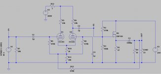
After some tinkering and learning, came up with the following desing mixing ECC83 and IRF530.

According to LTspice, it should work, I haven't built a prototype yet. The output THD is around 0.7%, gain around 14dB flat in acoustic range (20Hz..25kHz).
It's my first real tube amp that I want to design right, so there are a few questions perhaps someone here can help answering.
1. ECC83 operating parameters, I've been looking at various circuit schemats and values of the anode/cathode resistors tend to be bigger. I'm thinking whether the values I used are correct in reality and whether the current flowing through the tube won't be too big to handle.
2. The R1 resitstor acting as mosfet load is just 27ohm. I couldnt increase it without introducing distortion especially with 32ohm headphones. It should work but considering the voltage and the current the power loss will be huge and it will get really hot. Is there a way around this? I've seen some "constant current supply" circuits but not sure how could I use it here.
3. I've tried to reduce THD level by adding some feedback look, the R13 is the attempt to do so, with it I get around 0.7% THD, without around 1.1%. Does it make any sense there?
Attached the LTspice file if anyone interested with playing with this design.
my first post here, looking for some help and ideas 🙂
So, I want to design a new headphone amp for myself and wanted to mix tubes with mosfets.
My goals are:
- class A headphone amp
- single ended if possible
- drive 32..250ohm headphones
- use at least one tube
- compact design (no big trafos)
- decent sound quality
- low noise
After some tinkering and learning, came up with the following desing mixing ECC83 and IRF530.
According to LTspice, it should work, I haven't built a prototype yet. The output THD is around 0.7%, gain around 14dB flat in acoustic range (20Hz..25kHz).
It's my first real tube amp that I want to design right, so there are a few questions perhaps someone here can help answering.
1. ECC83 operating parameters, I've been looking at various circuit schemats and values of the anode/cathode resistors tend to be bigger. I'm thinking whether the values I used are correct in reality and whether the current flowing through the tube won't be too big to handle.
2. The R1 resitstor acting as mosfet load is just 27ohm. I couldnt increase it without introducing distortion especially with 32ohm headphones. It should work but considering the voltage and the current the power loss will be huge and it will get really hot. Is there a way around this? I've seen some "constant current supply" circuits but not sure how could I use it here.
3. I've tried to reduce THD level by adding some feedback look, the R13 is the attempt to do so, with it I get around 0.7% THD, without around 1.1%. Does it make any sense there?
Attached the LTspice file if anyone interested with playing with this design.
Attachments
> output THD is around 0.7%
At what level?? 0.5V? 5V???
It seems extreme to waste near 20 Watts of heat to put milliWatts in headphones.
R13 is sure not NFB. I do not know why THD changes, maybe someone can explain that.
At what level?? 0.5V? 5V???
It seems extreme to waste near 20 Watts of heat to put milliWatts in headphones.
R13 is sure not NFB. I do not know why THD changes, maybe someone can explain that.
You may want an ESD diode on the MOSFET gate.
You could run the output line back, something like this:

You could also look at hooking noise rejection back into it too.
Lastly what are you using for the 200V and 24V SMPS/Linear?
Careful of having one power supply forming the bias of the grid into another powered stage - ie if you feed back from the 24V into the 200V, you could be running with a positive grid, so think a little on amp startup. Same goes with input grid bias on startup. You may find the valve starts conducting at full current.
You could use a +24 bias on the front end cathodes (giving a -24V grid - assuming that works for that valve) then release when it's all ready.
You could run the output line back, something like this:
You could also look at hooking noise rejection back into it too.
Lastly what are you using for the 200V and 24V SMPS/Linear?
Careful of having one power supply forming the bias of the grid into another powered stage - ie if you feed back from the 24V into the 200V, you could be running with a positive grid, so think a little on amp startup. Same goes with input grid bias on startup. You may find the valve starts conducting at full current.
You could use a +24 bias on the front end cathodes (giving a -24V grid - assuming that works for that valve) then release when it's all ready.
Thanks for replies.
I've spent some time on improving the circuit, built the previous one on a breadcrumb, refined and finally came up with this:

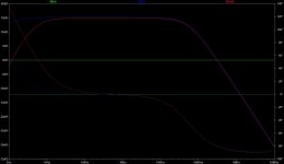
Mosfet is driven by a separate differential amp and added a constant current source to reduce the load. Also changed the overall design of the output stage to symmetric voltage to get rid of the large caps. The frequency response is even flatter than before in the whole acoustic range (20Hz ... 25kHz)
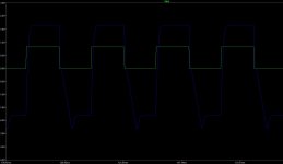
Now, THD has reducec which is good, both while testing for 1kHz and 10kHz and I think the output stage looks allright. That being said Im slightly concerned about the differential tube amp in the input stage. I've tested the circuit with a square wave and while the output is not adding much of a distortion the input with the tubes does some especially on high frequencies, see the screenshot. Is that kind of distortion somethign to be worried about? the square wave is 10kHz with 50us rise and fall times.

I've spent some time on improving the circuit, built the previous one on a breadcrumb, refined and finally came up with this:
Mosfet is driven by a separate differential amp and added a constant current source to reduce the load. Also changed the overall design of the output stage to symmetric voltage to get rid of the large caps. The frequency response is even flatter than before in the whole acoustic range (20Hz ... 25kHz)
Now, THD has reducec which is good, both while testing for 1kHz and 10kHz and I think the output stage looks allright. That being said Im slightly concerned about the differential tube amp in the input stage. I've tested the circuit with a square wave and while the output is not adding much of a distortion the input with the tubes does some especially on high frequencies, see the screenshot. Is that kind of distortion somethign to be worried about? the square wave is 10kHz with 50us rise and fall times.
Attachments

Now you've started changing the design 😉 The front pair could be made a differential amp.. then drive the output differential amp. I take it you're not using global feedback?
Next up is what power supply..
With LTspice I would look at non-ideal models, and put some ESR on the caps too.
Next up is what power supply..
With LTspice I would look at non-ideal models, and put some ESR on the caps too.
Last edited:
Nope, not yet at least, but I'm still playing with this design to maybe will get there eventually. I have a slight view how to get a global NFL here but I guess will need a another capacitor to adjust voltage difference between the input and output stages.Now you've started changing the design 😉 The front pair could be made a differential amp.. then drive the output differential amp. I take it you're not using global feedback?
That one's easy, I have a single AC 12V adaptor. The current is rectified with two greatz bridges to get symmetric +12V 0 -12V, and stabilized with 7812 and 7912 with large caps near mosfets to provide energy contingency.Next up is what power supply..
Tubes are powered by a small reversed transformer 250-12V next rectified and filtered in a RC filter. Gives around 150V under the load of two physical ECC83 lamps in this design.
- Home
- Amplifiers
- Headphone Systems
- DIY hybrid headphone amp design issues