TDA2050/LM1875 Project - Oscillation issues

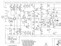
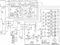
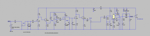
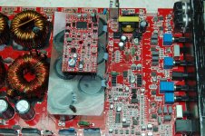
Hello all! After building valve amps over the years I decided to delve into solid state and rebuild an old project of mine. It was an amp I built back when I barely knew ohms law! It was to have a standard TDA2050 PA with a simple preamp that had good tone controls. No distortion, just a nice clean flexible amplifier.

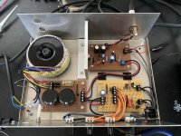
I built the PSU and PA boards, they worked perfectly. I breadboarded the preamp and that too worked nicely (although very noisy, but it was on a breadboard!). I then built the preamp board and assembled the amplifier.

On first switch on it would oscillate all the time, no matter what I did. The oscillation seemed to be in the preamp but I couldn’t pin it down, it seemed to be everywhere, I could even see it on the scope when probing the ground points! (Which all measured 0.1Ohms or less). I moved the volume control ground to the PA board and the issue was solved, except it would sometimes return if I turned up the volume past 7 and this is without any signal on the input.

Unfortunately whilst trying to solve the oscillation the TDA2050 chip went bad and no longer works. Which I find a bit odd as even though it was oscillating it was only drawing 400mA. I have an LM1875 on order to replace it, but wondered if anyone here had any ideas about the oscillation? The preamp board tests fine by itself and the PA board did. The only change I made between testing and assembly was the feedback on the TDA, I went from 22K/1K to 18K/1K. That’s still 25dB of gain though and within spec for that chip I believe.

Any ideas would be most welcome 🙂
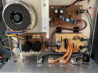
Attachments

  • F60E1738-DD93-4A17-9FEA-D9796BE0A4D1.png
    F60E1738-DD93-4A17-9FEA-D9796BE0A4D1.png
    26.6 KB · Views: 545
  • 7503E264-F2B6-4302-A29E-30491E45C5AC.jpg
    7503E264-F2B6-4302-A29E-30491E45C5AC.jpg
    1 MB · Views: 559
  • A4F1BD5C-8A5C-4F06-98B3-EA202258290D.jpg
    A4F1BD5C-8A5C-4F06-98B3-EA202258290D.jpg
    1,011.3 KB · Views: 651

Philips CD630 CDM4/19 Laser Current Adjustment

Hello All,

Looking at help for laser current adjustment for the Philips CD630 CDM4/19 CD player.

The service manual states to adjust the laser current using potentiometer R3520 and also measure voltage across R3501 for 50mv DC (attached Image 1).
Image 2 is the reference of test points in service manual block diagram.

In the CD630 resistor R3501 is shorted with a piece of wire and I am not sure where to measure the voltage across to get 50mv DC.
Are there other test points which I can use to perform the 50mv DC adjustment ?
Or should I remove the short and replace it with a 4.7k resistor then perform the DC voltage adjustments.

Please let me know your inputs regarding the same.

Thanks in advance for your help and support.

Attachments

  • Image 1.jpg
    Image 1.jpg
    64.7 KB · Views: 345
  • Image 2.jpg
    Image 2.jpg
    97.1 KB · Views: 354

Takechi enclosures for tube amps - Anyone?

Hello forum,

I´m just about planning a 300b SET amp and would realy like to use a Takechi enclosure right now. When ready the amplifier should look like this:

An externally hosted image should be here but it was not working when we last tested it.


Has anyone made experiences with those enclosures and could please tell some things about it? Are there sources in Europe where they can be orderd?

Many thanks
Rene

SE Amp with Thoriated Tungsten output tube

Dear All,

I use a 300B SE DIY amp for long time. I wish to build this amp within some limitations viz

1. Low cost
2. Outout transformer should be 3k or 5k
3. B+ 400volt max
4. Class A1 only (no grid current)
5. Triode or shade feedback output

3 watt output is good for me. I thought 865, Hy69, 2E25 (triode connected) might be good candidates. But I find little info about them. Please help to realize my long time dream come true. I will be most obliged to you.

Regards

The "Force 8" collaborative design

The “Force 8” speaker design project

I’m starting this thread as a design exercise – a virtual design, aka a thought experiment. I’ve been thinking about it for some time, and I hope that it reaches fruition in a physical DIY design. Should it make it that far, then it will be my wish that the plans and specs will be shared amongst the audio DIY community.

What is the “Force 8” project? Well, the Beaufort wind scale describes a force 8 as a “fresh gale”. My aim is to create a modern 3-way design, paying visual and performance homage to the Gale GS401a. (Hifi enthusiasts of a certain age may now begin to reawaken longings, mentally drool, etc.)
Yes folks, the plan is to design a speaker that visually evokes the silver end-capped “amp-killer” that was the stuff of dreams for many of us.

In any design process there have to be some rules, and so here they are:

THE RULES

1. This is NOT a cloning exercise. The speaker will use new, currently-available drivers, not vintage units or NOS (new old stock).

2. The speaker will maintain the L:W😀 aspect ratio of the original GS401a, and will be sized somewhere from original actual size to 115% of original. (I figure that extra internal volume will permit some extra scope for driver selection, without overly compromising the object of “visual homage”.

3. The design will be a sealed cabinet.

4. The complement of drivers will be the same: two 8” bass drivers, a 4”-ish single mid-range and a single tweeter. (I’ve given thought to using a modern full range paired with a super-tweeter, but that will be a topic for further debate.)

5. For maximum flexibility in driver selection, the speaker will be tri-amped. Similarly, it is my suggestion that a miniDSP be used in preference to a XO. (In the fullness of time it may be that a suitable XO can be developed, but for the moment, we’ll use a miniDSP (or similar). That will facilitate the sharing of different approaches to crossing between driver units.) Drivers of any impedance may be suggested. Bass & midrange should be cones and the treble should be “visually similar” to the original treble unit, & all are to be flush-mounted on the baffle.

6. The speakers will play as low as the original GS401a’s and as high as the original GS401a’s. Watts are now cheap, so the overall sensitivity is perhaps less critical, but let’s agree that the speakers should be aiming to recreate (at the least) the frequency range & SPL that the originals could muster.

7. The arrangement of the drivers on the baffle will maintain (as neas as possible) the original spatial relationship (to maintain the “visual homage”).

8. There will be end caps. I’ve had some thoughts about this feature, and I have a “cunning plan” – but more of that later. The end caps will be a cosmetic feature and may be chromed metal, painted (two-packed?), or wood-grain. My concept is that they should be removable, perhaps upgradeable? (More about this topic later. It is not essential to the driver and cabinet design.)

9. The GS401a’s’ cabinets featured an 18mm proprietary 3-layer material. For simplicity’s sake, I’ll specify void-free 18mm ply. (Please DO NOT chime in to ignite a flame war about MDF, etc.!)

10. The GS401a’s cabinet had an internal brace. The force 8 design will feature two “holey braces” (nod to Planet10), one behind each bass driver.

11. The GS401a’s were designed as stand-mounters. The Force 8’s performance should mirror the placement options of the GS401a.

12. To borrow a term from engine-building I propose that contributors submit ideas and comments in 3 categories:

Phase I – True DIY “frugal-phile”, making the best of drivers and materials of limited cost, to achieve a nevertheless pleasing performance;

Phase II – Where I anticipate most effort will be made, using drivers and components readily available and reasonably priced. Nothing exotic.

Phase III – Cost-no-object. Go hard – exotic drivers, yak belly fluff stuffing (cryogenically-treated, of course), silver wiring, etc. - but don’t expect to have lots of company.

13. The final rule is that I want to make it clear that I don’t want contributions telling me I need to use 6” or 10” woofers, one woofer instead of two, a vented cabinet, or any other fundamental change to the approach. Find your own sandpit. (Any such suggestions will be referred back to this rule.)

I have done a considerable amount of research on the GS401a and I will be posting links to web resources, the Gale Yahoo Group, etc.

I live in Brisbane, Australia (no, not Austria!) and it would be great if some local DIY enthusiasts joined the endeavour – but hey … everyone is welcome. Bring your friends.

cheers

Doug

NAD 7225pe burning resistor, help needed

Hi all

I had a working, but humming, NAD 7225pe before I managed to slip while probing and fry the output resistors on one channel. It was working fine after replacing all the caps apart from the offset on one channel. Anyway, I was always treating this as a learning experience.

I have now built a dim bulb tester and replaced the output transistors, Q409, Q411 and trimpot Q411. On powerup he display lights up but it only takes a few seconds before R437 smokes up and I flick the bulb tester off. The other channel may be ok but I turn it off so quickly it’s impossible to know. I am working through the components one by one on the suspect channel but everything is checking out ok. I did replace Q411 on both channels with KSC2690A-Y transistors which appeared to be a suitable substitute.

I guess as I was looking for some insight as to what could be causing to resistor to burn but also what strategy to take moving forward. I am considering buying a variac and also ways to power up just one channel? I am not entirely sure how to do that from the schematic. Any help appreciated.

Cheers

Attachments

  • PNG image.png
    PNG image.png
    244.9 KB · Views: 162

Dynaudio 17M75 Drivers Pair

<<Reduced>> Pair of Dynaudio 17M75. These drivers are extremely well made and set the standard when they came out. They are in very good condition. the foam dust cover on the rear vent of one driver has deteriorated. It does not affect the driver. The terminals are mint see photos. If you have any questions PM me. Buy in confidence, check out my 100% ebay rating, (jimmbones) . Buy to pay shipping I'll eat Paypal charge. $165 now $150 pair (sold as a pair) See subsequent posts for pics

Question for Fostex builders

I've been looking at some Fostex fullrange datasheets, and one spec. In particular always jumps out to me. Their very low X-Max. Well under 1mm. Even their drivers specifically mentioned by Fostex as designed for bass-reflex application, such as the FF series, seem to have very low X-Max. Markaudio equivalent drivers spec. X-Max of several millimeters. Nearly all of the Fostex DIY speakers which I saw on YouTube are BR. I only saw one back-horn speaker. I'll assume that X-Max hasn't been a problem based on the success of Fostex project builds.

So, my question is, why has this not been a problem in practice? Must Fostex drivers be played at a low loudness? Something must give, so what am I missing?

VU meter in an NCore400?

I have a pair of Hypex NCore 400 mono block kits headed my way. It would be super cool to have an analog VU meter on a custom front face. I would only want to do this if it can be implemented without any degradation to the amp's performance.

As a machinist and woodworker, a custom face plate wouldn't be a problem. I'm also competent with a soldering iron. But an electrical engineer I AM NOT. So in classic forum fashion... "Where do I go, what do I do?"
Thanks, J

POT between EAR834 phono and power amp, buffer?

hi
I build the EAR834 phono base 12ax7 tube.

i want to connected this phono stage to my single ended power amp

i order 20kohm ALPS RK27 for put between the phono and the power amp.

when i plug the POT, the high frequency is disappeared, its because the capacitance of the amp.

I would appreciate for recommendations for simple buffer

Attachments

  • Tube-MM-Phono-Stage-Amplifier-Board-PCBA-Ear834-Circuit-Vinyl-LP-Amp-No-Including-12AX7-Tubes.jpeg
    Tube-MM-Phono-Stage-Amplifier-Board-PCBA-Ear834-Circuit-Vinyl-LP-Amp-No-Including-12AX7-Tubes.jpeg
    147 KB · Views: 111

Crest Audio CA12

Hi

I am working on the above mentioed power amp. It is a class H amp. The problems are:-
1) Channel 1 - There is no sound. The red "Clip", the green "Signal" and the red "Protect" LEDs are permanently ON. The green "Active" LED is OF

2) Channel 2 - When powered ON, the red "Clip" and "Protect" LEDs turn on and after about 2 to 3 secs, both the red LEDs turn off and the green "Active" LED comes on and there is sound. Then after about to 20 to 30 secs, the "Protect" LED starts to flicker and then comes ON steady, after about a sec later, the relays clicks OFF, the "Active" LED turns OFF and the sound goes OFF.
Can someone guide me on what can be the problem or what should I check.

Thanks.

Attachments

A and T labs K6 amplifier

Hi

I wonder if someone made ​​this amplifier? K6 700 Watt Audio Amplifier and Switching Power Supply

I drew pcb for this amplifier. Amp seems interesting but some people say this is a bucket of amplifier. Biggest complaint was that the MPSA06 can not cope with the parasitic capacitance of IRFP transistors. Should I change something on the schematic? Are there any disadvantages? DC servo and protection I had planned to mount parallel to the main plate, I left the 4 holes on the main board for it.

I found the fact that this amplifier was published in the journal Electronic Now, but unfortunately I could not find on the internet part where it was presented. Does anyone have the magazine in which he published this amplifier?

Attachments

Komuro Amplifier Front End

Hi,

I'm wanting to build with 6V6 driver and need to swing 180vp-p across the inductive plate load, assume voltage gain of 9 from the 6V6, I need 20vp-p at the grid.

I was looking at 6SN7, maybe without the bypass capacitor, seems that with an input voltage of 5vp-p max, a voltage gain of 10 should be okay. I found this Komuro design, it seems there are some irregularities with the circuit; the 47k on the input tube looks like it should be 33k, assuming 4.8mA, and 10V bias on the 6V6 seems marginal (would have suspected close to twice that). Yet, it seems to be very well received and I'd use it as a starting point.

Has anyone built this circuit and okay to comment, I wonder how correct the schematic is to the 'original', and also if 100V across 6SN7 is a considerable compromise?.

Thanks,
Jacob

Attachments

  • Komuro.JPG
    Komuro.JPG
    33.3 KB · Views: 165

Nakamichi PA-202

This is made in Korea. Looks more like an Alpine than anything else. Single sided PCB. NOT a Zed Audio amp by any means. Board is stamped Nakamich B3xx.

It will not power up and no major components seem shorted. The 494 is outputting saw-tooth and 5v.

494
1: 0.024
2: 0.011
3: 4.88
4: 1.633
5: 1.703
6: 3.639
7: 0
8: 14.43
9: 0.031
10: 0.011
11: 14.43
12: 13.51
13: 5.04
14: 5.04
15: 5.04
16: 0

Is something driving pin 3 too high? Its connected to many components throughout the amp.

Supplier(s) For New Capacitors

I have a collection of tube and solid state gear that I would like to restore. The first of which will be a tube mono integrated hi-fi amp.

The caps for this particular amp are:

40mfd 400v
30mfd 350v
10mfd 300v
20mfd 25v
10mfd 250v
100mfd 15v

doing a quick search at Mouser, Newark, Allied and Antique Electronic supply, it seems like I will need to use more than one supplier to get everything I need.

I will be doing many more amps so I am looking for advice to streamline the ordering process, any suggestions will be appreciated.

help me chose a 10" woofer for 3way

hello,
i am designing a 3-way classic with an amt tweeter, a 5inch mid, and now im looking for a 9" or 10"woofer. here are my design requirements:

i will have max 30-35l for the chamber, so must work in small chamber
at least 100W

is there a driver that will perform well in such a small enclosure? i dont want an extra subwoofer, so would be nice if it goes low and takes a lot of power. planning to cross it somewhere between 200 and 400Hz. full digital/dsp, so sensitivity doesnt matter, hard or soft cone, also its ok if its expensive, other components are high-end.

thanks for any suggestions,
cheers,
lisette

edit: maybe this one? Tymphany NE265W-04

Gradient subwoofer array with bandpass dipoles

I have accidently stumbled across something kind of interesting, if you simulate a gradient subwoofer setup using a pair of dipoles spaced closer than realistically practical, you get some amazing directivity, with fairly low dB rear lobes

You can't put a H or U frame close enough, and I suspect a flat panel dipole would cause reflections to the next flat panel dipole and not work like expected.

You might ask, if it is closer spacing than realistically practical, what is the point?

I think I might have sorted out how to place the dipoles close enough together.

A bandpass allows us to have the sound source from a point different than the speaker cone, so if you made a dipole from a pair of bandpass subwoofers with slot ports adjacent, and another dipole pair immediately adjacent to it you could space it extremely close together

Four bandpass subwoofers built in one box, four channels of DSP needed to get the delays, and four channels of amplifiers. You could not get anywhere near the directivity with just an end fire or line array with that few of drivers, certainly not in such a small package.


Sure it is not exactly efficient or simple, and the box design and planning may rival horn folding complexity to get the box design sorted out, but it sure does seem promising.

What am I overlooking or mistaking?

This is that thread that is sending myself down some odd rabbit holes by the way:

https://www.diyaudio.com/forums/software-tools/370366-software-design-multi-driver-directional-setup-kii3-beolab-90-a.html

Newbie question: Why did the designer leave of the cathode bypass capacitor?

Newbie question: Why did the designer leave off the cathode bypass capacitor?

On this (Jack Eliano) ultrapath amp there is no cathode bypass capacitor, I know Ck is optional if you want the degenerative feedback. But I dont understand why you'd decide to keep Rk bypased or not from one amp to the next. Some unconditionally always use a bypass.

Why do you think Jack Eliano left off the cathode bypass?

1) Does the ultrapath capacitor serve any functions similar to what Ck does? So he left it off

2) He needed lower gain to match better with the ultrapath noise injecting ratio? So he left it off.

3) He tried it both ways and this sounded better? So he left it off.

4) He prioritized distortion over power? So he left it off.

Was there anything unique about using ultrapath influencing his decision, as I've seen ultrapath amps with and without a Ck.

UltrapathPP.PNG

MTM, 2-way or 2.5-way ?

Just bought a pair of Focal Profil 77s for $60 (23 years old with rotten foam surround on both tweeters). I plan to replace the tweeters with a pair of Seas T35 that I have on the shelf. I will of course build new crossovers.

The 77 is originally a 2.5-way, but most commercial MTMs I know of are 2-ways (Wilson Cub, Dunlavy sc1, Lipinski 707, Snell lcr7, Revel gem, Focal mini utopia).

What do you think? 2-way or 2.5-way? (there's a lot to find about MTMs on the net, but I have yet to find a good explantions on the pros and cons on 2-way vs 2.5-way).

The woofers are Focal 7V413 Polyglass.

Attachments

  • Focal 77.JPG
    Focal 77.JPG
    38.5 KB · Views: 431

Replacement for 1970's era Transistors

I'm restoring an old Kenwood integrated amp and noticed that one of output the transistors has a different nomenclature than its mate. I would like to have a matching set as a back-up because I'm assuming that if these fail in 10 years or so, replacements will be much more difficult to find.

Any guidance would be appreciated.

1 pair are marked

NEC 2SA627

the others are

NEC 2SD188

and

Motorola 2N3055

kenwood ka 5002.jpg

Attachments

  • IMG_3675[1].JPG
    IMG_3675[1].JPG
    199 KB · Views: 685

Designing a 2-way standmount: FF225WK and G2Si

Designing a 2-way standmount: Fostex FF225WK 8" and Aurum Cantus G2Si ribbon

Hi all,

Am in the process of designing and building a 2-way standmount with the Fostex FF225WK and the Aurum Cantus G2Si tweeter. (Why these drivers? Well, I've had a pair of G2Si lying around for more than a decade, and I suddenly realised that I need to build a small high-sensitivity standmount pair for a small room, to be driven by a SET amp. So, I chose these. Maybe I could have chosen some other 8" or 10", someone referred me to the PRV 10FR300PR, who knows? But the deed is done.)

Other than the driver selection and the enclosure, nothing else is decided. I'm going for a 34-litre bass reflex design. I built the enclosure using my current practice of using (relatively) inexpensive 18mm ply for internal bracing, 25mm MDF covered in real-wood veneer for the outer shell, and 25mm birch ply for front and rear baffles.

I decided I'll just keep writing all sorts of things I discover or think while taking this project ahead. I'm sure I'll learn a lot from your comments. I'm definitely getting into some new territory here, since this is my first ribbon tweeter (I've already blown one tweeter's ribbon), my first attempt to measure driver distortion, etc.

Some photos of the enclosure build included here. If anyone finds the design interesting enough to want detailed scale drawings, just ask. I'll put them up on my website later anyway -- I always do. This was my first (and only) attempt at doing a stepped baffle with ideas of time alignment. I am not sure of the physics of a 25mm step actually succeeding in time aligning these drivers, so I'll just leave it as it is without arguing about the pros and cons of physical time alignment. Enough has been said in other threads, and I've read them and find the matter inconclusive.

Attachments

  • front-three-quarters.jpg
    front-three-quarters.jpg
    280.6 KB · Views: 236
  • front-baffle-raw.jpg
    front-baffle-raw.jpg
    596.2 KB · Views: 222
  • sitting-on-asawari-for-measurements.jpg
    sitting-on-asawari-for-measurements.jpg
    385.8 KB · Views: 239

Replacing 2SA1694 / 2SC4467 with 2SA1695 / 2SC4468?

Hello, it is safe to replace pair of 2SA1694 / 2SC4467 with 2SA1695 / 2SC4468 or even mix both pairs in one channel?

1694
Code:
Type - PNP
Collector-Emitter Voltage: -120 V
Collector-Base Voltage: -120 V
Emitter-Base Voltage: -6 V
Collector Current: -8 A
Collector Dissipation - 80 W
DC Current Gain (hfe) - 50 to 180
Transition Frequency - 20 MHz
Operating and Storage Junction Temperature Range -55 to +150 °C
Package - TO-3P

1695
HTML:
Type - PNP
Collector-Emitter Voltage: -140 V
Collector-Base Voltage: -140 V
Emitter-Base Voltage: -6 V
Collector Current: -10 A
Collector Dissipation - 100 W
DC Current Gain (hfe) - 50 to 180
Transition Frequency - 20 MHz
Operating and Storage Junction Temperature Range -55 to +150 °C
Package - TO-3P

Can you recommend Transformers seller in Canada ??

Hi!
I'm a newbie in Diy-Audio in Canada. :blush:

I want to make some small projects following online guidance.

Most of parts that I can buy in Mouser or Digikey Canada website, but there are not many transformers in Canada like Antek USA.

Can you recommend transformer companies and website that located in Canada?
I need some power transformers and output transformers - Regular types and custom types.
I have tried to find, but I cannot find one that has a variety of choices.

If you guys know please let me know.

Thank you.

Peter Park

Orion XTR2500.1D IR2110s Output Driver Card Issues

Hi all

I have an XTR2500.1D that I seem to be having a head-scratching issue with.
The output drive card will have great signals all the way through to the IR2110s HIN and LIN pins when the IR2110s is NOT installed.
Once I install the 2110s I lose the square wave to HIN and pin 5 of the 393 goes to 3.6v.
The 4.7-ohm resistors are lifted from the HO and LO pins to isolate the output.
Relay does engage, rail voltage is present, 12.8v across c156 and 12.8v to VDD ref from VSS.
Diodes are good to go all resistors have been verified.
I am not familiar with this card so I am not sure if a mute circuit is active.

Attachments

  • DSC_0053.JPG
    DSC_0053.JPG
    249.6 KB · Views: 107
  • DSC_0054.JPG
    DSC_0054.JPG
    250 KB · Views: 106
  • DSC_0055.JPG
    DSC_0055.JPG
    257 KB · Views: 117

Hifonics Brutus BXi1606d

Seems this amp may be different than I expected. Its using IRF640N for output fets and there is no HIP4080 to be found. There were no PS fets in the amp but 47ohm gate resistors. Nice square wave on all gates.

I put an IRF3205 into each of the 4 quadrants of the PS, not sure if those are OK for this amp though but those are the best PS fets I've got (I mainly don't want to work on Class D).

The amp is missing one output FET. Also there was a bag of Fat clips inside the amp. Definitely messed with before.

Amp tries to power on for 1 second and then goes into protect. I cannot find any issue with any of the outputs nor output drivers. Briefly, I see about 120v rail for that 1 second, and then the voltage drops slowly. I see about +-13VDC on the opamps also briefly.

I'm just not knowing how to work on this being Class D and its been awhile; that and I'm confused because I thought this amp would have a HIP4080 and totally different fets.

Any clues as to why it might be going into protect?

Partial cancellation of out of phase speakers

This is very much a theoretical question and assumes a perfect simple set up. It is not a real world question, so please do not point out the real world problems.

If one has 2 out of phase speakers facing each other with big baffles, drivers not near the edge but opposite each other and minimal separation. I believe the resultant output is zero.

Now my question is if one speaker is producing 90dB and the other is 86dB what is the resultant output?

is it possible to get frequency values from this old crossover?

Hi guys, I've this pair of old crossover boards from a three ways vintage speakers (I don't have them anymore).
I can remember they were 8 ohm, three ways, 70 watt max, 8" woofer, simple cone mid-range and a simple dome tweeter.
The thing that interests me the most is the woofer frequency cut-off.
I add a picture of this crossover with the few informations about the resistors and capacitor I can read:
The yellow ITT capacitor is 4,7 uF.
On the white resistor I can read Farem (an italian brand I suppose) 5/A, 3 R 9, 10%.
On the brown smaller resistor I read M(an unknown letter)T-2, 33, 5%.
The small transformer, I presume, was connected to the woofer.
Please could you help me please🙂?
Thank you very much in advance.
Best Regards.

Attachments

  • crossover casse Samsung 3 vie.jpg
    crossover casse Samsung 3 vie.jpg
    254.7 KB · Views: 152

Interesting harmonic cancellation (transformers)

I'm unsure if anyone has seen this: US5343080A - Harmonic cancellation system
- Google Patents


In short it's for cancellation of power harmonics within 3 phase power. However the approach essentially adjusts the phasing to cancel out harmonics within the transformer core.

So I'm wondering if that's possible to cancel harmonics in an audio transformer in the same way? (either tube or magnetic amp)

MCM 55-1840, Vifa D19TD-05

Cleaning out the parts bin and have the following for sale. All are unused in original boxes.

* (6x) MCM 55-1840 - $6/ea + shipping

These are 4" woofers, shielded with a woven carbon fiber cone. They were used in the old Adire Audio Pop and Grandpop designs.

* (2x) Vifa/Peerless D19TD-05-08 - $15/ea + shipping

These are old-stock and as such were actually sold as Vifa (with a small "Peerless" on the label). These were also used in the same Adire Audio designs.

I will accept $50 + shipping for the entire lot.

Thanks,

-bill

Attachments

  • mcm_55-1840_1.jpeg
    mcm_55-1840_1.jpeg
    240.1 KB · Views: 145
  • mcm_55-1840_2.jpeg
    mcm_55-1840_2.jpeg
    232.9 KB · Views: 145
  • vifa_d19td-05-08.jpeg
    vifa_d19td-05-08.jpeg
    241.9 KB · Views: 155

845 Grid stopper value

What do you think is the largest grid stopper value allowable for 845 tube in SE with 10k plate load OPT and a 400k Rg? I have seen from nothing to 1k. I ask this bcs from 1k to 6.8k I saw positive results for overall noise, but I don't want to damp the highs. 845's grid to anode capacitance is 11.5pF times 5 gain for Miller. It must not restrict the audio bandwidth up to 20kHz. No FB is used so to get some bandwidth back.

Whammy Build Job?

Short version: I know someone who would like to have someone build them a Whammy.


Longer version: There is someone on Etsy who says they'll do it for $300. Maybe they are also here? They do at least reference the forums. But I thought I'd at least ask if there was anyone (else) here who might want to do it. I'd do it myself, but I've got enough such projects underway....

Deep bass sub for home cinema in addition to closed sub

Hey guys,

After a few tests (BP's, vented, closed), I came to the conclusion that a closed enclosure suits best into my room otherwise the bass gets pretty boomy when listening to music (pretty bad room modes).
But for movies I'm really missing the boom factor on explosions and so on. So my idea was having a flat 10" or 12" vented woofer placed under the couch, which should take care of the additional frequencies < 35 Hz

Would this be in general worth a try? I thought about bass pumps, too, but I don't like this idea pretty much

a little capacitor locating help please

Philips main power supply capacitors

Being as newbie as it gets about replacing these and I'm unsure witch is the actual parts # itself I included everything thats printed on the side of one. I'm looking to source 4 of those as new.

3186DC21M0
70HPA3
2100UF 2020%
70VDC 95 SURGE
85C MAX
362 9550

I'm also unsure where to source replacements, or an counterpart by Philips or someone else. As long as they are the same values and similar quality or better.

The originals were put in the amp in 1991 and stood the tests of time. Strongly prefer not to under cut ie skimp on new ones.

  • Locked
FS: pair of PRV 5MR450NDY full range midrange drivers as new

Hello,
I've for sale a pair of PRV 5MR450NDY 8ohm as new ( i've a second pair that I use as full range on my dipole speakers)in original box.
For more informations:
PRV Audio 5MR450-NDY 5" Midrange Neodymium Woofer 8 Ohm
They are fantastic speakers
The price for the pair is 110eur plus shipping and PAypal fees.
I also accept bank transfer in EU (no fees)
Best regards
Guglielmo

Attachments

  • PRV1.jpg
    PRV1.jpg
    215.1 KB · Views: 380
  • prv2.jpg
    prv2.jpg
    238.3 KB · Views: 392

CDM-4 troubleshooting help

Hi,

I've got a CDM-4/11 that I'm trying to troubleshoot and repair. When it came to me it wasn't working at all but I've managed to adjust the laser current to 50mV and the focus offset to 400mV and now it will proceed to service mode 3. It will eventually read the TOC in normal operation but this takes a considerable time and sometimes results in an error. However when I try and scope the eye pattern on the HF pin of the TDA5708 the swing arm slams against the other end of its travel and the CD stops playing. Does anyone have any suggestions why it's doing this ? I must have it adjusted more or less correctly for it to reach service mode 3 but it clearly isn't spot on because of the time it takes to read the TOC and the scope probe is clearly upsetting the HF amplifier for some reason. Without being able to check the eye pattern I feel I've hit a bit of a wall with it. Any and all help greatfully received 🙂

Jon

Icepower 1000ASP Output Noise Level 5V PK-PK 400KHz?

I needed a power amp to replace a failed HSU power amp on my home theater subwoofer. I bought the B&O Icepower 1000ASP at Parts Express and the Ghent Audio chassis for it. After assembling I powered up the amplifier, measured a few AC signal levels with a DVM and an audio signal generator.

At first I couldn't believe it but my RMS reading DVM showed 300mV or so on the output terminals without any input, or input shorted to ground. Since the outputs are both floating at +65VDC above ground, I bought a differential high voltage probe for my oscilloscope so that I could "see" the output waveforms. Imagine my surprise when I verified that I was seeing a 5V pk-pk sine wave with a period of about 2.5uS, again inputs shorted or open no difference. The DVM's lack of high frequency response hid the truth. The amplifier does indeed amplify but the waveform looks horrible with all that high frequency "grass" riding on top of it. I realize it is at 400KHz and well above the audio band but is this normal for these modules?

Has anyone who has used a 1000ASP made any output level measurements and what have they found? I don't see how this gets to the 30-50uV level of output noised spec'd by the data sheet for the amplifier. Is there some specsmanship involved, maybe limiting the bandwidth of the noise measurement to something like 40KHz to get that low a noise number?

Any help is appreciated. Thanks!

bass amp 6DQ6B PP

Hello everybody. I'm putting together a tube amp for electric bass.
While I used the playmaster 117 as a base, I made quite a few changes to be able to experiment with valves that I have on hand.
In the first circuit I used a 6SQ7, which turned out to be excellent in that place, a very quiet triode. and I put together an active Baxandal with the pentode of a 6U8A. The triode of the 6U8 was like cathodin to push the 6DQ6B. After having assembled 6 or 7 tube amps, this one really surprised me. It is a very great power. Although measuring at 1KhZ continuous sine wave gives around 70W into 8 ohms, it sounds on par with my other 400W Gallien Krueger amp.
I used the cabinet and many of the components of a Panadaptor radio spectrum analyzer and after using it for about a week when connecting an overdrive pedal I saw that the volume turned up much more before saturating, which made it clear that it was missing one. amplification stage.
In this second circuit I added the triode section of an ECF80 behind the 6SQ7, as you will see in the second diagram.
According to the ECF80 datasheet, I should use the triode at about 14mA to work on the linear part of the curve, but I decided to make it work by stepping on the non-linear part to see if it would gain some more harmonics.
It currently works at about 9 mA when idle.
I would like you to make criticisms and recommendations regarding this.
Thanks.

Attachments

  • panadaptor.jpg
    panadaptor.jpg
    628.6 KB · Views: 311
  • Fuente final gamar panoramic chica.jpg
    Fuente final gamar panoramic chica.jpg
    40.3 KB · Views: 354
  • gamar6dq6b.jpeg
    gamar6dq6b.jpeg
    38.6 KB · Views: 451
  • Gamar Panadaptor 2.jpeg
    Gamar Panadaptor 2.jpeg
    53.3 KB · Views: 394

PSU PCB

Looking for a PSU PCB for a Pass Pearl 2 phono build.

Looking for a PCB that has onboard rectifier and ideally a CRC fileting setup. The big thing is I am looking for a PCB with a small footprint so it can fit in the external PSU chassis along with the transformer. The diyaudio store UPS PCB is too big

Any ideas?

Scan-Speak Ophelia: "Revelator" Speakers

Has anyone built the Scan-Speak Ophelia MMT speakers? Any idea how it sounds? Any apparent issues?

Drivers:
18W/8531G00 (2)
D2908/71400 Beryllium

Specs:
Crossover: 2nd order, 2.5-way
SPL: 89dB/W

I have all the drivers and all the crossover parts - Jantzen wax foil coils, Mundorf Supreme Caps for the 18W drivers, and Jupiter Copper for the 71400 tweeter cap.
I'm planning to use 65L cabinets instead of 73L.

Thanks

Attachments

  • 2017-01-22 12.14.36.png
    2017-01-22 12.14.36.png
    571.3 KB · Views: 3,035
  • Weiche.jpg
    Weiche.jpg
    35.1 KB · Views: 3,285
  • Frequenz(270) (1).jpg
    Frequenz(270) (1).jpg
    35 KB · Views: 2,895
  • Impedanz_Phase.jpg
    Impedanz_Phase.jpg
    43.8 KB · Views: 2,814

Loudspeaker for perfect reproduction of the human voice

Hello. I am starting a DIY BBC monitor style loudspeaker project. The goal of my project is to achieve the best possible reproduction of the human voice. I will design the boxes from the BBC's ideas, luckily the BBC website has a lot of archived documents on this topic. The biggest problem for me is the midwoofer. As far as I know, the BBC used to use a bextrene cone, but no one produces them now. Are there any modern alternatives to BBC midwoofers?
I would not like to buy a Radial driver from Harbeth for this purpose, it is too easy. I have some options for Volt and Audax drivers, but my assumptions are based on theory only:
VOLT BM228.8 8" BASS/MIDRANGE DRIVER
AUDAX HM130Z10
Satori MW16TX-4.
The Scan-Speak drivers I used earlier in another project, and they were not lively and clean enough for a real human voice.
I would be glad if someone who has some thoughts on my topic suggests interesting driver options. It looks like it will be a long way ...🙂

Bass filter: how to differ a flat impedance RC from a second order low pass network?

Hi,

Basic question please 😱.

Ho to make the difference in a low pass filter of a bass driver between a serie RC in parralel with the driver for a top Z curve flatening purpose and/or a second order low pass C with an added in serie resistor to ground ?

Why I ask that ? In my main loudpeaker the bass section which I believe to be a 6db low pass has in // with the bass driver a serie RC with a 100 uF low ESR bipolar lytic with 0.75R.

The loudspeaker while still making good bass for a 30 yo loudspeaker has this condensator measured ! Both L & R speakers. 130 uF instead 100 uF of the marking, uh !

Ok, we still are in the 20% plus of lytic capacitance variability... but :
the loudspeaker is said to be an high end one and I assume the lytic were matched, though I don't know if towards the 100 uF of the marking or higher (where). In the meantime 30 years of use makes these lytic probably drifted !

Why I matter ? I swapped for a fresh 100 uF lytic -measured- with a Little worse ESR as the former ones furiously look like smooth foils ones. ...And the bass are playing lower but boomy and their never were before -I bought 25 yo ago the loudspeakers second hand and the model was 5 years old design-

I forgott : the lytic is // with a 0.1 uf Styren by design despite having after in serie this 0.75 R resistor ??

Why do I have a boomy bass now please ? Too low capacitance whatever the marking ?

Signal passing through even with volume to zero.

Hi ! i would like to report a very strange situation
A friend of mine has lent me an old Electrocompaniet preamp.
Even with the volume completely turned down i hear a faint music from the speakers 😱 how is this possible ?
It has never happened to me before and it is very annoying
Do you have any explanation for this ?
Thank you All very much indeed.
Have a nice day, gino

Arcam Alpha 3 FM Tuner - transformer swap

Hi, I recently acquired an Arcam Alpha 3 integrated amp accompanied by matching FM Stereo Tuner. Both units were specified for UK 240V operation and I need to convert them for US 120V. It was easy enough to convert the integrated amp from 240V to 120V operation, since it has split transformer windings and is designed for this conversion.

However from inspecting the PCB it appears the FM Stereo Tuner will need a replacement transformer to convert from 240V to 120V power. Unfortunately I can't locate schematics or the service manual, so don't know what voltage is expected at the transformer secondary. Does anyone have this information handy?

Otherwise is this a valid workflow?
1. Pull the transformer, plug the primary into 120V and measure the AC voltage V at the secondary
2. Order a replacement tranformer rated to produce 2*V with a "reasonable" power rating

Meterbridge Soundcraft TS24

Hi
I need some advice on a led meter display from a soundcraft TS24.
I would like to implement these in another desk.
Here the circuit description :
Screenshot 2021-04-21 at 14.27.18 | TS 24 meter discription … | Flickr
Screenshot 2021-04-21 at 14.27.30 | TS 24 meter discription … | Flickr

Here the schematics :
Screenshot 2021-04-21 at 14.44.27 | TS 24 meter REC PCB | Twosounds | Flickr
Screenshot 2021-04-21 at 14.43.55 | TS 24 meter LED display … | Flickr

I adapted the PSU so I have the correct values (+/-7.5v and a +18V)
In the description the 24V is dropped to 18V with the Zener D1, so I bypassed it to get the correct value to the LED driver IC LM3914, but that does not seems to matter ( datasheets states 3-15V supply ).
All other connections are made (CTRL is VU mode, LO = -7.5V) and audio signal is present.
The meter is functional but the LED arrays seems to dim everytime the signal gets to hi/lo of his range. See here :
IMG_8726 | Meter Soundcraft TS24 | Twosounds | Flickr
https://www.flickr.com/photos/68606224@N08/51129387363/in/dateposted-public/

Any idea or tips before I dive in?

Pioneer PD-S707 squeeling noise on start-up

Hi,

I currently got a PD-S707 CD player as a main source, which I'm pretty happy with, using its digital out.

Since a few weeks I got this problem when the CD starts spinning it makes a squeeling noise, after a while it stops and doesn't come back during playback.

This doesn't happen always but lets say 60% of the time I start a CD.

Besides this, it recognizes the CD instantly, loads it in/out perfectly.

Anyone have an idea what this could be?
Possibly the spindle motor?

Regards
Florian

Ported Satellite Speakers

I'm sure I'm not unique in replacing the often awful satellite speakers supplied with 2.1 and 5.1 systems.

In the 2.1 system in my bedroom I use my old book-shelf speakers as satellites. The system has a fixed x-over point of 125Hz which calls into question the point of the redundant ports. I could: (i) Leave well alone. (ii) Seal them. (iii) Shorten them, retuning them to a point where they are making a contribution.

Rebuilding Harman Kardon Citation 16A! Please help!!

Hello, everybody,

I have recently acquired a Harman Kardon Citation 16 series A from the well-known auction site. The amp was said to be "tested and have no issues with the sound." Wanting the amp really badly (out of curiosity and nostalgia), I overspent a bit to get it. :nownow:

Upon arrival, I did some readings of DC offset and all was not well... The right channel was fine -- about 25mv before any adjustments. However, the left channel had nearly 1.0 volt of DC at the outputs. Also, the idling current was very high on this channel (the tech manual says there should be 50mv DC across one of the emitter resistors, and in this channel it was around 140mv).

It looked like the amp had some work done on it before I acquired it as well (different input coupling capacitors, and one different power capacitors -- both on the faulty channel).

Not wanting to deal with returning it and knowing I would have to rebuild/recap it anyway, I proceeded to carefully perform a recap of all the electrolytic capacitors (including the power supply caps), and replaced components that are notorious for going out of spec (the 2W 3900 ohm power dropping resistors on the driver board were about 20% off on the bad channel (in both directions!); and I replaced all the zener diodes with 2% tolerance units).

The variable resistors that are used to adjust bias and DC offset are also notoriously bad, so I replaced them with 15-turn pots that are more precise.

NOW, things are better, but not right.

I can now get DC offset in *both* channels to 1.0mv, no problem.

However, the originally (and still) problematic L channel has no bias current. Tech manual says there should be 50mv across the an emitter resistor on the output transistors. Now there is around 1 mv.... And, adjusting the bias control pot (VR2) does something very strange. For most of the adjustment, bias stays at around 1 - 2mv until one very specific point where it jumps to -1.3v (!!!) ... There is no in-between. Obviously I didn't keep the setting here very long. :flame: 
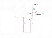
However, upon a short test (very low bias) with music...this channel sounds like pure crossover distortion (quite awful). Other channel is great.

Attached are the schematics. There are two darlington transistors in the bias circuit -- Q11 and Q18. Could one of those be bad? I know the variable resistor is fine, as I tested it (and even put the stock pot back in with the same result).

I have limited knowledge of circuit design, so any help you guys could provide would be great. Thanks in advance!! I really want to get this thing working after the investment I put into it.

I have double checked my work several times and don't see anything stupid I have done (though I have missed dumb mistakes in the past...)

Thanks again.

Attachments

  • 1.png
    1.png
    290.3 KB · Views: 597
  • 2.png
    2.png
    296.7 KB · Views: 585
  • 3.png
    3.png
    330.1 KB · Views: 561

Type 26 triode for sale

Hello all.
Recently unloaded my 26 triodes, but I missed one.
Its a Cunningham NOS/NIB type 26.
Can't post pics here so if you're interested PM me and I'll send them directly to you.
Original box is missing outer lid.

$ 25.00 plus postage to get it to you. I'll cover insurance to US. PayPal FF only.
US only unless you're willing to pay outrageous international postage/insurance costs.

thanks for looking and stay safe.

Cheers, Crazy Bill

ADCOM GFA-5500 High Power Supply Voltages

Hello All,

I just repaired an ADCOM GFA-5500 that according to the original owner was damaged due to a power surge, he said back in the 90's he sent it to a Service Center just to be told that it wasn't repairable, for sure it was since I just fixed it and I'm just a DYIer, well log story short is that according to the non accurate service manual and schematic that is all over the net the power supply is supposed to provide DC voltages of +73- and +60- but this one is putting out +89- and +78- instead, dangerously close to max out the capacitors, in the manual it says that all measures were taken with a 115VAC input and since I'm getting 125VAC out of the public mains I expect some higher values but not that high.

According to a person in Argentina some of these were manufactured with out of spec transformers and he said he has asked ADCOM and they said it was "fine" and suggested to adjust the bias to 10mv instead of 50mv...

Is anybody familiar with this issue?

Thanks!
Projects by fanatics, for fanatics
Get answers and advice for everyone wanting to learn the art of audio.
Join the Community
507,760
Members
7,887,261
Messages

Filter

Forum Statistics

Threads
406,173
Messages
7,887,261
Members
507,760
Latest member
The Fink