Hello all! After building valve amps over the years I decided to delve into solid state and rebuild an old project of mine. It was an amp I built back when I barely knew ohms law! It was to have a standard TDA2050 PA with a simple preamp that had good tone controls. No distortion, just a nice clean flexible amplifier.
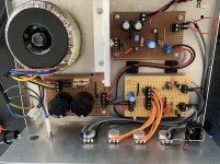
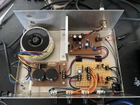
I built the PSU and PA boards, they worked perfectly. I breadboarded the preamp and that too worked nicely (although very noisy, but it was on a breadboard!). I then built the preamp board and assembled the amplifier.
On first switch on it would oscillate all the time, no matter what I did. The oscillation seemed to be in the preamp but I couldn’t pin it down, it seemed to be everywhere, I could even see it on the scope when probing the ground points! (Which all measured 0.1Ohms or less). I moved the volume control ground to the PA board and the issue was solved, except it would sometimes return if I turned up the volume past 7 and this is without any signal on the input.
Unfortunately whilst trying to solve the oscillation the TDA2050 chip went bad and no longer works. Which I find a bit odd as even though it was oscillating it was only drawing 400mA. I have an LM1875 on order to replace it, but wondered if anyone here had any ideas about the oscillation? The preamp board tests fine by itself and the PA board did. The only change I made between testing and assembly was the feedback on the TDA, I went from 22K/1K to 18K/1K. That’s still 25dB of gain though and within spec for that chip I believe.
Any ideas would be most welcome")
I built the PSU and PA boards, they worked perfectly. I breadboarded the preamp and that too worked nicely (although very noisy, but it was on a breadboard!). I then built the preamp board and assembled the amplifier.
On first switch on it would oscillate all the time, no matter what I did. The oscillation seemed to be in the preamp but I couldn’t pin it down, it seemed to be everywhere, I could even see it on the scope when probing the ground points! (Which all measured 0.1Ohms or less). I moved the volume control ground to the PA board and the issue was solved, except it would sometimes return if I turned up the volume past 7 and this is without any signal on the input.
Unfortunately whilst trying to solve the oscillation the TDA2050 chip went bad and no longer works. Which I find a bit odd as even though it was oscillating it was only drawing 400mA. I have an LM1875 on order to replace it, but wondered if anyone here had any ideas about the oscillation? The preamp board tests fine by itself and the PA board did. The only change I made between testing and assembly was the feedback on the TDA, I went from 22K/1K to 18K/1K. That’s still 25dB of gain though and within spec for that chip I believe.
Any ideas would be most welcome
Attachments
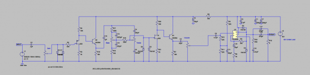
I should add, the oscillation isn’t any specific frequency, it’s various frequencies from roughly 500Khz to 2/3Mhz. After moving the volume ground I was able to control them by moving them up and down as I adjusted the volume control. The Bass and Treble controls didn’t seem to have any effect on them. My thoughts right now are either instability of the PA caused by the feedback change or a grounding issue.
D5 and D6 could cause J2 to oscillate as they'll limit the gate-source voltage of the JFET. I'd get rid of them. They don't serve any meaningful purpose there.
The impedances in your tone control are pretty high. I'd probably lower those and create a DC path for J2's gate to ground through a resistor rather than running that through the rather high (and variable) impedance of the 100 kΩ + 10 kΩ + bass pot.
It looks like the gain of your preamp is roughly 100 (40 dB). That's incredibly high. did you mean to add feedback? Or am I missing something fundamental?
I would add better decoupling on the power amp IC. As a minimum I'd go with 100 nF || 10 uF ||1000 uF.
For the preamp I'd use 100 nF || 10 uF. Since you already have the 100 uF there, you could probably get away with 100 nF || 100 uF.
I'm generally not a fan of single-supply designs, but I don't see any reason why the amp would not work.
I would probably start with the decoupling caps.
Tom
Hi
i agree to tom´s hint:
I would add better decoupling on the power amp IC. As a minimum I'd go with 100 nF || 10 uF ||1000 uF.
+ add the 10nF directly at the power chips legs under the pcb. i do not want to blame your work its fine but try the get the components as closed as possible and near tho the power chip. this pcb is fine..eBay mono LM1875 kit
chris
You should take the + and GND supply for the preamp from the PA board, not directly from the supply.
Also, grounding the case via the output GND could be problematic, given the high gain of the preamp.
Isolating the output jack and taking the GND from the preamp would be preferable
Also, grounding the case via the output GND could be problematic, given the high gain of the preamp.
Isolating the output jack and taking the GND from the preamp would be preferable
Thanks for the replies guys.
I do recall now that I did try removing J1 and Q2 and that made no difference, but it definitely stopped oscillating when I removed Q1. Unfortunately I can't remember if it stopped when I removed J2. Either way we know it's in that area!
I will sort the power decoupling, I was wondering about that. I'm also going to add a 22pf to ground on J1's gate and was thinking of adding a 47pf to ground on J2's gate.
I'll remove D5 and D6, I didn't realise they could cause oscillation. My reason for putting them there was to give some protection in case a large signal was sent into the amp, but really given I have a gain control up front they're a bit pointless! I'll add a 1Meg resistor between gate and ground as well. Would D1 and D2 not also cause similar issues for J1? I used them to limit input signals to 600mV.
With regards to the tone controls I was concerned about the high impedance, but when experimenting with lower impedances I just couldn't get the same wide range out of the controls. I'll revisit this again though.
As for the preamp gain, it wasn't exactly my intention to make it so high. With a 100mV signal up front and tone controls at midway (Log pots) it presents around 1V to the chipamp. I did have to lower the supply voltage by half to get the gain down and the bias correct on the JFETs. I wasn't really sure how else I could do it. When I first built it I had to use 33K drain resistors to get the bias right which gave me way too much gain.
Last edited:
Sorry Elvee, I didn't see your reply before I clicked submit!
I'm afraid the say the case GND is from the preamp as well as the Output Socket! I'll order a new Output Socket and sort that. As for the +, why would taking it from the PA board be more preferable than taking it straight from the PSU board?
I'm afraid the say the case GND is from the preamp as well as the Output Socket! I'll order a new Output Socket and sort that. As for the +, why would taking it from the PA board be more preferable than taking it straight from the PSU board?
Because the current draw from the amplifier induces inductive and resistive drops along its GND connection to the supply, and if you reference the input GND (=preamp) directly to the supply, it will appear as an input (and unwanted +feedback) to the amplifier.
Signals, power, control, etc should follow the same flow direction unless you have good reasons to do otherwise
Signals, power, control, etc should follow the same flow direction unless you have good reasons to do otherwise
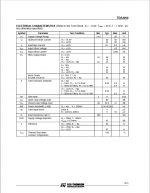
The only change I made between testing and assembly was the feedback on the TDA, I went from 22K/1K to 18K/1K. That’s still 25dB of gain though and within spec for that chip I believe
The minimum closed loop voltage gain of tda2050 is 30dB not 25dB. With 22k+1k you get 27dB, with 18k+1k you get 25dB, much less than min required gain
So moral of the story is always read datasheet first!
Last edited:
I'm not familiar with a feedback compensation circuit, have you got an example please?
I wonder if this is what I've seen in some guitar amps that use this chip.
And just so there's no confusion, I'm actually switching to the LM1875 chip. I couldn't get hold of a TDA2050.
I wonder if this is what I've seen in some guitar amps that use this chip.
And just so there's no confusion, I'm actually switching to the LM1875 chip. I couldn't get hold of a TDA2050.
Last edited:
I don't know much about this topic but it may help you... Fun with a cheap TDA2030A at only 6dB gain
On the other hand you can get tda2050 from Reichelt or Profusion at the rate of 1euro each. Tda2050 may give you little more power into 4ohm load but lm1875 is fine for bookshelf speakers.
On the other hand you can get tda2050 from Reichelt or Profusion at the rate of 1euro each. Tda2050 may give you little more power into 4ohm load but lm1875 is fine for bookshelf speakers.
Last edited:
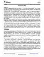
In the first post they are stating the same, "Most (if not all?) chip amps state in their datasheets that the closed loop gain has to be larger than 20dB or 24dB for the amplifier to run stable.". What you stated was the gain for the example presented in the datasheet.
In that thread they are going to the extreme and trying to achieve 6dB which is way below the minimum 24dB closed loop gain for the TDA2030. If you look at the datasheet component value tables for both the TDA2030 and TDA2050 they tell you how to increase or decrease the gain and also state it should be above 24dB. The LM1875 datasheet even states 10dB as the minimum!
In that thread they are going to the extreme and trying to achieve 6dB which is way below the minimum 24dB closed loop gain for the TDA2030. If you look at the datasheet component value tables for both the TDA2030 and TDA2050 they tell you how to increase or decrease the gain and also state it should be above 24dB. The LM1875 datasheet even states 10dB as the minimum!
You are generalising everything and that's not good. I was not trying to prove you wrong but trying to help you. Which i stated earlier is not example but TEST circuit (please read first line of page no.3 of tda2050 datasheet), the manufacturer has published all the information based on that TEST circuit(page 1). Yes the gain must be above 24dB and that's for stability reason. To achieve best stability and performance you must set the gain to 30dB as minimum as recommended by ST.
Btw which lm1875 datasheet did you read?! That's voltage gain of 10V/V or 20dB(min), not 10dB!
Btw which lm1875 datasheet did you read?! That's voltage gain of 10V/V or 20dB(min), not 10dB!
Attachments
Apologies, I appreciate you’re trying to help me, but I still don’t understand your reasoning for the minimum gain. For the TDA2050 the minimum is 24dB for stability, but why is the minimum 30dB for the best performance? What do you mean by performance? In my case I lowered the gain because I wanted the Power Amp to accept a 1V input signal.
And good call on the LM1875, I thought that gain figure was a bit low.
And good call on the LM1875, I thought that gain figure was a bit low.
My new parts arrived today! I did the following:
- Replaced the blown TDA2050 with an LM1875
- Removed the diodes from the J2 stage input
- Added a 1Meg resistor from gate to ground on the J2 stage
- Added a 47pf from gate to ground on the J2 stage
- Added a 22pf from gate to ground on the J1 stage
- Added a 100nF ceramic cap on the power rail on the preamp board
- Added a 10uF electrolytic on the power rail on the PA board
The result…...it works! Still a few problems but it works. I still have changes to make. The remaining issues:
- The amp will oscillate with all controls on 10, but stops if I turn the treble down a bit. It does this when testing the preamp board by itself, so pretty sure it’s not the PA.
- The volume pot crackles. I measured 1.4VDC on it which I believe is coming from the PA board. With the volume turned down I measure nothing on the input of the pot, so definitely the PA side. Leaky cap maybe?
- The amp pops during turn on and a little bit during turn off. I understand this can be normal for these chips and have a few ideas for stopping it. More testing is needed first though.
- I still need to replace the speaker socket and may also move the preamp power rail and ground connections to the PA board as suggested.
I only tested it quickly tonight with my scope, sig gen and guitar. I measured 25W clean at full power and with the guitar it sounds pretty good. Quite pleased with it.
Just ran some more tests and confirmed the 1.4VDC is coming from the PA board. I believe it's the 4.7uF input capacitor that is leaking. With my meter across it I measure 65K one way and 22K another way. It's also affecting the DC offset of the LM1875, the output is at 18V when it should be 23V. This explains why when testing the amp for power it will start to asymmetrically clip.
I'll get another capacitor in there to test. Even more annoying is it's a brand new cap I bought specifically!
I'll get another capacitor in there to test. Even more annoying is it's a brand new cap I bought specifically!
- Status
- This old topic is closed. If you want to reopen this topic, contact a moderator using the "Report Post" button.
- Home
- Amplifiers
- Chip Amps
- TDA2050/LM1875 Project - Oscillation issues