Fostex FW 305

hi team,

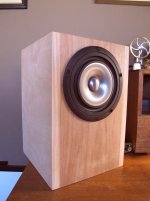
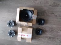
I managed to found 2 FW 305 and I'm thinking what to build w/ them - they will complement a backloaded horn Fostex 206 - so I'm looking at something fast. Amplification will be bi-amp w/ a dedicated Firstwatt amp (F5).
I was looking at the official DIY enclosure from Fostex and I wanted to check if any one has more creative ideas as well 🙂

Thank you, Fred

Help me ID this potentiometer?

Hi there,

I have an old Cello Palette Preamp and the main level pot has a weird lull/jump at 5 (12 o'clock) - right around that point one channel drops out slightly and the at 6 (1 o'clock) the volume jumps MUCH louder. There is no crackling so I'm not sure it would be a dirty pot. I've only ever changed out an alps blue 100k pot before, but this one I'm not familiar with. Its a 50k 10% but small white box shape and appears it might be even soldered down to the board beneath. Any help appreciated!

IMG_2597.jpeg

6p14/EL84 13W Magic Eye From ebay

Hello Community,

I'm trying my hand at building a kit from ebay. Eventually, I want to build something much nicer, but thought I should get my feet wet first. I'm at the infancy of this electric adventure and my knowledge is very limited.

That said, I've tried watching as many related videos as I could find and read extensively here on DiyAudio to try to solve my problem. I've not been able to do so. So I turn to you for help.

After putting the amp together, switching it on to no (very little) hum and no smoke. I turned up the volume and had music. I was stoked. However, I quickly discovered that the right channel is playing much louder than the left and the magic eye on the right is inactive.

So I bought an oscilloscope.

It seems the signal is clipping on the right channel at about half volume. So I feel like the left side is wired correctly and the right not.

I tested voltage throughout. Left and right do not show the same voltages.

At pins (R)1 and (L)6 on the 6n1 (ecc85), 1 shows 88.4v and 6 100v.

R: 3 and 8, 1.5v and 101.9v
L: 8 and 3, 1.65v and 95.7v

C1 210v
C2 91v
C3 199v
C4 101v

On the tube side of resistor 6 and 8, 9 and 10 there is a difference on both sides.

R6 87.7v
R8 100v
R9 91v
R10 101.7v

Pins 3, 7, 9 on the 6p14s are all very similar

R
pin 7 on both is 311v

L
pin 7 on both is 312v

R
pin 3 on both is 10.5v

L
pin 3 on both is 10.3v

All pin 9s are 298v

Finally, there is no signal reaching the magic eye circuit coming from R5. There's a faint signal reaching the resistor but nothing on the other side.

The signal seems to already be at half coming off pin 3 before going into R3.

There is equal signal at R1 and R2

When I hook up the signal generator, the right channel signal can be heard much louder coming from somewhere in the amp (output transformer?)

Thank you for any help or ideas you can give me.

Will in Korea

Attachments

need some help with the drivers

Yo guys , sorry for my english . I made a 2 way speakers time ago , not so good tbh . I wana make a 3 way loudspeakers now ,but kinda cheap .Is hard to get some good speakers in Bulgaria , also i dont want to order them from far away , cose they may not come in one piece .I like those for stupid reason they look good ( dont want my wife to throw the speakers out of the window ).Found this speakers :

MONACOR: SPH-8M

MONACOR: SPP-125

MONACOR: DT-140 this one is 4 ohm
Exproject
- Говорители - Високотонови - Monacor - DT-109
prefer this one 8 ohm

the middle is 92db , is this gona be a problem for making the Crossover , cose i dont have much skills in electronics ( im biologist ) .
Is there a software wich is free and can calculate a box volume for 3 ways , and to tell me shoud i separate the middle from the woofer and this kind of stuff ( i can solder the componets 🙂 ) . tanks

my Amp is 8-16 ohm but have some problems , gona buy new one soon

Adcom GFA 545 transformer buzz

A friend loaned me an old Adcom GFA 545 that he bought years ago and never even plugged it in. I cleaned it up a little, checked the gain with a signal generator and oscilloscope (got 27.8db) then hooked it into my system.

I notice that there is more transformer buzz coming from the unit, not the speakers, than I am used to hearing. Is this normal with this model?

Bohlender Graebener plus Markaudio

Still fascinated with dipoles, Bohlender Graebener, and speaker building in general.
I've putzed around with several designs, and am now about ready for a more permanent solution.

I've also decided I don't really care for MDF, and chose engineered spruce panels for the bass section.

I've used an H Frame, as a tryout, and decided I'd rather do a U Frame.

Here's a shot of an earlier attempt at a planar mid tweeter array, with some inexpensive high Qts 10" woofers, liked it, but ultimately, the woofers were just not really accurate.

Attachments

  • image.jpg
    image.jpg
    512.2 KB · Views: 533

Telefunken NFLU 325 600 Ohm

I am in the process of arranging a meeting with an EE, to discuss options on using a Tranx to change a Valve Power Amp that is in use to a Balanced Power Amp.

Has anybody compared the Telefunken NFLU 325 600 Ohm Tranx to other more modern production choices.

Are there other Tranx options that can improve on the Sound Quality when included in a design.

As I am a EE Numpty, totally dependant on support from others,
the Tranx Method to produce a Balanced Design seems to be the least complicated to inherit.

ID Transformer Help / testing

I have a transformer that I do not know where it came from. The only factory marking on it is 139195. In masking tape is written 350 - 0 - 350, 12.6 VAC, 5(something) heat + 5V LI (something). I would get a photo but the camera on my phone is not working. Its fairly beefy transformer, kinda looks like a dynaco transformer just on steroids.

Is this transformer worth building a tube amp around?
How do I test said transformer?
What are my amp build options?

Bypass internal preamps on Tascam Portastudio (Cassette)

*** MODERATORS - PLEASE EDIT MY POST - I MEAN INTERNAL PREAMPS NOT INTERNET PREAMPS (typical auto spell....)


I don’t know if this is the correct section to post this, but anyway.
I am wanting to record to cassette. I am thinking about buying a tascam portastudio as they record at double speed. However, I will have my own preamps and don’t want the signal passing through the tascams preamps.

Are there either any portastudios that have this feature, or any known mods to bypass the built in preamps?

Does the sub-in use the built in preamps?

I can’t find any portastudios that have a line in...

RTi12 Crossover replacement parts

Am looking to replace the capacitors in my rti12 crossovers.

I can find exact replacements for the bipolar electrolytic ones, but I cannot find the 9.0uf 100vdc film capacitor. Any ideas for a similar replacement? Oh and is it worth replacing it or would it likely still be in spec.

rti12-film-cap.jpg" alt="rti12-film-cap"


Also what value is the resistor? I see it's 5 watts, is the resistance 2.7ohm?
rti12-resistor.jpg" alt="rti12-resistor"


Thanks!

Help needed with Quad ESL57 Speakers

A few (5 or 6) years ago, I bought my third pair of the Quad ESL57 and they stayed in the box unopened until a couple of weeks ago. The last owner sold them because he claimed that one of the speakers was not playing as loudly as the other! He had not bothered to have them looked at since he had already moved to a smaller apartment and enough space was not available for these speakers.
Since then, my first pair of my ESL57 (did not have any problems) got sold last year and then I repaired the second pair that had a leaking treble panel that caused low sound output even after the EHT power supply was refurbished. So I am quite familiar and openly grateful for the information provided by Sheldon Stokes, Keith Snook and others.
Hence we come to the problem at hand, and I will describe it as best as possible: I unboxed only one of the speakers and connected it to my system, hoping to compare it against a system that was already there and working well over a long period of time. Very slowly, it came back to life and played the way I think it should! The speaker looks like new, no dents on the shiny front grille, an extremely well preserved item whose serial number dates it back to 1967! I left it unplugged overnight. Next morning, coffee cup in hand, 20 or so screws later the back cover with the horse hair comes off….I am looking inside at pristine speaker panels with hardly any dust and original 1972 dated repairable EHT power supply and original audio transformer components. I try to measure the EHT with a normal Digital Voltmeter and the treble voltage goes overload and the bass EHT barks back with a crisp spark before I can even touch the terminal! I put the back cover on again and test it…..all is well. Still shaken, I order a High Voltage probe.
Next, I unboxed the second speaker and it too plays as well and equally loudly after charging up! The next day, I open it up and it too seems all like new inside. The only difference being that there is the very old epoxy version of EHT power supply that cannot be refurbished.
I cannot figure out if there is a problem with them, except when I power them off whilst still playing….The speaker with the old epoxy EHT power supply begins to play more faintly after 3 or 4 minutes compared to the other.
Considering the fact that both speakers do not show their real age, I am presuming that they were completely refurbished but I fail to understand why anybody would put the obsolete EHT power supply on such an undertaking where even the Bulgin mains plugs look new!
Does anybody know if the obsolete EHT supplies less EHT voltage compared to the newer ones?
Any help or suggestions will be greatly appreciated.

Technics EPA100 modifications

I am waiting for bits to get back to making the servo linear so while I had nothing to do I decided to make some modified parts for my EPA100.

The stub is solid brass and the CW is stainless steel with an aluminium locking collar. The additional mass of the SS CW also moves the centre of the CW closer to the pivot. One thing I didn't like with the EPA is the loose fit of the stub into the arm pillar. The new brass stub is machined to a close slip fit and the CW M12 x 1.25 thread is precision machined so there is no slop in the CW, which is then locked with the aluminium locking ring.

I also machined a damping trough which is fixed to the underside of the arm clip so in the unlikely event I decide to sell the EPA removing the CW and damping system leaves no marks on the arm.

The plots are 300Hz tone band 6 on the HIFI News test LP. The 8.5Hz sidebands are totally gone. I was not expecting this to be an upgrade I thought the change would be inaudible but this is not the case as the measurements show.

I still need to dial in the damping but listening to the TT now.

.

Attachments

  • IMG_20210105_170409995.jpg
    IMG_20210105_170409995.jpg
    676.8 KB · Views: 409
  • IMG_20210105_170359238.jpg
    IMG_20210105_170359238.jpg
    794.2 KB · Views: 403
  • IMG_20210105_105647337.jpg
    IMG_20210105_105647337.jpg
    705.3 KB · Views: 379
  • IMG_20210105_105758814.jpg
    IMG_20210105_105758814.jpg
    700.7 KB · Views: 400
  • 300Hz_OEM1.jpg
    300Hz_OEM1.jpg
    219.1 KB · Views: 413
  • 300Hz_CW_damp.jpg
    300Hz_CW_damp.jpg
    209.5 KB · Views: 185
  • 300Hz_OEM.jpg
    300Hz_OEM.jpg
    205.7 KB · Views: 198
  • 300Hz_CW_damp2.jpg
    300Hz_CW_damp2.jpg
    210.8 KB · Views: 200

Emerald Physics CS2 Speakers

For Sale: Emerald Physics CS2 Open Baffle Speakers in perfect condition with Behringer programmed DCX2496 crossover and original boxes.


Very interesting speakers that actually surprised me...just not quite as good as my Quad ESL...so up she goes...need two stereo amps to drive these...I used my homebuilt 4 channel ICEPower 500ASP / 500A amp and sounds very very dynamic...very Live-like...

Pick up in West sub of Chicago - would rather not ship....

How's $875?

Attachments

  • 649646685_thumb_ae24c73a0021daa5fbd89f535f912c13.jpg
    649646685_thumb_ae24c73a0021daa5fbd89f535f912c13.jpg
    7.5 KB · Views: 868
  • 649646685_thumb_879d66524bccacf20246a3807cc2ceae2.jpg
    649646685_thumb_879d66524bccacf20246a3807cc2ceae2.jpg
    7.7 KB · Views: 868
  • 649646685_thumb_7690dae75a3783635df1b847e30bc815.jpg
    649646685_thumb_7690dae75a3783635df1b847e30bc815.jpg
    11.3 KB · Views: 856

Cabinet Port Size Advice Needed!

I have a question for those of you who know about building ported speaker cabinets. I want to use this Celestion Coaxial speaker for a full-range guitar cabinet intended for amp modellers and acoustic guitars:

Celestion F12-X200 - 12in Ceramic Full Range Speaker

Here is the DIY cabinet that Celestion recommends for it:

BUILD THIS: F12-X200 1x12 Cabinet Design - Celestion

Since I have a couple of cabinets that are close to this size, I emailed "Dr. Decibal" at Celestion and asked him the following:

"The internal dimensions recommended by Celestion are approx. 21" x 15.5" x 13.5". I have a cabinet with an interior volume of 18" x 14" x 13.5". It says in your promotional material that this speaker will work well in a variety of enclosures. If I use the cabinet I have and add the recommended port, can I expect good results?"

To which he answered:

"I don't see why not. It might be worth finding some cab design software online to help you calculate a sensible port size. This is just one design. You can get great results simply from putting the speaker in a standard cabinet, or design your own with the parameters provided on the product webpage. You can use whatever material you like."

I have no experience with speaker cabinet design software. Can someone recommend a proper port size for the two empty cabinets I currently have? (Dimensions listed below.) Which cabinet is a better choice? I am capable of making the new baffle with a port as well as closing off the back of the cabinet I choose, but I don't know how big to make the ports. I would prefer the cypress cabinet because it is very light. If the depth on the cypress cabinet is too great, I could cut it to make it shallower.

Cabinet 1 (The lightweight preferred choice):
1/2" Dovetailed Cypress (similar in density to Pine)
Interior Dimensions, length/height/depth: 18" x 14" x 13.5"

Cabinet 2 (My second choice, quite a bit heavier):
3/4" Birch Plywood
Interior Dimensions, length/height/depth: 20.5" x 13.5" x 9"

I would appreciate any advice re. this, thank you very much!

What does mean frequency range of a PA?

My Yamaha two-way 10 inch pair of speakers are designed to play a frequency range from 55Hz to 20kHz at +/-10 dB, 129SPL per speaker, measured in a distance of 1 meter from the speaker.

Questions:
If my speaker plays in 55Hz it has no difficulty to play above 80Hz will I have any troubles if I apply a 80Hz Hipass to them and send a 80Hz lowpass to a 18 inch subwoofer? If these speakers are designed to play from 55Hz, they are a good match for a 18 inch subwoofer, or do you think a 12 or 15 inch speaker is better?

Moving on from CHP-70.2

I've been enjoying a pair of CHP-70.2 in Scotts 306x176x226 compact vented cabs. They sit pretty much on axis on my desk and, as advertised, are really nice for extended listening. However the 7k drop in high frequency has been bothering me for a while and so I think its time for a change of driver from further up the MarkAudio food chain.

The Pluvia 7.2 HD looks nice and has much higher frequency extension. I bodged a vented box sim of 14.3l and 50Hz. This gives a F6 of 40Hz.

Can't seem to find much on the Pluvia 7.2HD. Are there any boxes from the Dave/Scott/Scottmoose universe I've missed?

MKIII x4 build or?

Hi!

I’m looking at changing my main system to all tubes and need some suggestions.

I currently have a Micromega PW400 amp (400w into 4ohms) bi wired (the amp has 2 outs/side) to my PSB Gold i (completely rewired and rebuilt xovers).

The setup sounds quite nice, especially with a custom built tube buffer between source and preamp. For a while, I wanted to get a second PW400 to do a proper biamping, I used to see them regularly second hand for a good price but of course, since I decided I needed a second one, I’ve been unable to find any for sale in Canada…

Anyway, while the amp is great and has enough juice for the power hungry PSBs, it also sounds a bit boring/sterile. Since I enjoy building things, I thought I’d build 4 tube monoblocks for the speakers: 1/woofer and 1/mids-tweeter.

I was thinking the MKIIIs would be good candidates. I’d use the modified circuit by tubes4hifi, a pair of KT88s and 12BH7s (maybe e80cc) and a triode switch just ‘cause.

If I was to go with these amps:
-What OT would you guys recommend? Is there anything better than the Dynakit or Triode transformers?

-I’ll build my own chassis out of MDF and steel plates, any designs you’d recommend? I kinda like the look of the Thomas Mayer 845 monoblocks.

-The PSBs are power hungry, so I can’t do EL84SE amps… I think 4x 65w is good enough. Would you guys suggest another design for a PP KT88s amp that would sound better than the tubes4hifi version of the MKIII?

THANKS

Denon avr888 amp section; where to input audio

Imaged below is an amp of a denon avr888.

I want to input unbalanced line level into the amp from a separate pre-amp.


Connector CX510 is from the pre-amp, so I thought maybe pin 5/6 highlighted in yellow would be where the line level audio to be amplified would be. But with no connection to the "native" preamp it enters protection mode.

Image from service manual for Denon AVR888 around page 183.

Denon-AVR888-AMP-schem-3.jpg"


Is anyone able to explain the signal path in the above? Also I have a cheap usb oscilloscope, so could feed a signal and poke around though would need direction on where to poke 😀

power switch on nad amp

im working on an amp at the moment that is blowing fuses and when i took the protective sheeth off the mains cable-to switch i found this.one of the transformer leads was held together with masking tape! disgracefull, anyway one thing i noticed is that the neutral is being switched,surley this isnt right or common practice is it?


there is no unswitched supplies at the back of this amp like some models had

Attachments

  • SW 1.jpg
    SW 1.jpg
    355.7 KB · Views: 131

Sansui AU-666 Driver Transistor Equivalent

Hello everyone,

This early 70's amplifier of mine uses Hitachi drivers, 2SC708/2SA537 pair.
I'd like to be given some suggestions as to what would be an ideal replacement, these are also used in other Sansui models, the Eight being one example.
Suggestions for current available parts and obsolete parts are welcomed, I do like using well regarded Japanese transistors in my equipment if I'm fortunate to find them.
Previously I upgraded the 2SC871 to 2SC2240 and
CDC8002 to 2SC4793, there's no doubt of the improvement with those new parts in.

I'll do my best to upload the originals data sheet and the schematic of the amp.

Thanks in advance.

~Ben

Attachments

  • Screenshot_20201117-090224_Chrome.jpg
    Screenshot_20201117-090224_Chrome.jpg
    419.4 KB · Views: 264
  • Screenshot_20201117-090230_Chrome.jpg
    Screenshot_20201117-090230_Chrome.jpg
    372.1 KB · Views: 234
  • Screenshot_20201208-142149_Drive.jpg
    Screenshot_20201208-142149_Drive.jpg
    335.3 KB · Views: 238

Developing a Regulated Dual Rail Power Supply For FirstWatt Amps

Developing a Regulated Dual Rail Power Supply For Pass DIY Amps

Why did I choose bipolar transistors?

1) Smaller voltage drop across transistors compared with mosfets, which means less heat generated/wasted
2) A larger variety of suitably matching npn and pnp devices
3) I have a stack of bipolar transistors in my stash of parts that will probably never be used in an amp circuit.

I have not had the chance to test this circuit in the lab as yet, and would appreciate advice on improvements that aren't radical changes to the original circuit.

Here is the positive half of the circuit

Sorry about photobucket no longer showing images.
I will update here later with full documentation eg pdf or similar


Darlington%20Supply.png

Threshold SL-10 & CAS-1: loudness and Input sensitivity

Hi everybody,
I found that SL-10/CAS-1 for a good price, and they work very well! I use them with my Infinity Quantum 3. I'll recap them later, since I spend too many time and money to recap/refoam/fix the Infinities.
Now, my problem is that volume control is too sensitive: on first position it's already too loud. (I use a NAD C521).
Is there something wrong, or do I have to build an attenuator? Also, I have too much bass and subs, but maybe it's a Quantum 3 characteristic...
What do you think?

STETSOM 10k2, the capacitor burns out

Hello everyone! I have to ask for help with the solution of the issue. An acquaintance brought the amplifier for repair, one capacitor constantly breaks down. The capacitor starts to get very hot when we load the amplifier over 20-30% of the power. Amplifier STETSOM 10k2.
_OUA3-Y5QXY.jpg

T6qtuf8UH2I.jpg

ELMaMY2evMM.jpg

An externally hosted image should be here but it was not working when we last tested it.

EgUKEFp2o2U.jpg

JBL Crown Monster A6000GTI problem with hip4081a

Hello, friends.
Came to my hands JBL Crown A6000GTI with the burned control part. 79l15a and 7915 burned and a high voltage went and took everything in its 15v line. I'm replaced all LM319, IR4427, UC3825, logic chips HC74A(changed to 74HC74), AC04(changed to 74AC04), as well as HIP4081A which tells the power supply. But the power supply still does not start. I have generation at the output of the UC3825 = 450Hz, this line goes to 5,6 pin on the HIP4081 chip, on the 2,7,15,16 pin I have a voltage of 14.9v. 4 PIN is GND. 3rd pin DIS I have a generation of 900 + Hz. if I'm not mistaken, this is a logical level, it is responsible for the open / close outputs oF the chip. but I have nothing on the output of the IC. there is a suspicion that it is educated or burned out from static voltage. Has anyone encountered such an amplifier? can you give recommendations?

cts6-jTSrnE.jpg

r9HoYM-iEF0.jpg

UB2FSxHyvWk.jpg

pwEFCyftMvw.jpg


On the 3rd pin on the IC HIP4081A
7v7q6rjB9bk.jpg


On the output of the UC3825 14,11 pin I have sinus = 450Hz
O17CFHGulaY.jpg


On the IR4427 on the 2nd and 4 pin i have sinus =125kHz
2ic 4427 al linputs are connected in parallel but outputs gone to 2 transformators
M3wtVoJFCFs.jpg

Quick soldering technique question (with image):

Hi,

I am new to 'real' soldering (like beyond doing random wire solders over the years) and just finished a Bottlehead kit, and the ACA (and did some practice kits before those so I was not learning on things I cared about!). The Bottlehead did not have any PCBs, but the ACA of course does...and a PCB that is actually passing a lot of current compared to most PCBs (for example what might be in a preamp or a $15 practice kit with LEDs).

Based on various things I read online, and the YouTube videos suggested by the makers of the kits, I was deliberate and purposeful in making sure I didn't just have a nice solder joint on the 'top' (where I was touching the iron), but that I also flowed enough solder into the joint that it fully penetrated the PCB and reached the other side...as the image shows. This was stressed as important (especially for higher-current) because the trace is very thin and this provides a much better connection.

Can you verify this is 'correct' and a best practice? Is there every any reason you would not want to get a good flow like this (assuming you are not planning to disassemble!)?

Thanks!

i-gVk98wT.png

assembling a LITE LS-69 Hybrid Balance pre-amp

seems that it is reversing polarity...

why is that? and what's the consequence of using it with different switching amp like Red Dragon M500MkII and class d audio SDS-258?

its a bummer if i have to reverse loudspeakers polarity...

([FONT=Verdana, Arial, Helvetica, sans-serif]Hybrid tube balance pre-amp using FET input, tube cathode follower output)[/FONT]

http://www3.telus.net/gagnonma/LS69.jpg

What tubes to use with these 1k5 50 watt SE transformers?

I bought these ebay bargain transformers a few years ago, and originally planed to do an 859 style amp with 3 paralleled 509s, to give about 40 watts. But time goes by, and I packed them away, but still their memory lingered and in their absence I eventually convinced my self they were from an audio note parallel 300b amp. Dug them out again yesterday to do some measurements. I convinced myself wrong. They are made by Trans-tronics.

Anyway what tubes to use, I have fairly modest aspirations, 30 watts output should be adequate, rough calculations would suggest a HT of about 500 volts, and 200mA current. I am thinking triodes would be nice, maybe a couple in parallel, but what.

Pleas help me with some recommendations of something hopefully fairly cheap and maybe directly heated? but not essential and probably not 6c33.

attachment.php

Attachments

  • setx.jpg
    setx.jpg
    61.9 KB · Views: 717

FPGA-based DSP sound processing platform

Hi there,


I'm developing an FPGA-based DSP sound processing platform.

I am planning to do this as an OEM PCB board.


Short brief about the DSP processing platform.


1. Total number of channels processing - 128.
2. Processing path - 64 bit float point (IEEE 754 double precision).
3. Sampling rate - 96 kHz.
4. Latency processing - about 200 microsecond (20 tick 96 kHz sampling rate).
5. Input channels - 128 with digital trim, polarity, LPF/HPF filters, 8-band parametric EQ, compressor, gate and limiter section (maybe in future - multi-band), channel gain and panorama.

6. Mixing matrix - 128x128 with gain crosspoint.
7. Output channels - 128 with 8-band parametric EQ, 32-band graphic EQ, compressor, gate and limiter section.
8. Input/Output interface - master multichannel I2S (16 input / 16 output line (8 channels in each line), 24.576 mHz bit clock, common bit clock and frame sync signals).


It's possible to change the internal architecture during the development process.


I hope this project will be interesting for someone. Also I would like to hear anythings from interested people.

NAD T743 - converted to analogue stereo power amp

So after posting this thread a while ago and losing interest in the project since then, COVID lockdowns and go-slows at work have given me the time and space to try and work this one out again.

I came across this video on youtube that was pretty close to what I needed, and provided some good inspo.

The main difference between his and mine is that I always suspected it was more the 'brains' rather than the actual hardware that was busted on my unit, so I was looking for a way to brute force it and inject a signal directly into the amp circuit.

First thing was to test the power supply. After jury rigging the standby switch to bypass the front panel, I found I was getting a reasonably consistent +- 50 volts on the primary, however all the secondary voltages appeared to be reading low. At this stage, I'd already comitted to bypassing the brains, but it could turn out that it was simply low voltages to that side of the unit that was causing me the issues. So Lesson Learned there. Mine isn't undoable, but for what I want I don't think I'll bother as I do have another NAD unit to work on (a T775) in the future.

After that, it was a matter of tricking the speaker relays to turn on. In testing these I may have fried the main front L/R relays by putting the reverse voltage on them (oops). I 'think' it's repairable, but I proceeded with the surround speakers anyway as each channel is basically the same circuit. My power source is a LiON battery, with some leads soldered onto where the relay connects to the board. I wired in a little rocker switch so I can turn this on/off as needed.

The grey lead coming from the pre-amp board is where the audio signal come in. To get me started, I just snipped this and spliced this onto a headphone to RCA lead that I also snipped, and just wired it in. Audio source is spotify on my phone, and volume is controlled there as well.

Et Voila, IT VERKS!!!!

Note these photos are dodgy as hell as this is just a bench test, but I'm ecstatic that the proof of concept is working. One cool thing I've noticed is how my current limiting lamp throbs in time to the music.

Next steps will be:

1. General housekeeping of wires for neatness and safety
2. Work out where I can obtain the required voltage from the unit itself to trigger the speaker relay, rather than relying on an external source.
3. Consider a volume control dial on the unit itself, rather than relying on the input (but this isn't a big deal for me).
4. Consider wiring the audio input to the factory front-input RCA plugs.
5. Gut the rest of the unit to remove superfluous bits and pieces, and mount everything neatly.

Happy for advice, comments, criticisms, etc. Go for it.

Maximizing bass output with zero vessel gain

So, it’s been a minute since I designed an enclosure but I have a project that the wife has placed on me and I would like to draw on this knowledge base. I know this is related to a vehicle application but please hear me out.😁

My wife has a newer Jeep Wrangler that she drives around “topless” and of course the bass reinforcement simply disappears.

I am looking at designing a subwoofer using one of 2 subs I have. A JBL P1022 10” sub or a Sundown Audio SA12v2 D2. I would also like to protect the drivers as much as possible. So to maximize output and protect the driver I am thinking bandpass.

I am not worried about low lows. So <40 hertz I am really not concerned with.

Which type would you recommend? Single reflex or dual reflex.

Also a question regarding dual reflex bandpass port placement. Is there a cancellation effect if both the high tuned and the low tuned are side by side?

Thanks for any help and advice.

Does servo sub excite room mode to lesser extent?

Hi,

We know that when there is a room resonance near the frequency of port tuning frequency of a subwoofer then both the resonances couple resulting in boomy bass.

So, does it mean that if one were to test the same situation with a servo sub of some kind, lets say a current driven servo sub (ACE bass etc) then due to the greater control of the driver at port resonance, the boominess can be reduced atleast at one frequency?
If yes, then will it make an audible difference?

Thanks and Regards,
WonderfulAudio

How to get a message through

This post is not meant to harass or offend anybody - but rather a question on how to be polite and respectful and still get a message through.
Over the last 6 month I have the feeling that I see a growing number of questions related in particular to helping beginners designing and building diy audio getting stuck at the questioner rejecting proper help.

I will not refer to specific threads, but the one that prompted me into this post, resulted in a knowlegdeable forum member being very precise and blunt in explaining the questioner that a lot of people had offered valid help, but the help was rejected because the questioner did not accept that the original design would not work.

I think that particular reply was very clear and I have previously been tempted to post similar replies to some of the threads, I've been involved in.

"Tempted" - because after consideration I did not write the reply as I feared that I would start a storm and some would have felt harrassed.

So maybe I am asking about others views on this - or I am just venting some steam😉

Cheers,
Martin

Dynacord sv 17 amplifier

Hello, I have a Sweet little ‘lunch box’ amp that I am renovating at the moment. A Dynacord sv 17. I want to use this as a guitar amp and I thought I would go through it and change the electrolytic capacitors and any other parts that don’t measure up to par. Everything looks original and judging by the dust inside, untouched. Now I have come to my first hurdle. There are two large can caps between the transformers. Both are marked Dynacord and have values of 32+32/550v and 32+32/385v. The problem is that according to the schematic it should be 32+32 and 16+16. At first I thought the second one might be wired up in series, but it doesn’t look like it. Before I order some cans from Jan Wuesten I just wanted to ask if I should go by the schematic or replace the old cans with the same values as found in the machine? Maybe someone here has some experience with these amps.
Thank you for your help!
Lucas

crossover rebuild

An externally hosted image should be here but it was not working when we last tested it.
I'm doing a cap replacement on 4 wharfedale airedale sp speaker crossovers.
I would like to change all the caps with film caps.there are 7 caps per board and I don't want to go broke or over spend on the quality.I hope you can give me a little guidance and tell me if I should change the resistors as well. thank you for any help. Scott

Fisher 500C free to good home (L.A.)

I have a partially restored Fisher 500-C that I no longer have room for. It's free to anyone who will either pay for shipping, or come and pick it up from where I live in LA.

I've done a bunch of electronic restoration on it, focusing on the power supply and power amp sections. I've replaced all the critical caps and the tubes are all NOS. I've been using it as a power amp, and the sound is fantastic. The phono section and the tuner still need work. And the front panel is not exactly pristine. So it would be great for someone who wants to use it as a power amp, or someone who wants to continue the restoration. As is, it's dead silent, completely reliable, and sounds great. I may be able to find some schematics I was using during restoration, not sure. But I think they are available anyway.

It's kinda heavy, so won't be cheap to ship anywhere. If you're interested, but live like 2 hours away, I would consider meeting somewhere in the middle.

If nobody is interested, I will probably pull the tubes and sell them on eBay, and junk the rest.


Edit: Thanks to the folks who replied. ghettocowboy came by to pick it up.

Which speakers do I need / want?

Hi,

Sorry if this is in the wrong forum-category, could not really find the appropriate one.
Recently, I was gifted an amplifier and a battery board.

The amplifier board:
Looking for an Arylic Up2Stream Amplifier? - SoundImports
The battery board:
Looking for a LBB-5S Lithium Battery Board? - SoundImports

I want to use these to build a portable speaker for my football team.
As I'm quite the novice (been researching into speaker building for months but still feel like I don't have the faintest idea of what I'm doing), I could really use some advice on my choice of speakers for this build.

I want to keep it as simple as possible, luckily the amplifier has a crossover built-in so I want to just buy 2 full-range speakers for the 2 (50w) channels and a subwoofer for the 1 (100w) channel.

The user manual for the amplifier states this about the speaker power output:
2x50W@4Ω + 100W@2Ω BTL load at 24V
2x30W@8Ω + 75W@4Ω BTL load at 24V
2x22W@8Ω + 48W@4Ω BTL load at 19V
2x15W@8Ω + 30W@4Ω m BLT load at 15V

As I have (5) 18650 batteries at 6.7A and the battery board output states 21V, I think I'm correct to presume the maximum output would be 140W total and this would at max be outputting 2x35W@4Ω + 70W@2Ω?

After watching tens or hundreds of youtube videos, I still do not know which wattage speakers I should be searching for.
I've seen reviews for this board where someone just connects 15 watt speakers with a 20 watt subwoofer, sometimes a 300 watt subwoofer, and everything in between.

My problem is, as this is for a football team, I need speakers which can handle running at 100% volume. I'll try to avoid that, but I'm sure someone will always crank up the volume when I'm not watching.

What would be a good choice?
- What wattage and ohms for the 2 channels?
- What wattage and ohms for the 1 channel? (2 ohms is not an option so at least 4 ohms)

As I said before, this is for a football team so it needs to go very loud, so I'll have to check the efficiency and what not, but the 2 questions above are the ones I'm struggling with the most.

Sorry for the long post, and thanks in advance for everyone who takes the time to read my question.

Power Tool Battery Maintenance - Best Practice?

Over the years I've purchased many, many battery operated power tools which suffered the same fate; owner used (or never used...) for a bit, neglected to care for the battery, then when it no longer works, threw it out.

It seems most of these were designed for the active construction worker, who uses the tool daily and expects good performance. In reality, many such tools get used a few times every few months for some odd job. In between these times, the battery doesnt know what to do with itself, so it rolls over and dies.

I'm of the latter camp. I want my tool at the ready, whenever I happen to need it, which could be at an interval in weeks of time. What's the best practice for maintaining the battery in good condition?

A fellow at work (also an audiophile) once said that he stores NiCd - or was it NiMh - shorted with a resistor. Then charges when needed. I notice none of the commercial tools do this; you dont get a "shorting cap" as an accessory. So I'm skeptical, even though the guy may have been right.

Thoughts?

The most promising tool in the inventory so far

I've just bought the ORTUR LM2 20W laser engraver.

At $300 it is a seriously impressive piece of kit that performs many of the jobs that have been difficult - to say the least - at the DIY level.

Finally I have a machine that can produce PCBs with repeatable accuracy.

With a bit of playing it can also produce front panels, all-be-it in acrylic.

It won't etch metal directly but eats acrylic with ease.

For PCBs just spray acrylic paint onto the copper and then etch away the unwanted paint, then etch away the coper with FECl3.

Panels can be done in several different ways depending on the result you are after.

Either coat the metal panel with acrylic and burn away what isn't needed (ie negative printing) or reverse print on clear acrylic sprayed with paint.

It's also powerful enough to cut through 2.5mm black acrylic.

Extreme nearfield monitors. Full range driver, coaxial, etc?

I have a really unique situation. I have converted a 40 ft school bus into a workshop. My desk and computer screen sit against a side wall. My ears to the glass window in front of me measures 33" to my ears. I love making crazy solutions, and am designing a simple system which replaces my window with a custom frame and acrylic panels. This allows me to slide the removable panel out, and slide a speaker enclosure through that cut out. When it drops into place, the speaker baffle is flat with the rest of the window/wall. The actual enclosure hangs outside the actual window and down the side of the bus exterior wall. Braced with sorbothane to prevent vibrating against the wall. I love this idea, and could easily anything from a 2 way, to a coaxial, to a full range coaxial.

BUT I don't have a clue what would work best from only 33" away from each ear. I think this would be considered extreme nearfield?

Any suggestions?

What’s difference between series and parallel connecting a resistor?

I know this question may be too theoretical. I’ve long known that the conventional way to reduce efficiency of the driver is to apply an l-pad circuit or, easier way, a serial resistor. But I’ve never seen anyone use a single parallel resistor anymore.

Let us talk a little on basic electronics; A Kirchoff’s law, sorry I’m not a professional engineer nor a mathematician, I may be wrong. If so, please help to correct me.

Series resistor; assume we place a resistor with equal resistance to a driver in series, the VOLTAGE across the resistor and the driver will be half. This may be called a voltage divider. Hence, the SPL of the drivers will be lowered. The total impedance will be twice.

Parallel resistor; assume we place a resistor with equal resistance to a driver in parallel, the CURRENT going through the resistor and the driver will be half. Hence, the SPL of the driver will be lowered. The total impedance will be half.

What’s difference between series and parallel connecting a resistor to a driver in order to attenuate the efficiency? Surely, the impedance is. But if I have very high-impedance drivers, can I use parallel resistor instead of series resistor?

Pioneer GM-X304

I have this amp I would like to fix. It was my very first amp. It won't stay on. The power LED pulses on and off, then flickers very quick, then repeats the cycle. I am hearing some clicking or popping on the board but can't really identify where and it's not totally consistent when it will do it with regards to the LED cycling.

The board doesn't look bad to me. Nothing seems burned. No shorts in the 4 IRFIZ44Gs (https://www.vishay.com/docs/91189/91189.pdf).

I have nothing connected to the inputs or speaker connections. The voltage on the RCA shields jumps up to 9.5-9.6v then starts dropping and gets to 2.x-4.x then goes back up during the cycle. There is no connection to any of the speaker terminals and the RCA shields. This seems wrong to me but I don't know where to go from here.

Found the manual and it has schematics in it, but they aren't super readable.

I'd appreciate any help or ideas on what to look at to try and figure out where the problem is. Thanks. I have a scope and transistor tester as well as an auto-ranging dmm.
I can get better, zoomed in pictures of any areas, if needed. These had to be resized smaller to fit the attachment requirements. Nothing has been done to this amp since I have owned it and I believe it was new, so something has failed.

Attachments

  • gm_x304_x404.pdf
    gm_x304_x404.pdf
    5.1 MB · Views: 129
  • top.jpg
    top.jpg
    598.8 KB · Views: 221
  • bottom.jpg
    bottom.jpg
    852.8 KB · Views: 173

Tweeter crossover point

Hi,

I'm new to the forum.

I have a pair of passive ATC SCM20 Pro PSL Mk2 studio monitors I wish to make active, but only if I can cross the tweeter at 1.2khz, 1.4 maximum. Reason being, the provided crossover is a well designed 3rd order butterworth at 2.1khz, and in my opinion, a properly implemented 3rd order butterworth is the best passive crossover for loudspeakers. I don't think I'd be getting enough of an improvement/one of the improvements I want if I just switched from passive to active. Besides a slightly quicker upper midrange, I'd like greater dispersion at the crossover point. Currently it's not bad, but if I could turn ~+-50 degrees horizontally to +-65-70, I'd be very happy.

The tweeter is a ferrofluid free dual suspension design, I think it's the only tweeter of its type. It's an underhung design with a 2mm coil in a 3mm gap - the gap is saturated (even magnetic field throughout). Theoretically it is capable of 1mm travel completely distortion free. I put 3khz for 1 second at 100w through the thing, which should have moved it 0.75mm, and it was distortion free. I assume due to the tweeter's design, 1.2khz with .75mm excursion would have a similar level of distortion as 3khz with the same excursion. 1.2khz moving 3/4mm makes 100db with a 1 inch driver, which is good enough for me most of the time. I'd move the crossover point up or switch to the passive if I needed more volume.

The only problem I think I might run into with the lower crossover point is power compression. I want to keep the greater performance with transients of active crossovers. The tweeter is 91.5db/w, quite efficient, but not exceptionally. Edit: to clarify, I don't want thermal compression to offset the improved transient response gained from using an active crossover, nullifying its benefit. As mentioned below, the improvement is small in the first place and I'd like to keep all of it (this isn't a cost-free endeavour).

Does anyone know how to figure how much more power I'd be sending to the tweeter with the crossover approximately 1 octave lower? I want to keep its average power to under 5 watts.

In case anyone is wondering, I think the resonant frequency of this tweeter is between 700 and 800hz. I will be testing it soon to confirm. Interestingly, there is no rear air chamber lowering the fs. This should be a good thing, like a sealed box woofer. I believe the low resonant frequency of this tweeter is due to the weight of the dual suspension. The magnet is very, very, very powerful - high quality neodymium weighing many ounces. At least 6.

Need help Onkyo DX-7211 adjusting

Hi everyone,


I desperately need some help with adjusting tracking and focus gain.
I am stuck with procedure number 3, see attachment. Every time I follow this procedure in the correct order, the motor stops spinning and I cannot figure out what I am doing wrong?


Thank you in advance,


best regards

Attachments

Mark Audio Alpair 11ms Nostromo build

Hi folks,

Just wanted to share my build of Alpair 11ms driver in the Nostromo mid size box. Box is Birch ply on sides and 3/4 magohony for the front, top, back and bottom. This was salvaged from some old bookcase shelve ring from the 60's.

Nostromo plans were super easy to follow, thanks Woden Design! The drivers are BIG. Love they chunky look and feel. They sounds great right out of the box. I was concerned about the 9-10k bump in the graph, but so far its seems fine for my 54 year old ears.... the high are detailed and spacious with out being harh. stero imaging is great and depth too. lots of detail, but not clinical.

bass is good, still breaking them in so playing light music at low volumes.

some questions:
I only had a 1.5" hole drill for the port. what should the port length be now that the diameter is a wee bit bigger ? (shorter im guessing, but not sure how to recalculate length)

Should the box inside have stuffing or felt or something else inside?

These drivers are on sale at Madisound and if you are looking for full range drivers, these seems like a great deal for the money.

take care,
Jeff

Attachments

  • speaker1.jpg
    speaker1.jpg
    525.8 KB · Views: 2,064
  • speake2.jpg
    speake2.jpg
    183.2 KB · Views: 1,832

Generic Half Bridge Amp No audio on the output.

Working on a RD Audio D9 generic half bridge amp. Amp had the power supply burned up. Nothing wrong in the output. No outputs shorted. Driver board appeared to be fine. Rebuilt the power supply and powered up the amp. Amp powers up and runs fine. Nothing heating up. But no audio on the output. I have audio to the driver board. Good square wave on the feed back pin of the driver board. Good drive to the outputs. Just not audio. Mute transistor checks good. I have drive to pin 1 of all the driver chips on the driver board. I installed a new driver board just to make sure it wasn't the problem. Strange to me. Any ideas what to check?

Attachments

  • 20210513_140853.jpg
    20210513_140853.jpg
    956.6 KB · Views: 101
  • 20210513_140718.jpg
    20210513_140718.jpg
    887.4 KB · Views: 109
  • 20210513_140658.jpg
    20210513_140658.jpg
    1 MB · Views: 133
  • 20210513_140651.jpg
    20210513_140651.jpg
    1 MB · Views: 92

Tannoy 3849 speaker replacement for FSM monitor's

Hi I am looking for a recommendation for a speaker replacement for my Tannoy FSM monitor's. I took one of the 15" woofers in to get reconed and the repair shop disappeared, along with my speaker... Anyway I am in the need of a suitable replacement, I tried contacting Tannoy but no response.
looking at partsexpress I though this one might be good
LaVoce WAF153.00 15" Ferrite Woofer 8 Ohm
anybody have a better suggestion?

here is the speaker specs

Maker Tannoy Brand
Function
Speaker
Additional Model ID Fine Studio Monitor
Form Factor Floorstanding
Signal Path Passive Hardware
Made In United Kingdom
Date Produced 1985-1989
Dimensions
(H × W × D)
1050mm × 720mm × 53560mm
41.34" × 28.35" × 2108.66"
Weight 90kg
Frequency Response 40Hz-20kHz ±3dB
Additional Specifications

Midrange/Treble 15" Dual Concentric (3809) Barium Ferrite magnet, PepperPot Waveguide
Bass 15" Woofer (3849)
Impedance (Nominal) 8Ω 4Ω LF Window "In"
Impedance (Minimum) 6Ω 3.5Ω LF Window "In"
Sensitivity (Anechoic) 94dB/2.83V/m
Sensitivity (Domestic) 97dB/2.83V/m
Recommended Amplifier Power 10W-500W
Power Handling (Peak) 700W
Dispersion (-6dB Points) 90° at 10kHz
Phase Response Better than ±18° between 500Hz-12kHz
Apparent Acoustic Source 221mm behind baffle
Crossover Frequencies 500Hz, 1kHz 1st Order, Overdamped 2nd Order, SyncSource Time Compensation
Enclosure Type (Midrange) Bass Reflex
Enclosure Type (Bass) Bass Reflex
Enclosure Volume 310l
Enclosure Volume (Midrange) 100l
Enclosure Volume (Bass) 210l
Enclosure Construction (Baffle) 25mm MDF, 35mm MDF
Finish Walnut


tannoy

Matrix m400 schematic

Hi all
Just picked this little unit up think it’s an A/B setup. It’s a Matrix M400 but trying to find a schematic is a nightmare no luck at all. So hoping someone on here has one and refurbed or the actual schematic. It looks to be handmade not come across a mains in with a 0R resistor connected there before PET cap yeah so not sure what’s idea on that? Also there are no fuses at all again never seen that before either. I think it has some type of inbuilt relay protection unit fitted hence loosing the fuses.
Also the amount of electrolytics in there never seen so many. Is that a good or bad thing always thought less the better.

Also no trimmers so I’m assuming it’s fixed bias? If so need to work out which resistors are for the bias and probably need readings taken as it looks like it’s not been used in a while. So no doubt drifted.

The transformer not worked out spec on that yet but looking at the mosfets it’s probably good for 250 watt per channel pushed to the limit. Definitely a dual supply transformer poss 500va not sure of rails yet letting it run up on the Variac.
The fan is constantly running so think thermosistor or circuitry needs looking at. Not even hot. Unless it’s supposed to run continuously?

All in all the gear in there is pretty top spec. So if anyone has any info be much appreciated for sure. Even if it’s just bias ratings and voltages on the rails be great. I think I’ll re cap just something I’ve always done on older gear. Plus the caps in there pretty crap considering the rest of the components. Cost cutting suspect.
Pics attached.

Attachments

  • 606DBEE9-4291-4792-80BE-1488B52A8205.jpg
    606DBEE9-4291-4792-80BE-1488B52A8205.jpg
    1,020.9 KB · Views: 319
  • E8E0A316-C2B0-4276-B100-EE353FE3B129.jpg
    E8E0A316-C2B0-4276-B100-EE353FE3B129.jpg
    996.2 KB · Views: 303

Soekris DAC 1321 read description

I have a DAC1321 that I bought late last year in like new condition, and besides testing it out and confirming it worked it sat in storage in a smoke free environment. As far as the physical condition of the DAC enclosure it’s in fantastic condition. I recently attempted to sell the DAC, but upon testing it before shipping it out I discovered a problem. The input is USB and output is RCA to my headphone amp. The USB seems to be working fine with Windows 10 and the Soekris ASIO drivers. The 1321 is receiving data and follows the different formats and resolution just fine according the LED lights, but nothing is feeding out to the RCAs'. I’ve done some basic trouble shooting but haven’t been able to figure out the problem. I’ve long since replaced the DAC, and at this point would be happy to recuperate anything from the original purchase.

Anyone interested in purchasing the DAC as is? Shoot me an offer.

Prototype Markaudio drivers

I've got some Markaudio drivers that never made it as far as going into production as a driver available to the DIYer. They are the Sota 11r driver that was/is used in the Markaudio-Sota Cesti MBR. They are the same form factor as the CHN 110, specs are similar to those and the Pluvia 11, they have a square section wire coil for a nice flat impedance and a well behaved top end. A very good driver indeed. I'm afraid other than them being the same size as the CHN-110 I've no other specs and my DATS has broken so I can not measure them.

When Sota decided to release the MBR version of the MB it was originally intended to upgrade all the stock of MB that I held here and they were sent over for me to do that. It was however then decided to keep both the MB and MBR models in the line up and so more completed speakers were sent instead leaving me with about 30 MBR drivers.

The factory are happy for these to be sold off cheaply to Markaudio enthusiasts. I am based in the UK (KJF audio) so this s probably for UK/EU members but I can sell them for £60/pair plus VAT plus £8 shipping in the UK, other countries I can get a quote for and no VAT for outside of the EU. There are loads of really happy Cesti MBR owners out there so even if you just made a simple ported box to those dims, you would end up with a great pair of speakers for not a lot.

Stefan

  • Locked
Lt Spice: 2 questions

I am a newbie on Lt spice ,I DL https://www.diyaudio.com/forums/tubes-valves/243950-vacuum-tube-spice-models-post3662623.html
and put it in a folder "tube" in lib/sym.
But when I start the program and go in to component threres no tubes there...

And how do I Import this? https://www.diyaudio.com/forums/tubes-valves/45287-jj-tesla-ecc99-spice-model-post510011.html

Opinions about cheap Ribbons >3k5 XO with a 3" mid

Hello,


The mid unit is a 3" ScanSpeak 10F 8ohms I'd like to XO no more than 12 db electrical at 4 K hz max.


My feeling is some ribbons could do the trick though I have a small budget, nearer to the Fountek's than Hivi's for illustration.


Now I know a better center to center spacing could be near 1.2 to 1.4 of the XO wave length for a dome or clode to the edge of a ribbon I also have the choice with cheapo very good dome, as some 22 mm and also horned ones by design or with a 3D party of shelves WG (Monacor, Visaton) or 3D ones as Augerpro's.


So the list is relativly big, but my feeling is a ribbon could be more forgiving with the XO I plan instead a dome.


Problem being is the design is monowired, passive. (the units are all 8 ohms)


Anythought on cheap ribbon models please ? Fountek neo 3.5 H for instance ?


It's true there are excellent dome also on my wisch list, knowing the spl should be around 86 db imho at XO with the mid :


Peerelesss NV19 non horned
Monacor DT-25N

SB26 CAC non horned
SB26STAC

Morel CAT378 (perhaps too short in the highs, but without Ferro ?)

DX25TG horned
XT25TG horned
Wavecore TW22WA10


There is no AMT, reading the good enough are outside of the budget.


If anyone have experience with the 10F and ribbons or tweeters of that list, advices much apreciated 🙂. Would like to stay 12 dB XO !😀

Scanspeak and Wavecor drivers for sale.

BNIB Scanspeak Discovery 18W/4434G-00 $100 for the pair.

BNIB ScanSpeak Discovery R2604/8320 $80 for the pair.

Wavecor FR090WA02 Fullrange, these are brand new and have never seen power but I did mount them in an enclosure which turned out to be too big for project. I can't find the boxes so $80 for the pair.

All prices are plus shipping.

New Prices.

Attachments

  • 20210511_084149.jpg
    20210511_084149.jpg
    842.9 KB · Views: 239

Sony ST-SA5ES Front End problem

Hello to all fellow members and friends. Sony ST-SA5ES tuner came to my hands with poor sensitivity issue and after a re-alignment seems to corrected but still signal strength reports low levels. Looking around front-end circuit, I realized that IF level is too low and not clean 10.7 MHz wave. Unfortunately, SONY doesn't provide schematics of this Front End can. Is anybody from you faced same problem or has this schematic in order to investigate deeper? The P/N is 1-693-289-11. Also it is not available any more in known market places. Maybe someone of you has this available for purchasing.
Thanks in advance for your kind attention and help.
Regards,
John

Marantz PM4000 Amplifier Muting after short period

After a period of between a few seconds, and a few minutes (sometimes longer) the MUTE light would come on after a click (speaker circuit disengaging), and the sound would go dead.

Please see attached pictures.

I presume this is some sort of protection circuit trying to prevent damage to the amplifier. What I found was that each speaker post had its own connection to the pcb, but each group of 4 connections had a central connection that connected to earth (I presume to use as a reference for the protection circuit). I noticed that on one bank of four this central earth connection wasn't seated correctly, and after reshaping it, pushing it in and screwing it up, it seems to now be working okay. It's been running for over 3 hours now without a hiccup.
The two screws that hold the 8 speaker connectors in place on the back panel, are what screw into the earth connection and earth it to the back panel.

Hopefully this info could help others.

I have no idea how it got like that, and think it must have been like that when I bought it (second hand).

Rob

Attachments

  • Earth not seated correctly.jpg
    Earth not seated correctly.jpg
    296.4 KB · Views: 936
  • IMG_20210508_135955.jpg
    IMG_20210508_135955.jpg
    366.1 KB · Views: 470
  • Earth screws.jpg
    Earth screws.jpg
    698 KB · Views: 439
  • DSC06864.jpg
    DSC06864.jpg
    530.2 KB · Views: 692

ReVox B226, B226-S CD repair tip - (weak laser symptoms)

ReVox B226, ReVox B226-S CD player repair tip:
A fault that APPEARS LIKE A FAILING LASER is due to partial failure of IC5 on the servo board (IC5 = L272M op-amp), causes the player to be slow in track searching, have a noisy focus motor, and not read the TOC of certain discs, or lose focus towards the end of discs.
It's a $2 chip, worth replacing before buying a new laser assembly.
Projects by fanatics, for fanatics
Get answers and advice for everyone wanting to learn the art of audio.
Join the Community
507,743
Members
7,886,429
Messages

Filter

Forum Statistics

Threads
406,150
Messages
7,886,429
Members
507,743
Latest member
Fitodiod