semi-array with W4-1320 (HT use)

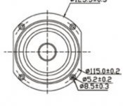
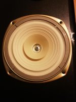
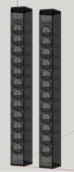
well, a plan that has been in my head for more than a decade is finally moving into reality. what: a "semi-array" of a dozen of Tangband's bamboo W4-1320 that would sit nicely next to my HT's screen.

background: at a DIY meet-up in Breda (the famous "Luisterdag") I heard a simple line array with 25 of Visaton's FR8s. impressively large sound, perfect for cinema. Somewhat later I could (rather cheaply) get a hold of 2 dozen of the W4-1320 with the 'cut-off' basket, so they could be placed closer together.

Fast forward this year... next up is to start the woodwork. I'll be getting help from a pro with a cnc router for the difficult bits.

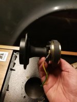
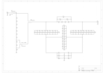
The intention is to keep it relatively simple, so no shading, just all 12 together (wired 4p-4p-4p) and then some corrections using the DSP.

Attachments

  • linearray_3D_concept.jpg
    linearray_3D_concept.jpg
    67.4 KB · Views: 213
  • W4-1320 korf.jpg
    W4-1320 korf.jpg
    24.8 KB · Views: 216
  • 12x W4 bedraden.jpg
    12x W4 bedraden.jpg
    36.6 KB · Views: 200

Did Anyone Buy And Test One Of These OPA1632 Modules?

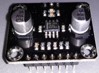
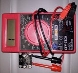
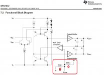
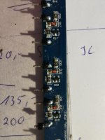
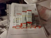
I ask since a simple multi-meter measurement shows that they don't have the 30k Ohm resistors from Vocm (common mode voltage input) and the positive and negative supplies. A real OPA1632 was measured and the 30k resistors measured 30.7k.

If you bought one of these modules (see pictures) what noise and distortion levels did you measure? Do the modules have good noise and distortion performance or should they be disposed of?

Attachments

  • OPA1632 Module Picture.jpg
    OPA1632 Module Picture.jpg
    582.8 KB · Views: 348
  • OPA1632 Module No 30k Resistor.jpg
    OPA1632 Module No 30k Resistor.jpg
    1,006.4 KB · Views: 317
  • OPA1632 Functional Block Diagram.jpg
    OPA1632 Functional Block Diagram.jpg
    93.3 KB · Views: 343

Box volume reduction with high pass filter

Hi,
I did not want to start a new thread but could not find a specific answer.
Just wanted to ask whether there is a general guideline to ascertaining how a sealed fullrange drivers recommended box volume can be reduced when you filter out the lower frequencies in order to use a subwoofer.
For example, if a box volume is given as 80 litres to yield 50Hz and you apply a filter to limit this to 100-150 Hz how far, if possible can you reduce the box volume?

Thanks

Relation between room size and subs for Tactile movie bass

Hi guys, is there any thumb rule to estimate sub size, and how many subs needed for a closed rectangular room?? This is for getting tactile bass for movies.

As far as I understand, room needs to be pressurized for Tactile bass. That needs movement of air. And the amount of air moved, depends on driver size (Sd) and Xmax.

And then, the SPL @ low frequencies may also relate to tactile bass.

So are there any formulae connecting the dots and estimate the sub size or number of subs for a given room ??

Thanks in advance,
AudfrkNaveen

Soundstream rubicon 405 input dead

Hi all, Looking for some help to repair my soundstream rubicon 405 amp.

I use the amp on my room, connected to my computer. 12v from a server psu with 1farad capp for extra smoothing. Overal worked great and sounded awesome for 1year+. Until my computer got a grouding/psu problem.... Causing 120vac (max 8mah when shorted) between "ground" of my pc and the ground of my amp. After this the amp stopped working.

long story short, the amp got 120vac(max 8mah) on the input(s).

It looks like the amp powers up normally, ~2A @12v when idle (normal as i remember). But doesn't output any sound. No dc on any in and output. rail voltage to the sub and speaker output seems OK.

All help is appreciated. I have some basic amp repairing knowledge (repaired a few output problems before) and own a basic scope. i don't own the schematic of the amp.

https://imgpile.com/images/7yGrJN.jpg

Duncyy

Internet bandwidth

Can't say as I have ever learned about the audio specs of the internet. Still waiting re FR and distortion.

But here is one data point: American Public Media - Pipe Dreams. Attached is an RTA showing organ music capabilities down to 20 Hz (I've also seen output at 16 Hz, some at 12 Hz, and some rumbling below, reminiscent of what you see from RTA from a turntable).

BTW, after a long time asking, finally figured how to do RTA while music playing. I use one channel of my DSP (Behringer DCX2496) which has unmeasurably low shortcomings of FR and distortion.

B.

Attachments

  • APM organ RTA.jpg
    APM organ RTA.jpg
    176.5 KB · Views: 161

Rear vs floor firing port.

Hi folks,

Do you think there's difference in bass perception? Of course we put the probably difference in tuning into the equation. Let's assume they get the same tuning overall.

One point to think of is the omni dispersion of the bottom firing port. But at low frequencies (40Hz tuning where my project is), rear port should be omni dispersing as well, no?

Class AB diff-amp design

Class AB FDA Design

Dear fellow audio enthusiasts,

A second year electro student here. Since a couple of months I’ve been working on this power amp idea.

Design Constraints:
  • Bridged inputs and outputs (FDA design)
  • CMRR and PSRR => 100dB
  • Single supply using 25VAC
  • In the ballpark of 100 dubs into 4 ohms (so lots of current)
  • Av=>20dB

So far I snatched up one 2k5VA 3x25VAC toroidal, two 8k5g and one 6kg heatsinks, which id like to use. Yes, absolutely overkill. Total foorprint will NOT be a limiting factor.

I will keep developing the design before I order anything less general. This community has been of great help since I first posted here. Will purchase 'Power Amplifier Design' by D Self very soon.

The fully differential design so far uses a 2n3955 monolithic dual jfet at the input and a diamond-like output stage using NJW0281/0302. The VAS is still rather basic. Altogether, it does tick all my boxes. Nevertheless I am looking for a way to give each side its own common mode feedback to account for any asymmetries.

As I'm relatively new to this game, feel free to speak out against any of my reasoning. All of your thoughts and opinions are most welcome. I am here to learn.

Cheers,

Ruben

(this is where it started🙂
Screenshot (14).png

SONY DVP-S7700 Mod to use as transport

Hi guys,
I have a Cambridge Audio 851N streamer with some mods to the power supply and DAC. The unit sounds great.
I also have an old Sony DVP-S7700. The other day I compared both. The modded CA sounds way better than the Sony. But when I used the sony as transport connected to the CA as DAC, the combo sounded excelent, being the sony a better transport.
Any idea of specific mods or upgrades for this unit to use as transport only?

Thank you
Andre Antunes

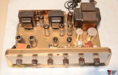
Amplifier Tube Grommes 20LJ hums when powered on

Hello people!

I have an Amplifier Tube Grommes 20LJ, condition when the power is turned on, the left channel (L) is HUM very loud, the condition lasts about 3 minutes, then it stops, the sound is also smaller.

I have repositioned the EL84 and 12AX7 tubes, i have replaced the 0.047uf cascade capacitors, and also the volume control potentiometer, but the problem is still not resolved.
What should I do, please advise me!

Thank for all.

Sorry, I'm not fluent in English!

Attachments

  • 427703-4c67c2b7-grommes_20lj_stereo_tube_amplifier.jpg
    427703-4c67c2b7-grommes_20lj_stereo_tube_amplifier.jpg
    85.8 KB · Views: 128

Ekta Grande upgrade

I would like to show one of my another projects I am currently working on. This time it is Ekta Grande upgrade. I had built exactly this pair ~22years ago according to Troels pproject and I used XT25. But soon I wanted to measure and build my own things so I decided to sold those EGs. After the years they came to new owner, living close to where I live, and I was asked to look at them, and suggest an upgrade. I listened to them first and I was a bit dissappointed, overall sound was very big, but also bass and lower midrange lacked structure and definition and trebles did not have spark. I decided to swap tweeter for TW29DN which was physically drop in replacement.
This upgarde started before I learned VituixCADv2 and the new method for measurements in individual drivers elevations. So the first crossovers were based on common mic position measurements. After some trials I started to feel that common mic method especially here is a problem. Using new method brought positive results and clearly showed the problem of common mic position method.

So big THANK YOU goes to Kimmo, and I can say that all my project that were done by VituixCAD v2 actually sound better and are better optimized.

I attached some measurements for individual drivers (horizontals 0-90deg) and also six pack and spinorama graphs.

TW29D is very good sonic match to revelators, and 5deg tilt of the baffle was exactly what was needed to align acoustic centers of the drivers, phase tracking between drivers is exceptional.

Today I managed to start working on final crossovers, all parts were glued to the boards.

Attachments

  • 12M H 0-90.png
    12M H 0-90.png
    175.2 KB · Views: 482
  • EG Kocour v1 final Spinorama.png
    EG Kocour v1 final Spinorama.png
    29.3 KB · Views: 460
  • EG Kocour v1 final.png
    EG Kocour v1 final.png
    102.9 KB · Views: 581
  • TW29DN H 0-90.png
    TW29DN H 0-90.png
    126.5 KB · Views: 463
  • 20210502_165513.jpg
    20210502_165513.jpg
    224.3 KB · Views: 486
  • 20210502_153949.jpg
    20210502_153949.jpg
    163.7 KB · Views: 447
  • 20210502_154006.jpg
    20210502_154006.jpg
    141.2 KB · Views: 319

Marantz CD-67 mk ii focus issues

I recently replaced the laser of an CD-67 mk ii with a VAM 1202 unit. It works ok but there is a strange situation that I encountered. If I play a CD that is longer than ~70 minutes, at the end of the disc, the laser does not return to the initial position close to the spindle (towards track 1). If I try to play the disk again, it will not spin the disc and will not play. If I replace the disk, I have the same situation. The only solution I have is to get into service mode and manually return the laser sled to its initial position in P00 by pressing the skip button. Is there a fix to this? The player reads all the disks if the laser is at its initial position close to the spindle.

Thanks,
Horia

New. Need help :)

I have a Soundboks 2
(The Ultimate Wireless Bluetooth Party Speaker | SOUNDBOKS)
and the horn tweeter has gone out. (Peerless Drivers - Tymphany)
I'm wondering if its possible to upgrade in the 80-100 price range?
I dont know much about speakers just the basics of wiring them.


AMPLIFIER
Merus Audio eximo® amp switching
3 x 72Wrms class D amplifier
Advanced DSP
Dynamic DC/DC Boost Converter
DRIVER UNITS
2 x 96dB 10” (Ø254mm) woofers
1 x 96dB 1” (Ø25mm) neodymium silk dome tweeter
ACOUSTICS
Effective frequency range: 40Hz - 20kHz
Psychoacoustic sound design

This is the specs of the unit. it runs on a battery but it lasts like 3 weeks for me so more power draw wouldn't be bad as long as it didn't overpower the amp and what not. Please feel free to tell me I dont know a damn thing and just buy the same thing that was in it. Thanks!

Dome tweeter Q, importance for use near Fs?

I bought a pair of ATC SCM20 Pro PSL Mk2 speakers about a year ago. They are a 20 litre 2 way studio monitor - passive.

My plan is to make them active using a dsp crossover on PC, through my RME Babyface Pro interface and out to a couple amps I already own.

The frequency I wanted to cross to the tweeter was 1.2khz, but I learned in a discussion here that the 10 inch baffle would cause a suck out starting at about 1.4khz if the tweeter was used for the upper midrange frequencies

The way I see it I have two options: raise the crossover to 1.65khz 24db/oct, or make a 15 inch wide box that's 2/3 the depth to move the suck out down to 1khz and then cross just a bit higher than planned at 1.25khz.

The closer I come to having to make the decision, the more I think the tweeter might sound better crossed at 1.65khz. It does have the excursion capability for a 1.2khz crossover point at the levels I plan to use, I'm just concerned that having it work so close to the ~935hz resonant frequency might impact sound quality. There's no Qms Qes or Qts listed anywhere for it. The tweeter is really great, but unfortunately it has almost no documentation... it's an underhung design with a 2.0B or BI, 3mm gap/2mm coil. The manual says the crossover is 2.1khz, but it's actually 1.975khz...

I took a bunch of measurements to find out how tall and wide the impedance rise is at resonance. Can this be used to find the Q? I also know that the -6db point is about 875hz.

Resistance rises to ~24 ohms at 935hz, is about 18 ohms at 1200hz, 12 ohms at 1500hz, 8 ohms at 2000hz. It seems like a wide peak - is this a good sign?

My head hurts from taking all the measurements this afternoon lol. What else can I do to determine where the lowest crossover point is which still sounds good?

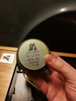
Pairs of Coral flat 8A and coral H24A

Hi, I have a pair of coral flat 8A drivers in near to mint condition and I have come to the conclusion that expensive speakers and small children do not mix.
So before someone get their greasy little fingers on them I want to unload them on someone who will enjoy them more (and raise my car renovation budget).
So, up for grabs are one pair of coral flat 8a (Brandes Zachry which where the Swedish agent back in the days).
Also one pair of tweeters, H24a.
None are soldered and more photos are available upon request.

Top dollars, or Euros would be nice but it's better if both seller and buyer are happy. So give me a price and let's see if we can work something out.

I'll post everywhere unless sanctions are in affect, however, postage could be steep

Attachments

  • IMG_20181222_134339.jpg
    IMG_20181222_134339.jpg
    331.1 KB · Views: 509
  • IMG_20181222_135040.jpg
    IMG_20181222_135040.jpg
    348.3 KB · Views: 425
  • IMG_20181222_134648.jpg
    IMG_20181222_134648.jpg
    337.2 KB · Views: 431
  • IMG_20181222_135037.jpg
    IMG_20181222_135037.jpg
    377.3 KB · Views: 432

Input RCA grounding

I see a lot of opinions on RCA jack grounding. Many OEM designs use PCB mounted jacks with a common ground. Some recommend the jack grounds remain separate until they hit the input switching. Does it REALLY matter? For context, I have 4 pairs of line level jacks mounted on an aluminum panel, and isolated from the panel. Coax runs from the jacks to a relay switching board a couple inches away. Do I wire all the jack grounds to a common point and leave the shield connected at only one end, or ground them all at the relay board? I would prefer to do this the proper way, the first time.

Diy project with tape heads

I’m planning to build a super simple and compact reel tape processor. Not really a recorder but essentially just a spinning disk with a loop of tape around it and three reel tape heads under. Spinning at a high speed im hoping to place the play and record heads close enough together to output the sound from the tape with no noticeable delay from the input.

I’m still figuring out how tape heads work but to me they seem pretty straightforward. What would I need to get the three heads to function erasing, recording and playing back from tape? How can they be controlled to perform on command?

Also, how close together could the record and playback head be placed? I’m guessing the magnetic fields will start to interfere with each other.

Glad for any insight!

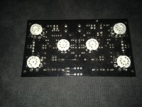
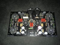
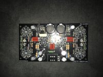
tube amp PP board for sale

Im selling totaly build,tested and ready to use STEREO tube amp board for 4x6p15p output tubes/2 per channel in pushpull and 2x 6n1p for drivers/1 per channel als phase splitter.The amp delivers up to 15 watts in pushpull configuration.I have schematic,so interested buyers contact me and I will send this.The buyer will become 4x6p15p tubes and 2x6n1p tubes nos also.If the buyer will to pay shipping cost for power transformer,he can have this also for the same price.The pover transformer is build on EI102 core,about 5kg havy and have 0-220-240v 400ma secondary and 6,3 6A secondary.The price for all stuf is 120euro plus shipping.For more info plese contact me!The amp is PP pentode mode configuration!

Attachments

  • 608E5641-E8B3-4E97-BD06-45EB08E22BB4.jpg
    608E5641-E8B3-4E97-BD06-45EB08E22BB4.jpg
    878.3 KB · Views: 735
  • 12E395D4-C672-4010-9F87-2BACF1041A4F.jpg
    12E395D4-C672-4010-9F87-2BACF1041A4F.jpg
    1.1 MB · Views: 713
  • 9F607D82-7696-4106-A28E-6C2A35D857C3.jpg
    9F607D82-7696-4106-A28E-6C2A35D857C3.jpg
    1 MB · Views: 687

Help with amp ID

A few years ago I was doing a search and came across an interesting amp, but I can't remember it now. It is a lab/instrument grade power amp, possibly made in the 60s. I do remember that it has fairly high power and according to the specs, an absurdly high amount of NFB. The schematic showed an equally ridiculous amount of circuit complexity.
The manufacturer is/was not (to me) a well known name, either from the instrumentation or audio businesses. Does it ring a bell for anyone?

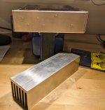
Mounting aluminum heatsinks to Hammond enclosure

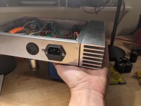
I'm looking for some advice on the best (and most straightforward) way to mount some aluminum heatsinks to a Hammond enclosure for a tube headphone amplifier project I built.

The enclosure is a 9" x 7" x 2" Hammond enclosure and the heatsinks are 2" x 7" extruded aluminum.

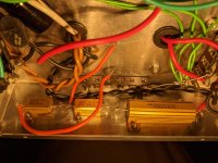
There are some power resistors mounted to the side of the enclosure with M2 screws and nuts, which protrude from the side (see pictures).

Seems like I have 3 options, would like opinions as to which is the way to go. I have a drill press and some M2 and M3 taps, but I am NOT an experienced machinist, so I'm looking to try to keep the driling and tapping complexity to a minimum.

  1. Drill some oversized holes for the screw heads to slot into the heatsinks and mount them to the side of the project enclosure with thermal epoxy. This seems like it requires the least amount of precise drilling and tapping. The downside is that they are then permanently attached and removing the power resistors later down the line becomes difficult.
  2. Drill some oversized holes for the screw heads to slot into the heatsinks and then drill and tap four (M3? M4?) holes at the corners of the heatsink and project enclosure. Use bolts to attach the heatsink to the side of the enclosure. This will require me to do a fair amount of internal disassembly so I can fit a tool inside the enclosure to actually fasten the bolts once the holes are drilled.
  3. Drill and tap the four aforementioned holes in the heatsink and enclosure AND drill and tap holes for the power resistors in the heatsink. Mount the heatsink to the side of the enclosure and then mount the power resistors to the heatsink with the screws passing through the existing holes in the enclosure.

Does this make sense? Any advice? I'm leaning toward the thermal epoxy route as it seems to be the easiest approach but I have never worked with it before, so I really don't know.

I'm concerned that my drilling and tapping skills will be put very much to the test if I go another way but I'm willing to try 😉.

Attachments

  • PXL_20210519_023653041.jpg
    PXL_20210519_023653041.jpg
    778.2 KB · Views: 266
  • PXL_20210519_023708110.jpg
    PXL_20210519_023708110.jpg
    980.6 KB · Views: 280
  • PXL_20210519_023754387.jpg
    PXL_20210519_023754387.jpg
    743.9 KB · Views: 272

Pioneer EQ-6500

Anyone have any ideas why this unit blow all of the opamps ?

And anyone know of any good replacements for the
TC40GGBP, C4570HA

Attachments

  • 3A6C4556-A03D-470B-A35C-23C3627269CA.jpg
    3A6C4556-A03D-470B-A35C-23C3627269CA.jpg
    979.5 KB · Views: 201
  • 9512A53D-C172-4297-BE73-77A900A7342C.jpg
    9512A53D-C172-4297-BE73-77A900A7342C.jpg
    996.9 KB · Views: 222
  • 38114338-F357-465C-AC0D-46A3FE0A1ADD.jpg
    38114338-F357-465C-AC0D-46A3FE0A1ADD.jpg
    982.5 KB · Views: 271
  • DBFF2085-9EE8-4142-955A-4E9C496796DE.jpg
    DBFF2085-9EE8-4142-955A-4E9C496796DE.jpg
    968.6 KB · Views: 457

Elevating heaters using a SMPS PSU for a cathode follower

Hi all, first post here!


I'm building an instrument tube buffer/DI, and the last stage is a cathode follower, so I need the heaters elevated. I'm using a 12 VDC wall wart SMPS power supply to power the whole unit, with a nixie style power supply inside the box, used for boosting the DC to get the B+ voltage.


When I try to elevate the heater voltage using a voltage divider from B+, the heaters get no voltage and no current. The 12 VDC input is referenced to ground at the input for the nixie power supply ground reference, so I'm guessing there lies the problem.


How could I get the heater elevation I need without losing the reference to 0 volts/ground that I need for the nixie power supply? Thanks in advance

Beginner Advice, Bypassing Relays in Sony TA-FB940R

Hi guys, if anyone with the patience for a 99.9% beginner can help out, as an educational experiment I'm interested in bypassing the relays in the Sony TA-FB940R amplifier. I've never done this before obviously.


I've attached a photo of the amp if anyone can tell me how to go about it in simple steps I would be very grateful!


Many thanks!


P1120817-1 — ImgBB

Interesting bit on capacitors....

Capacitors: A Field Guide to Types and Habitats by Harry Bissell


A capacitor stores a direct current electrical charge. It will pass an AC waveform and block a DC level. It consists in simple form of two parallel conductive plates separated by an insulating material called a Dielectric. The IDEAL capacitor would have infinite ability to block DC (infinite resistance), would have zero series resistance, infinite voltage handling ability, and zero series inductance, and zero temperature coefficient.

Dielectric Strength: The ability of the dielectric to withstand a certain voltage without an arc or short circuit occurring. The higher the dielectric strength, the greater the voltage the cap can be used for.

Dielectric Absorption: An effect where some of the charge stored in a capacitor does not immediately return after discharge, but slowly leaks back at a later time. Some dielectric materials have a kind of sponge effect. Even after you wring the water out of a sponge, it stays wet for some time after. Dielectric Absorption is not a desirable characteristic.

Equivalent Series Resistance (ESR): All practical capacitors have some resistance in series with them because of the lead wires, materials, etc. Low ESR is a desirable characteristic.

Self (series) Inductance: Practical capacitors have some inductance due to the construction techniques used. The minimum inductance would be the same as a single conductor (wire) the same length as the capacitor. Often this value is much higher. With an inductor in series with the cap, there is a series resonant circuit formed. The capacitor will resonate or "ring" at this frequency. Series inductance is not a desirable characteristic. The lowest series inductance caps are usually surface mount ceramic and tantalum types.

Temperature Coefficient: Practical capacitors vary somewhat with changing temperature. Some vary only a slight amount, some a great deal. The temperature coefficient (change in capacitance vs change in temperature) is not always linear.

Polarity: Capacitors that may be safely operated with only one DC polarity are called "polar" Capacitors which can be operated without regard to polarity are "non-polar". Sometimes "polar" caps are combined in special ways to allow a limited ability to cope with revering polarity are called "bipolar"

Ripple Current: The amount of AC current a capacitor can withstand and how often it can withstand it. Not all capacitors are rated for ripple current. This spec is mostly applied to capacitors that deal with AC currents, or DC caps with large AC components (often found in switch mode power supplies, and industrial equipment such as motor drives etc.).

Dielectric Materials: Most capacitors are named after the material used for their dielectric.

Air: The original dielectric material. Old time radio receivers used variable capacitors made of stacks of parallel plates, with air between them. Air is a good dielectric, which varies only slightly with humidity and airborne particles. Air dielectric caps are impractical for values beyond a few hundred picofarads because of their increasing size. Air caps are nonpolar.

Ceramic Monolithic: Ceramic materials make a good dielectric. They can be used for values from low picofarads up to usually around one microfarad. The small values are usually "monolithic", they are made of a single dielectric (usually disc shaped) with metal plated on both sides of the disk, and leads attached. They are also rated by temperature coefficient.

COG or NPO (negative-positive zero) capacitors are the most stable with temperature, but usually are available only in the picofarad range. They are larger for a given capacitance value. There are special temperature coefficient caps for compensation of circuits. These are rare.

X7R capacitors have a greater temperature coefficient, but are available in larger values. They are smaller in size than the NPO. The tempco is not linear and hard to adjust for, but the values are usually plus/minus a few percent from 0-100 degrees Celsius.

Z5U capacitors give the largest values in the smallest size package. The tempco is terrible, often falling to -50% of the value at -20 degrees and +100 degrees Celsius (relative to 25C). Use only for non-critical applications like power supply bypassing.

Ceramic Stacked: There are capacitors that are manufactured by paralleling several monolithic caps in a single package. They have larger values than a disk of similar ratings. The performance is still related to the dielectric material, they could be good or poor in tempco and voltage rating.

Ceramic (in general): For small values and high voltages ceramic caps are hard to beat. They are usually quite low in self (series) inductance, and ESR is not usually an issue. Be aware of their temperature coefficients. Some ceramic materials exhibit some piezoelectric effects, they can be electrically sensitive to vibration and shock. Most ceramics have low dielectric absorption. Ceramic caps are as a rule "nonpolar"

Mica: A very good, very stable dielectric made of the mineral Mica, with plated or deposited plates on either side (often silver, hence the name "silvered mica") These are a better performer than the ceramic caps in the NPO series. Usually mica is not practical in values larger than picofarads. Voltage ratings range into the kilovolts. Mica caps are nonpolar.

Tantalum: A dielectric capable of giving very high capacitance in a very small space. Tantalum caps are made of two constructions, Wet and Dry. Wet tantalum caps have a liquid electrolyte which causes the "dielectric" to be formed. They have been almost completely replaced by "Dry" tantalums. Dry tantalums use a spherical powered tantalum material with a dielectric coating on the outside. They are "sintered" together to form an almost solid material with very high capacitance value per unit volume. They have reasonably low self inductance and very low ESR.

Warning: Tantalum caps are RABIDLY polar. Reversing the DC polarity even for a brief period of time will cause them to heat and self-destruct. They are most common in low voltages and values below a few microfarads. High voltages and large (>5-10uF) values get very expensive. Their low ESR and self-inductance makes them perfectly suited to power supply bypass duties. Leakage current is usually very low, much better than electrolytics. They should be avoided in audio coupling (bipolar) circuits.

Electrolytic: Electrolytic caps are named for the chemicals that cause the dielectric to exist. Electrolytic caps have plates wound from a long, thin strip of aluminum foil. The dielectric is a thin (several atoms thick) coating of aluminum oxide (an excellent insulator). The aluminum oxide is formed by a chemical reaction between the electrolyte and the aluminum, in the presence of an electric field. This formed dielectric gives the capacitors some unique advantages and disadvantages. Electrolytic caps have very large capacitances per unit space, since the dielectric is so thin. The dielectric can tailored to allow voltages up to about 450 VDC, the upper limit for electrolytic caps. The disadvantages of the electrolytic come from the electrolyte, and how the dielectric is formed. The electrolyte will dry up in time, causing the capacitors to gradually decrease in capacitance. Pushing the capacitor beyond its ratings (either voltage, polarity, or ripple current) will increase the pressure in the cap until it either vents (and loses electrolyte) or explodes. The other problem is that if the electrolytic cap is not used for a long time, the dielectric becomes thinner, decreasing the voltage it can withstand. The dielectric needs an electric field (charge) in order to maintain its strength. Electrolytics that have been unused (either in storage or in unused equipment) can have their dielectric layers restored by slowly applying increasing levels of DC voltage. The procedure can take days. Electrolytics suffer from accelerated aging at elevated temperatures. A rule of thumb is that their life is cut in half for each 10 degree Celsius rise above ambient (25C). For all these reasons, electrolytics have a limited life and the user may expect to replace them at some time in the future. Excess hum on a power supply, unstable rolling picture on a monitor are often signs of an electrolytic nearing the end of its useful life. Electrolytic capacitors have a substantial amount of leakage and Dielectric Absorption. This can be a problem in timing circuits, and often limits their use. Some designs (like the 555 timer) minimize these faults by operating the capacitor at voltages where this is less of a problem. The temperature stability of electrolytics is poor and seldom specified

Polar Electrolytics: The most common variety of electrolytic capacitor. These are available in sizes from about 1uF up to fractions of a Farad. Voltage ratings exist from about 5 volts to 450 VDC. There are special varieties that have extended performance ratings, usually specified for higher temperatures, higher ripple currents, lower ESR, and enhanced reliability. All these ratings usually result in a physically larger component. There are special "sealed" electrolytics for timing applications, but they are rare.

Bi-polar Electrolytics: These are a special variety of electrolytic capacitor that are used in applications that have mixed polarity, such as audio coupling applications. Physically, they are made of two polar electrolytics connected in series at their negative terminals. They are usually twice as large as a polar electrolytic for the same voltage and capacitance value. Common uses are in "economy" grade speaker crossovers.

Supercaps (battery): These are electrolytic capacitors that are specialized for long discharge times with very low current loads. They are used for memory backup applications in place of Ni-Cad or Lithium batteries.

The major use for electrolytic capacitors is for power supply filtering and bypassing. Minor uses are for audio coupling in unipolar operation (where one terminal is always more positive than another), non-critical timing applications.

Film Capacitors: Film capacitors are the most often misunderstood members of the capacitor family. They are named after the material used as the dielectric. They come in two physical varieties, Film and Foil construction, and Metallized film construction. They are available in values from around .0005uF to several microfarads, and voltages from around 10VDC to several thousand VDC. For special applications sizes up to several thousand microfarads are available, but they are very large and very expensive. Most film caps have good to very good temperature stability, most are low in dielectric absorption. As a rule they are Non-Polar capacitors and have good AC response. Self inductance ranges from low to high, depending on the geometry of the construction. In their simplest form, they are constructed from two pieces of foil separated by a "film" of the dielectric material. This is called Film and Foil construction, and is larger and more rugged in most cases. Some film caps have a metallization layer, usually aluminum, deposited on both sides of the film. This is called Metallized Film, and is usually smaller and more expensive. Both types have similar performance.

Polyester (Mylar) Film: The most common dielectric material in use. It is low in cost and can be found in Film and Foil are Metallized varieties. Common Voltage ranges go from about 50VDC to 200VDC (up to 1000VDC) Mylar suffers from Dielectric Absorption (.20%), which makes it unsuitable for applications such as VCO timing capacitors, and Sample and Hold applications. Polyester caps do not have a linear temperature coefficient, they get progressively higher in capacitance in capacitance at elevated temperatures, and progressively lower at lower temperatures. The overall shape of the curve is similar to a horizontal letter "S". Between 25 - 85 degrees Celsius they have a rising temperature coefficient. They are useful for audio coupling, semi-critical timing circuits, tone controls, general uses. Temperature range is to 125 degrees Celsius.

Polystyrene Film: The Holy Grail of Film Capacitors, polystyrene has the most desirable electrical characteristics. With temperature coefficients as low as 30-40ppm (special) and typically less than 120ppm (standard), they have excellent linearity of temperature coefficient over the entire temperature range most equipment ever sees on this planet. Dielectric Absorption (.02%) is the lowest found in any capacitor variety. This makes the polystyrene cap the first choice for all critical timing circuits, such as VCO and VCF timings, and for all Sample / Hold circuits. Polystyrene caps cannot tolerate high temperatures (85 degrees Celsius max.), so they are not available in the metallized variety. Careless soldering can destroy them easily, and they are often poorly suited to automated production equipment. There is a persistent rumor that the only manufacturer in the world that made capacitor grade polystyrene film has ceased production. There is still stock in most values on the market, but people are well advised to save a few for top of the line circuits. There are some new polycarbonate caps which will approach the performance of polystyrene.

Polypropylene Film: Polypropylene capacitors are often used in place of polystyrene. Slightly larger than polyester (Mylar), they are superior electrically and slightly larger in size. They have a linear, negative temperature coefficient of -150ppm (and special -250ppm for compensation of coils in filter applications). If the negative temperature coefficient is desirable, they are used in place of polystyrene. Dielectric Absorption is .02%, and the temperature range is up to 105 degrees Celsius max.

Polycarbonate Film: Polycarbonate capacitors are another good choice for polystyrene replacement. Tempco and Temperature Stability are not as good as polystyrene. They are linear over a limited temperature range (25-85 degrees Celsius). Beyond this range they are not linear (similar to polyester capacitors). Polycarbonate caps withstand much higher temperatures (125 degrees Celsius max.) than polystyrene, so then can be made in Metallized Film construction. Voltage ranges are available to several thousand volts. These caps are best suited for critical coupling and timing applications, and can be used wherever Polystyrene is the preferred choice, with a slight decrease in performance. Polycarbonate caps have a moderate amount of moisture sensitivity, and Dielectric Absorption is around .08%. Polycarbonate caps are about 12% larger than polyester (Mylar).

Polysulfone Film: The same specs as polycarbonate, but with even higher temperature ratings. These are used where high temperature performance is mandated (150 degrees Celsius max.) and are rarely used for general purposes. They have a reasonably linear temperature coefficient from 25 degrees Celsius and above, but fall slightly at lower temperatures. Polysulfone caps have a slight amount of moisture sensitivity, and Dielectric Absorption is around .08%.

Teflon Film: Teflon performs as well as polystyrene in every regard, and is good for high temperatures as well. They are twice the size of a polyester (Mylar) capacitor, and high price makes their use uncommon for all but the most mission-critical applications (read aerospace). The difficulty in making anything adhere to the film makes metallization impractical. Teflon is impervious to moisture and has dielectric absorption of around .02%


Applications Notes:

Capacitor "Self Inductance"

The inductance of a practical capacitor limits the frequency range that it can be used for. At some frequency, the inductance of the capacitor will form a series resonant circuit. At this frequency the capacitor is useless as a filter. The series inductance of the capacitor also raises the impedance, limiting its ability to pass AC current. For this reason, DC power supplies often use a parallel combination of capacitors. For low frequency filtering (60-120Hz) a large value of capacitance is necessary. A polar electrolytic of several hundred to several thousand microfarads is the common choice. The large series inductance of this capacitor makes it effective only up to several hundred kilohertz. Above this, the high impedance makes it appear as "not there" to higher frequency components. To extend the frequency range, a small tantalum cap (several uF) is often added. This has much lower series inductance, so it is effective up to the low megahertz. The value can be small, because the lower frequencies are being filtered effectively by the large electrolytic. At even higher frequencies, a small ceramic (.01 to .1uF) is added in series. The same rules apply, the cap can be even smaller because the frequency of interest is even higher. Ceramic caps for decoupling use can be almost any variety (X7R, Z5U etc.) This will make a power supply filter that performs equally well at eliminating AC line hum, radio stations, microprocessor noise, etc. Remember, the filter not only stops noise from riding into your circuit, it stops your noise from reaching other circuits (yours, your neighbors' etc).

The length of traces and wire that separate individual components on a printed circuit board or a system also have "series inductance". This means that if there is a sudden, local demand for current, the voltage at that point in the circuit will drop until the current flow makes it through the current limiting inductance. For this reason, capacitors are placed very near the power terminals of active components. This limits the series inductance, so a small capacitor can act as a filter for local noise, as well as a small current reservoir. These are known as decoupling capacitors, because the make the local node act independently of (or decoupled from) the rest of the circuit. The inductance of the wiring is usually small, so the main electrolytic filter caps are still able to handle the low frequencies. At the chip level, a small tantalum or electrolytic (1-10uF) in series with a ceramic (.01-.1uF) is usually more than enough. Lack of decoupling can cause circuits to perform badly or sometimes, not to work at all. The opposite of decoupling is "coupling", meaning that there are unintended connections and interactions between circuit functions.


Coupling Capacitors:

Capacitors are often used to block different DC voltages in successive stages of audio equipment. This function requires the capacitor to have low leakage, low to moderate self inductance, and to be able to handle the AC and DC levels involved. If the DC level of one stage is ALWAYS higher than another, a polar capacitor (electrolytic) may be used. This is often the case in guitar "stomp boxes" where the input and output are ground referenced, and the circuit runs on a positive supply. If this condition can't be guaranteed, then a Bipolar electrolytic may be used. In all coupling cases, a film capacitor is a superior choice if it is practical to use one. Any film type can usually be used here. In high impedance circuits, a fairly low value coupling capacitor will give good low frequency response. If the impedance is low, however, the electrolytic (polar or bipolar) may be the only choice. Tantalum capacitors are almost always a poor choice for coupling applications. A reversal of polarity for any reason will destroy the capacitor. Electrolytics can stand a little abuse in this regard, but they should not be reverse biased for extended periods of time.


Timing Capacitors:


For all frequency sensitive applications, film caps are the best choice. Polystyrene is the best, followed by polycarbonate, and polyester (Mylar). Mylar capacitors should always be avoided in Sample/Hold and VCO applications, and used with caution in VCF circuits. If the capacitance value is very small then mica or COG/NPO ceramics may be used.


This paper is copyright 1999 by Harry R. Bissell Jr. harrybissell@prodigy.net It may be reproduced freely if my name stays on it.
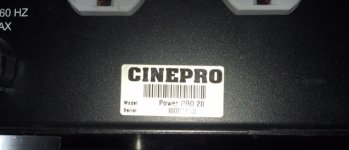
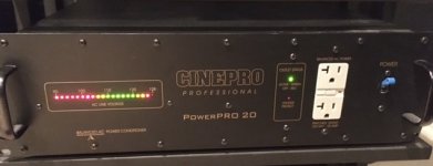
FS: Cinepro PowerPro 20 Professional AC Line Balancer, Conditioner & Surge Protector

FS: Cinepro PowerPro 20 Professional AC Line Balancer, Conditioner & Surge Protector

Selling a Cinepro Powerpro 20 Balanced power supply and power surge protector. From a pet-free and smoke-free dedicated home theater.
Prefer local pickup but can ship at buyers expense. Asking $475


Description: Line conditioner supplying balanced AC power. Output current: 20 amps (2400W at 60/120V). Voltage range: Normal, 90–130V; marginal (flashes alert), 80–90V or 130–130V AC; extreme (causes protective shutdown), below 80V or above 140V AC. Isolation (input/output): breakdown voltage, 1500V minimum; leakage current, 40µA; capacitance: 300pF maximum. Turns ratio: 1:1, windings isolated by Faraday shield. Transformer regulation: ±97% from no load to full load. Number of outlets: 12 (4 further isolated from other 8). Power consumption: 8.5W.
Dimensions: 19" W by 5.25" H by 17" D. Weight: 75 lbs.
Retail Price: $1795

Attachments

  • IMG_3596.jpg
    IMG_3596.jpg
    49.6 KB · Views: 109
  • IMG_3597.jpg
    IMG_3597.jpg
    68.2 KB · Views: 107

Life hit me hard- with an capacitors.

Disclaimer- I cant hear (in blind test) two diferent (but same same voltage and same dialectric/conctruction for example MKP vs MKP , MKT vs MKT) capacitors in speaker crossover in high dolar system. I can hear slight diferencies, but not for blind test conditions for sure.

However electronics circuits is somewhat diferent. I get upset when changed caps in amps (black gate N to nichicon KZ ( but is nothing comared to last try.. I realy get ****** off last week when did maintenance change caps (10 years) for one of my dac.

1)in dac chip digital suply replaced 2psc elna silmic II with sanyo oscon SP (both same capacity, both have cooper legs and specified for audio by manufacturers )
2)in digital receiver , ASRC upsampler section cheap SMD polymer pansonic nichicons replaced with 20psc Same Sanyo oscon SP and before regulators to panasonic FR. . Some of the caps were after lm1117 regulators. I carefull studied datasheets to replace cap for the same ESR cap @100kHz and same capacity After replacing checked for any possible oscilations.all was fine. I turned it on and left for 3 days (24hours a day) without listening to so called “burn in”

I did not expected any changes,or lets say nothing extraordinary. So the other day went to studio for work. Put some music trought this dac. Something is very diferent from the first accords. Music sounded very soft, warm and weighty ans slow with increribly low frequencies 20-30hz amplification ,just tlike someone connected a sub to system and put too much in level

Due my job duties (speaker designing) I have quite good hearing memory for some musical excerps which I play sometimes 50-80 times a week. I played them. ALl sounded very diferent from what I get used from this dac/system. I measured speakers – maybe soemthing has appened- all fine. then Ithought I will measured speakers trought this dac – made setup where analog output device was this dac. it measured within 0.13db diferencies-measurement error diferencies)

Another option for myself was explanation that was that my hearing is temprarily changed(it could vary day to day a bit depending on how many hours work on audio or how loud listening and even how much rest/sleep- its normal for us humans sometimes to have “tired” hearing cells or strange CNS brain EQ ) so to have some current time reference I put another dac – which I know many years and compared many tmes with this upgraded , this reference dac was slow, mellow, bloated,untight bass , subjekctivelly rolled of 13-16khz. so I naturally expected that sound now will be even more what I am hearing.

Howewer. this reference dac was faster ,more trasparent. Before caps upgrade they wer so diferent(I specifically selected two very diferent sonic qualityes dac’s for job duties) that I always could quess which is which- just hear bass notes tightness and 12-15khz airyness in sound diferencies.

Today I find nearly all caps I desoldered and put them back. around 15% of them were lost however. put the dac,listend, from the very first notes it seems get back to me.

I never makes special attention to parts in amps, dac, I just put quality ones. I always chooses speaker /room interaction for most important factor . and if needed - crossover corections.

If I would try to bring modified dac to normal soncis I would need to change speaker xovers by 2-2.5db in hights, and around 5-6db in 20-40hz area. that is A LOT for us, audiophiles(when mixing music trackson mixer I can hear 0.5-0.6db SPL change in sound)

I usuly read threads about caps and diferencies. I would not consider myself as passive parts sonic changes believer. I dony want to hear, and I even don’t expect. I have stict and direct wiew. But sometimes I get hit by someone who’s name is Reality. Usualy. I get small hits, but this time was knockout.


this evening I played a bit with variuos capacitors to see how its impedance changes within human hearing range. of course all caps were matched to have EXACTLY same capacistance. there is not (much) diferencies in similar caps (bigest diferencies was between Panasonics NHG cap vs Nichicon KZ cap music top range where we have last bit of main intrument tones -10khz was 0.65 ohm vs 0.3)

I am am sure someone who makes seriuos measurement swould not find big dferencies in other parameters. but for some reason they do sound diferent. and its not oscilations. Life hits hard. I envy you, caps tuners and changers- you definatelly have what to do. 🙂

Attachments

  • caps.jpg
    caps.jpg
    637.5 KB · Views: 190
  • caps3.jpg
    caps3.jpg
    403.7 KB · Views: 214
  • caps2.jpg
    caps2.jpg
    369.9 KB · Views: 185
  • caps measurements.pdf
    caps measurements.pdf
    444.8 KB · Views: 73

Eico HF 60 Monoblocks For Sale

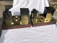
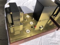
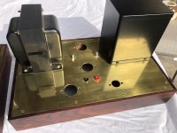
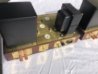
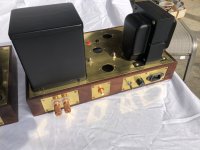
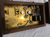
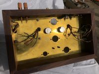
A lot of years ago I started this project to rebuild a pair of these amps but never finished them. They have been sitting for years and I do not expect to complete them. They are being sold as uncompleted.

The original chassis have been replaced by thick brass plates and rosewood bases. One amp has a first pass attempt at a power supply but no other aspects of the circuit have been built. The intention was to rebuild the units as stock as much as possible.

Tubes (including EL34 output stage tubes), sockets, capacitors, rectifiers, terminal strips, power cords, and other various components are included. The amps have the original Acro TO-330 output transformers.

I'm asking $500 for the pair. Shipping not included. These amps weigh in at about 25lbs apiece so shipping will be substantial. I'm only asking to recoup a portion of the money I have invested in these units.


Please PM me if interested,
Phil
Portland, OR

Attachments

  • IMG_0885-2.jpg
    IMG_0885-2.jpg
    842.5 KB · Views: 711
  • IMG_0886-2.jpg
    IMG_0886-2.jpg
    917.6 KB · Views: 700
  • IMG_0887-2.jpg
    IMG_0887-2.jpg
    888.7 KB · Views: 713
  • IMG_0888-2.jpg
    IMG_0888-2.jpg
    824.1 KB · Views: 686
  • IMG_0889-2.jpg
    IMG_0889-2.jpg
    819.8 KB · Views: 673
  • IMG_0890-2.jpg
    IMG_0890-2.jpg
    972.2 KB · Views: 315
  • IMG_0891-2.jpg
    IMG_0891-2.jpg
    887.9 KB · Views: 318

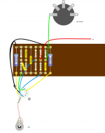
Turretboard layout for phono stage

Been drawing up the layout for this phono stage here:

RJM Audio - Tube passive phono preamplifier


I have to make a few tweaks, its missing the filter caps, etc and this is just one channel.


Before I go too far on this I thought I would share here in case there is any improvements I can make to it.
Ive found that DIY layout creator is great for this and saves me drawing over and over again from scratch on paper, but everytime I tweak it, I find something else that can be more optimized!

Attachments

  • Preamp.png
    Preamp.png
    271 KB · Views: 300

Sumo Polaris 310 bias question

Hello all, first post. I picked up a Polaris last year, and at the moment it appears to be working well in both channels. Before running it too hard with low imp loads (Maggies and Apogees), I'd like to make sure the bias is set correctly, but can't find any info on this forum or elsewhere that specifies the test points for each adjustment pot. Assuming this is a stock unit, does anyone have that info? Thanks!

Do anyone know something about that card?

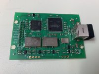
I just received I2S/HDMI card for Raspberry streamer(from Aliexpress). No documentation or the name of that card. With Volumio and Moode works only 44.1/24 and 88.2/24. May be it's improper driver or the card is broken. May be someone had expirience with that card and know her name(than I can search more). Picture of the card:
Hb8387725fb2245ea98df13f35e582041U.jpg


I appreciate your help!

Greetings,
Wojtek

Constrained layer damping adhesive

I built Jeff Bagby's Kairos in Baltic Birch. It is a great speaker, btw. But I did not follow his window bracing advice on cabinet construction and instead, I have a lot of corner braces of 3/4 x 3/4" BB sticks inside and some cross braces, making the max distance between braces <3", but the brace points are just a single point, not a beam. Above 300 it is pretty dead, the normal 400Hz BB ring is gone. But the LF is vibrating and distorting the sound. It must be some complex bending to get around all those braces, but there it is. I can feel some vibration on the sides when playing music. The audible resonance peak is at 220Hz. Below the resonance in the low bass it sounds a little cleaner.

I bought some heavy 18" true porcelain floor tiles to use as exterior stiffening or dampers. Each tile weighs 10+ pounds and rings high and long like a crystal goblet, very stiff, high Q. I intend to glue this onto the exterior surfaces of the speaker box on sides top and rear. I am hoping that the different resonant frequencies of the materials (BB and tile) will damp each other and the added stiffness of the tile will stop the LF ringing.

My question is about the adhesive to join them. Should I use PL polyurethane construction adhesive, which is super strong and rigid? Or should I use Green Glue which is soft but it's a true engineered damping material?

I have used green glue in this way before, laminating layers of MDF together on a planet10 Maiko2 where it worked very well with a couple staples at the edges to prevent sliding. Green Glue Company advised me that the BB will be able to absorb enough moisture to dry the green glue, but it might take a little longer than if it was 2 sheets of wood.

My question is should I think of this as a constrained layer damping situation to damp LF vibration, or should I look at it as a stiffening mod to raise the resonant freq of the cabinet to stop the LF vibes?
Thanks for any advice.
Rich

Linear phase EQ

As i understand it, a speaker driver is always a minimum phase system. Therefore "errors" in amplitude will always correspond to errors in phase response. If that is true then if i correct a peak using minimum phase EQ, the phase should also be corrected. The definition of correct here is flat FR and phase.

When, if ever, is it then recommended to use linear-phase gain EQ, when the goal is flat FR and phase?

Note that i am not talking about linear phase crossovers, i understand the benefit of that.

Anyone found a Ali 3-4" gem that measures well?

I'm looking for a cheap 3-4" for a FAST application in some old speaker boxes. I've looked around aliexpress, and some of the drivers appear to have good build quality. Some even have aluminium baskets even down into to 16usd range. So I'm wondering if anyone have measured some of these? I have a Fountek 2.5" alu full range but its just too small for the volume level I like. Anything in the 82-86db sensitivity range could fit with the old woofer I have. I'm not looking for perfection, just a driver for a cheap'n cheerful diy build 🙂

Valve preamp output safety concern?!

Hi,
OK, valve-based circuits require extreme caution due to high voltages when dealing with the internals.
However, I never read anything about possible safety issues "outside the case".
For example, consider any preamp design whose output is directly connected to the output stage (either a common cathode, a cathode follower, an SRPP, etc). In either case, there is only a capacitor between the output terminals and the valve.
How big is the risk if the valve or some other component fails and the high voltage goes through to the output (perhaps only as a spike due to the cap)?
For example, if the anode of a common cathode is disconnected in the socket due to some contact problem, the high voltage goes directly to the output....😕

Or, can a cathode follower conduct due to some malfunction so much that the outuput voltage is dangerously high? 😕

FS: Acoustic Elegance 15" and 18" dipole woofers

All are like-new, having been installed once, tested, and then carefully placed in storage. (Didn't up doing any larger format open baffle speakers, alas.)

Dipole15-D16 (dual 16ohm voice coils)
Quantity: 2
Price for the lot: $500
(Retail price is $359/driver)

Dipole18-D16 (dual 16ohm voice coils)
Quantity: 4
Price for the lot: $1200
(Retail price is $469/driver)

Please PM if interested. Thank you!

SONY DVP-S7700 Mod to use as transport

Hi guys,
I have a Cambridge Audio 851N streamer with some mods to the power supply and DAC. The unit sounds great.
I also have an old Sony DVP-S7700. The other day I compared both. The modded CA sounds way better than the Sony. But when I used the sony as transport connected to the CA as DAC, the combo sounded excelent, being the sony a better transport.
Any idea of specific mods or upgrades for this unit to use as transport only?

Thank you

Can't measure transconductance of 6V6

I was working on a 6V6 amp the other day, and wanted to test the tubes on my newfangled tube tester. The tester works fine, I've tested other tubes with it, but this was the first time I tried 6V6.

So, no short circuits, and emission quality seems fine, but when measuring gm I can't even dial in the meter. Everything seems *dead*.

My tester manual indicates 100V plate and 100V screen when testing these, as well as a grid voltage of -4.5V. So I tried 250/100 on plate/screen, and grid at 0V. I got some reaction, but still not enough to zero in the tester.

Ok, these tubes were bummers i thought, so I bought new ones - however, these measured just as bad. The tubes work fine in circuit, though.

I've double checked that all settings on the tube tester are ok, all pins properly configured. So I was wondering, how come I'm not able to test 6V6s? Could there be some weird fault in my tester? Or am I holding it wrong(tm)?

Any insights would be very much appreciated!

AC line noise

I just had an LG mini split air conditioner installed in my listening room.
I am now getting noise @ 4khz thru my speakers.
The AC is all inverters, compressor, and fans.
I do not have the option of using another circuit.
Is there a filter I can use to help this.
I have tried and isolation transformer, Trip Lite power conditioner and inductor based filter.
It only seems to affect my Purifi amp....
Any ideas?
Thanks for your time.

SMPS for Hi-Fi?

I know it has been done, even with audiofile grade amplifiers, but I want to know what are the special characteristics of the SMPS's for audio amps. I'm pretty much a novice with SMPS's, I only know the basics, but I have this Motorola handbook on voltage regulators (including switch mode) at home, and I thought about using a switch mode power supply for my future Quad 707, I think it would be a right place to use it, since the amp has an output rating of 240 Watts. Can anyone help with some info?

Tube modulated SMPS

Screenshot 2021-04-22 at 07.38.30.png

Screenshot 2021-04-22 at 07.46.35.png

So it is possible to modulate your SMPS directly using the voltage feedback loop 😀 This is with a simple voltage source - next is to sim with a full valve front end.

The above has a high switching frequency (300kHz) but it's certainly possible. Obviously this needs addition work for safety and for providing a wave centred around 0 (a cap could do that short term). The controller has a natural maximum current limit in the current-sensor resistor but should have some safety devices.

I'm using my isolated 48V SMPS boost controller but the same could be done with a buck converter, flyback, full/half bridge or any SMPS configuration.

This is essentially a hybrid- the back end signal does go through the PWM controller and the resulting mosfet switching is then altered to recreate the signal.

Oh and it works with 1.2V output just as well..

Screenshot 2021-04-22 at 07.53.10.png

E88CC/01 Any major difference between an E88CC?

I found a pair of these yesterday and they are both NOS and test as new at 12,600 umhos, both mullards.


At first i thought they were just E88CC, but noticed the /01 at the end which actually designates a different part number.


Seems they are a "special quality" E88CC that has low noise.


Isint that what an E88CC should be?


Sounds to me that one of these is a super dooper high quality ECC88, even moreso than the E88CC?


If its low noise, I wonder whats different, they look pretty much identical, but perhaps they have a twisted heater or something?


Either way, probably nice tubes for my phono stage, although will there be any noticeable benefit?
I still have a pair of used E88CC mullards that test near new.

A little help solving stability on a MX50X2?

As I understand it, this a clone of the MF XA-50 made by LJM. The version of the board I have is green, and was indicated somewhere as the second and improved clone by LJM.
I hope somebody can give some guidance on how I can improve the overshoot/stability on these amps. I had them for some time, and did not like the sound much (bass was good, but the rest sounded harsh..) so they were left in the scrap box. I'm hoping the issue is the overshoot/ringing, because they measure ok on distortion measurements.

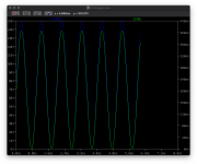
I played around with one of the boards on the scope with square input, and the things I found are:

-Massive oscillation with 0.5uF parallell to 7,2ohm load. Added a LR on the output, and there is ringing, but it is damped.

-Overshoot on the flanks with 4k square wave. Hardly visible with no load, but gets worse with lower loads and higher output voltages.

I attached some pictures with schematic and some scope shots with 1,8ohm load and no LR(worst case), 7,2ohm & LR(better), and one without load(pretty good).

So, the question is what should I try to tweak? When it comes to compensation and ringing, I'm pretty much clueless.. but maybe I can learn a little with some help here, and at the same time get a usable amp?

Baffle Step

Hello,

I've been reading this, which was interesting, especially the 0.5 speaker

http://www.diyaudio.com/forums/multi-way/38121-baffle-step-correction-circuit-how-design.html

However I have some slightly different questions

I'm currently using 2x low end drivers and a full range unit, crossed over at 500Hz with a 1st order crossover

The woofers present a 4ohm load and the mid/high an 8ohm load

If I wanted to integrate a BSC would I be looking at a seperate one for the high and low drivers?

I take it BSC comes before the crossover?

How would it affect phase as I will now have 2x inductors on one driver and and an inductor and capacitor on the other?

Off the top of my head the BSC f3 point is around 720Hz, would it make more sense to crossover higher up and just pad down the mid/high driver a bit?

Regards
Tom

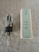
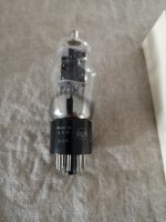
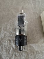
6C8G RCA NOS Military surplus singles or multiple

Well, I'm not much for glowing (phun intended) descriptions so here goes.

I have a large quantity of Swedish military issue RCA 6C8G tubes for sale.
They are all seemingly from the same batch and in unbroken individual boxes.
The one in the pictures are just opened for the sake of some photos.

A quick search says that the going price is around $20 each so I'm letting them go at $8 each.

All prices are up for discussion and if you don't like the price, just send me an offer.

If a vendor sees this and is looking to increase his or her stock then send me a message. I have enough for all (seriously)

Please note that they are located in Sweden and shipping to the EU and US is approximately the same at:
$15 for up to 1kg traceable
$13 for up to 250g traceable
$4-8 for 1-10 tubes untraceable

Attachments

  • IMG_20200512_100950_resized_20200512_112912672.jpg
    IMG_20200512_100950_resized_20200512_112912672.jpg
    911.7 KB · Views: 309
  • IMG_20200512_101028_resized_20200512_112912048.jpg
    IMG_20200512_101028_resized_20200512_112912048.jpg
    728 KB · Views: 275
  • IMG_20200512_101016_resized_20200512_112912377.jpg
    IMG_20200512_101016_resized_20200512_112912377.jpg
    820.6 KB · Views: 284

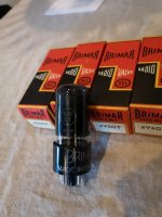
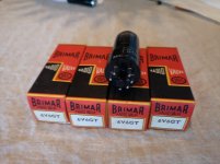
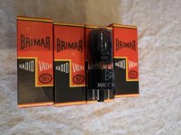
FS 4x black Brimar 6v6gt NOS NiB

These are up for sale.

NOS, in original boxes, only opened for inspection.
Never used or otherwise connected to anything.

As long as DHL or swedish postal service can deliver it I will ship it to you.

I had an offer for roughly $250 ex shipping but had some problem with DHL.
But as always, all prices are negotiable.
If it is to steep, make a counter offer.

Attachments

  • IMG_20200512_201536.jpg
    IMG_20200512_201536.jpg
    388.7 KB · Views: 252
  • IMG_20200512_201450.jpg
    IMG_20200512_201450.jpg
    608.8 KB · Views: 254
  • IMG_20200512_201441.jpg
    IMG_20200512_201441.jpg
    787.4 KB · Views: 273

Lots of audio and radio tubes

I took over a collection of tubes from an old collector/repairguy who recently passed away.
These are the tubes he kept in original boxes and since used ones lay mixed together in larger boxes I can only assume that these are unused. Many of them are still paper wrapped.

Prices are from completed Ebay listings minus around 20% but if you don't like the prices, send me an offer.

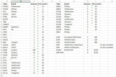
See attached list for tubes and prices.

"Surplus" means RCA and KEN-RAD

I ship to the US and Europe for around £5 untraced and £12 traced.
Depending on the no of tubes of course.

Feel free to send me a message if you have questions.
Or even better, email at ki1ohke at hotmail dot com
Then I can send photos from my phone as well.

Attachments

  • Boxed Tubes.jpg
    Boxed Tubes.jpg
    170.8 KB · Views: 475

hybrid esl without resonance damping screens: possible?

Hi, I have been troubled by un / under damped fundamental resonances for a long time. My latest stats, model #4, have printing mesh screens on the rear side to tame the fundamental resonance which is currently at 19 Hz. I will publish my new measuring results soon as I tried a new screen with higher rayle / resistance. The problem is, in my opinion, that a better damping results in poorer mid / high frequency quality.

As the sensitivity of my bigger panels are limited as well, I decided to build a new model, #5, of which I will start a new topic here in future. But I would like to try to build the electrostatic panel without damping screen. It measures 40 x 150 cm outer dimensions, diaphragm dimensions are 23 x 130 cm. I built a pair of ripole woofers similar to the ones Charlie (Jazzman) built.

My question: can one build undamped esl panels, combining them with electromagnetic (sub)woofers without the subwoofers exciting the esl panel resonance(s)?

The crossover frequency will be 80 to 100 Hz, @48 dB/oct (DSP), and the esl panel resonance will be between 40 and 50 I estimate.

NOS Telefunken EL84

Hi, I have a bunch of vintage EL84 from Telefunken, all tested with Roetester and matched in pairs.
Complete with nice and original boxes and all are of course genuine.
I'll supply the test results as well.
I have 6 brand new pairs in total and also a few used Telefunken and Philips.

I'm asking only £100 per matched pair ex shipping from Sweden.
Shipping is £5 uninsured and untraceable.
£12 insured and traceable.

Reproduction costs around £60 a pair so this should be a fair price.

Attachments

  • P_20200827_065306.jpg
    P_20200827_065306.jpg
    727.3 KB · Views: 349

PCB for Samuel Groner's low distortion passive notch filter

This group buy is for PCBs for a fixed frequency passive notch filter designed by Samuel Groner for very high resolution distortion measurements.

BTW, I have designed a little PCB for a fixed frequency passive notch filter for very high resolution distortion measurements. The exact notch frequency is tuned to a fixed value during construction by iteratively adding selected resistor values. The easily implemented frequency range is about 10 Hz to 20 kHz (I've gone up to 100 kHz, but the notch depth degraded presumably because of strays) and set by chosing suitable capacitor values. As an additional feature it includes a selectable 10/20 dB input attenuator. This allows measurement verification at lower notch filter operating levels to gain further confidence in the measurement result.

This design is not as easily used as implementations which include notch filter bootstrapping (to avoid significant attenuation of the 2nd and 3rd harmonic; for my design you'll need to correct for frequency response) and center frequency trimming (for my design you'll need to adjust the oscillator frequency if it doesn't match the notch frequency). However, it avoids the subtle and difficult to quantify distortion contributions from the bootstrapping opamps and potentiometers and is thus more suitable when working below -120 dB.

I'm still evaluating this design with respect to its distortion contribution, but it looks like it is below -130 dB.

The schematic, together with construction and application notes, can be found on Mr. Groner's web site. A copy of the schematic is also attached below.
  • Resistors are metal/thin film MiniMELF (R11-R14, R18 and R19 0.1%, others 1%).
  • Caps are ceramic C0G, 1206, 1%, 50 V or higher.
  • Shown capacitor values are for 10 Hz. 10 nF gives 100 Hz etc.
  • R15-R17 and R20-R23 are selected to tune the exact notch frequency.
The PCB is 80x55.5mm, designed to fit into e.g. Hammond 1457C801E, and hosts a notch filter for one fixed frequency.

In terms of the price, it is $10 apiece plus the cost of USPS First Class shipping and an envelope (together, about $4 for the US and $15 elsewhere).

This GB has been agreed upon with Mr. Groner.

If you're interested, please post your name and the quantity of the PCBs desired.

Attachments

  • notch_filter_r1.png
    notch_filter_r1.png
    314.6 KB · Views: 1,419

B1 build

Hello,
I’m currently building an F6 and am already looking for options for a preamp that is a good match for the f6. The B1 buffer preamp looks like what I may choose but I wanted to ask here for opinions and options. I realize the original B1 circuit has been around for awhile so maybe something else has come along.
Options please,
Thanks
I should add that I do have a preamp from Bottlehead ( the Extended Foreplay 3) that I intend to use initially.

Harmon Kardon TA224 "Stereo Recital"

Hello everybody,

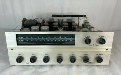
This is my first post on DIYaudio, although I have been reading the post for many years. Today I bought a Harmon Kardon TA 224, labeled "Stereo Recital". It's an integrated tube amp with a AM FM tuner. I haven't seen it in person yet, but it was made in the USA, seems to have some decent iron in it. It's suppose to power up, the front panel looks good. I'm excited with the prospect of restoring it and finding out what it sounds like.
I'm trying to find out when this receiver was introduced and if anyone here has any experience with this HK model that they would like to share, it seems there is very little information out on the web about this one, I wasn't able to find any links on DIYaudio when searching for "Harmon Kardon TA224", it seems that it's somewhat an unknown.

Lou

Currently listening to a HK Citation V, JBL L65's, Apt/Holman Pre-amp, Technics MkIII, Logitech DAC

Attachments

  • HK TA224 front.jpg
    HK TA224 front.jpg
    247.7 KB · Views: 365
  • HK TA224 overhead.jpg
    HK TA224 overhead.jpg
    177.4 KB · Views: 326
  • HK TA224 overhead 2.jpg
    HK TA224 overhead 2.jpg
    289.4 KB · Views: 312

noob question which cables will I need for v200 amp > rokit krk5?

Hi all sorry for the noob question

Needed a new headphone amp and based on the excellent review thread here bought the iamd v200 which has been frankly magnificent for headphones so far.

Now I want to connect my KRK 5 to it, but it looks like it only supports speaker cable, and the KRK 5 are active so they only have RCA/TRS and the usual.

What's the best way to connect each KRK speaker to the IAM amp? I have three options, RCA unbalanced, or TRS balanced, or XLR balanced.

I attached i/o photos for convenience

Attachments

  • -[1].jpg
    -[1].jpg
    56.7 KB · Views: 92
  • krkrear-qxhCXz0G06Er7nGZ39tts1xi05QAB559[1].jpg
    krkrear-qxhCXz0G06Er7nGZ39tts1xi05QAB559[1].jpg
    84.2 KB · Views: 94

Can you review my system technical specs

Hey guys, could you review my system technical specification for DJ?
Includes:
(X1) Powered Subwoofer of 18 Inches, 134 dB Peak, 30Hz-102Hz at +/-10 dB (or 35Hz-87Hz at +/-3dB)
(X2) Two Way Cabinets, 10 inch woofer and 1.4 inch tweeter, crossover in 2.5kHz. Each plays 129dB peak, 55Hz-20kHz at +/-10dB.

Why I got a 18 sub:
I wanted to buy two subwoofers to play in stereo subwoofers but I had the money to buy only one. I bought a good one though, JBL PRX 818XLF.

Why I got a pair of 10 inches speaker:
Someone recommended me to buy 12 inches speakers to play with the 18 inch subwoofer, but I was afraid of lose the mid clarity due to the large cone of the 12 inch speaker have difficulty to play those mids frequencies.
The smaller cone, more mids, less bass.

Guys, I got a little problem.
I was connecting these 1p inch speakers from the subwoofer built in HiPass 80Hz outputs, which is the recommended Crossover for this subwoofer. But unfortunately, my 10 inch speakers has a recommended LowPass of 120Hertz Built In also.
I dont know which one I should use!

Should I play with subwoofer HiPass 80Hertz crossover or play with my speakers LowPass 120Hertz cross over?

I've tested both and I don't know which one is better.
If I could apply a 100Hz cross Over would be a intermediate between 80Hz and 120Hz but I dont have this choice due to limitations of my equipment resources.
Thank you so much!

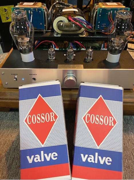
Cossor Blackplate 300B --> work horse

COSSOR BLACK PLATE 300B (MADE by LINLAI)


Henry is the first customer to buy COssor Blackplate
Here is his comment:

Victor,

It has been a while since we last spoke.. but the Cossor Blackplate 300B I bought from you last year have surpassed 4,000 hours!!! By far the longest working 300B I have used!

Absolutely! That was plan, figured they would have only lasted 1800 maybe even 2000 hours.. But no.. here I am almost a year later still using the same 300B. I'll be taking readings with my Cardmatic compare to day one too. They still sound very decent!

But they fact that the heater has not failed like in other modern 300B.. that is beyond incredible!

What ever they are doing they need to to keep doing that!
.......

Thanks
Henry...


Full-Range Synergy Kit Questions

So for those that are seriously thinking about building your own DIY full-range Multiple Entry Horn (MEH), also called "Synergies™", some questions:

1) What common compression driver(s) and woofers would you most want to use (brand and model) in a kit?

Remember that the compression drivers must cover a wide operating band, so 2" compression drivers are typically simpler and also in the $140-$240(US) range. These will replace midrange drivers that are difficult to integrate and are problematic when it comes to finding real estate on the horn throat area between the compression driver and the woofers. That way you avoid more than 2/3rds of the problems encountered with multiple entry horns.

Woofers need to have medium Qts values (0.6, etc.) and relatively low Fs to work well as horn-loaded woofers.

2) What is the lowest crossing frequency (i.e., "fc") that you would want out of the loudspeaker?

Typical values are in the range of 100, 50, and 30 Hz for "full-range" horns.

3) What maximum size would you be willing to build/buy for your listening environment?

The size of a Klipsch La Scala? Smaller? How small? How much low end would you be willing to give up to have a small size? Are these only going to be stereo pairs? Three across the front? Or surrounds, too? Elevation (Atmos)?

4) How much would you realistically be willing to spend per loudspeaker to make them from a kit?

5) Would you be willing to use an active crossover instead of passive?
Projects by fanatics, for fanatics
Get answers and advice for everyone wanting to learn the art of audio.
Join the Community
507,743
Members
7,886,330
Messages

Filter

Forum Statistics

Threads
406,147
Messages
7,886,330
Members
507,743
Latest member
Fitodiod