a discrete LM833 ?

I found a schematic for a LM833 on the data sheet and I labeled all the components. I have been looking for the schematic of an op-amp to try to build out of discrete transistors to see how that works, especially because it might be useful to try to build it from 2N5551/2N5401 to increase the voltage range of the amplifier. I would have to decrease the quiescent currents so this might reduce the slew rate however, but it might still be interesting to try.


First of all, does this look like a good design to start with? I looked at the NE5532 schematic but it required multiple emitter and multiple collector transistors which I think are going to be hard to get, or match parts to provide work-alikes.


Is the P MOSFET or P JFET (Q2) I think is there to ensure that Q1 turns on when the chip is powered on?


It looks like C2 is a compensation capacitor for unity gain stability perhaps?


Is it possible to get performance from a discrete design that is comparable to the IC version, or are the matched components in the manufactured chip required to get low values of offset and distortion?

Attachments

  • lm833-diagram.png
    lm833-diagram.png
    44.6 KB · Views: 627

Opinions on my layout for this volume/gain circuit

I've built the (LJM) L12-2 amps, sounds fantastic, however I want to incorporate Lt and Rt volume/gain control. There is a lot of info in these forums and I found one I like and think will work. Its from Parts Express. Buffered Volume Control -

Techtalk Speaker Building, Audio, Video Discussion Forum
.

I'm no engineer but I do know that layout of traces and components on a PCB board is important.

I need some opinions if the layout I did is going to work before I burn the PCB.

Thanks much🙂

Attachments

  • Preamp.jpg
    Preamp.jpg
    174.2 KB · Views: 112

10" mid in WMTM baffleless speaker

Hi guys,


I am planning an open baffle speaker with a 15" BMS woofer, a 18s nmba520 10" mid and the 18s nds1095 CD with XT1086 horn.


The Baffle for the 15" will be a U-frame to be determined. The one for the mid is supposed to be as small as possible.


I wondered now if the speaker could potentially profit from a second mid driver in a MTM configuration. With a crossover at 1400hz a tweeter woofer distance of 23cm is advised which seems doable with the 10" and size of the horn. I am not too familiar with MTM designs and well, speaker design in general so is that a stupid idea? What are your thoughts?


I ordered the parts a little prematurely a few weeks ago so that is nothing to be discussed. I could only order a second nmba520.


Thanks!

Engl 530 mods

I have a Engl 530 preamp.
It's a 4 channel guitar preamp with 2 ecc88 tubes inside.
The first 2 channels have a "fender type" eq before the main distortion tubes, the other channels have a "marshall type" eq after the distortion tubes.

What I don't like is the sound of the high gain stage. And imo it can be made a lot more versatile.

So what I've done is changed the high gain stage. It was a normal anode follower with 330k anode resistor and 3k3 kathode resistor bypassed with a 20uF cap. It's the 3th stage in the schematic (the schematic is only a very rough guide to what it really is!) I've changed it to a 120k anode resistor and a 1k kathode resistor bypassed with a 20uF cap. This is a place where you can experiment a lot, so it suites your taste.

An other thing I've done is use both eq's for the higher gain channels. This makes it way way more flexible in sound sculpting for distortion sounds.
It's just a wire from the output of the first eq to the gain pot of the higher gain channels, and I had to remove a 100k resistor between the first and second stage that is not in the schematic.

To do: Set the marshall type eq behind the cleaner channels. This is more difficult to do as there are 2 relay's and 2 circuitboards for this.


Any suggestions?


P.s. somehow I couldn't add the schematic and picture of the mods I've done, but it's not difficult to figure out (even I could do it).

Newb, Check my math for OPT WR ?

The attached shows what I believe is WR for my OPT.
I ran my variac at 60hz into the primary until I measured 1v on the secondary.
On the 8Ω terminal I had 19.14 volts on the plate side
For giggles, on the 4Ω terminal I took two measurements... Im unsure of which way was the right way. As they are darn close I cant even guess at the correct method. The 1st method for the 4 ohm tap, I kept the same 19.14 on the primary, and measured the 4Ω at .718V. Then 2nd, I ran the variac up until the 4 ohm had 1V, on the primary was 25.8

The attached is a screen shot of my excel sheet...
Does it look like Im on the right track ?

Which reflected impedance would be the one someone would design around ?
(8Ω @ 2560 or 4Ω @ 2842 ??)

Attachments

  • MS-300B OPT data.JPG
    MS-300B OPT data.JPG
    59.8 KB · Views: 135

FS: The last Antennacraft FM6 FM antenna on Earth?

Just ran across a new old stock Antennacraft FM6 rooftop FM antenna in my garage. Still sealed in the box. These were discontinued some time ago.

I forgot I bought one years ago as a backup to the one on my roof. Never needed it and I think someone else should use this. If you're interested please send me a message. Thank you.

(I'm in Chicago if anyone local is interested)

(My install can be viewed at Antennacraft FM6 )

question of VI limiter

I have been using a VI limiter in my amplifier design and it seems to cause more trouble than its worth. The problem is that I haven't found a good alternative that is simple enough to be foolproof to implement.


The problem is, the VI limiter kicks in where there is even a brief spike on the input that drives the input to the rail. The VI limiter transistor, or some other transistor, will usually immediately exceed SOA and be damaged with the result being the fuse is blown on the amplifier. This seems to be because the VAS provides more current than the VI limiter transistor can handle. Limiting the VAS current (even temporarily) seems to have a negative effect on distortion. Ultimately, it seems like the feedback tends to force the current in some part of the amplifier to become high to compensate for the limiting of the output current by the VI limiter.


Other solutions seem less than satisfactory. Speaker fuses can be nonlinear, and speaker relay contacts can be welded shut or become pitted and cause problems. I don't care if the amplifier shuts off, only that it saves the speaker and hopefully itself.


It seems to me that any solution must simultaneously shut down the whole amplifier to prevent the feedback from going to an extreme level in some part of the amplifier. The solution I thought of was to perhaps to put MOSFET switches in the power rails of the amplifier to shut the power down quickly in the even of an output short circuit for example.


I have read about the other solutions in Bob Cordell's amplifier book. For example, flying catch diodes don't seem to kick in except at very high currents, and he also suggests using a TRIAC to shut down the base bias circuit if there is an overcurrent. Has anyone tried these? In simulation, the TRIAC seems to have similar issues where the VAS will deliver too much current to it and could be damaged.

Balanced F5 (F5X) Questions

Hi, everyone.

Preemptive apology for the Wall o' Text.

So, I have the transformers and heatsinks left over from a pair of AX100s I had built years and years ago sitting around. I had retired the AX100s and built a whole surround system of 40w Mini UP Amps and I had always planned to recycle the AX100 hardware into 100w UPs to run my main L and R speakers, but just never got around to it. Well. . . I'm finally getting around to it.

I had decided on the UP amps earlier because I had built a bunch of UGS preamps and understood the circuit really well. I've been out of the loop for several years, so I've been cruising the forums to see what's new and have come to the realization that the balanced F5 circuit is really just a more elegant version of a UGS Power amp. So, I have decided to change it up and build two Balanced F5 Turbos (V1) with 3 pairs of output Mosfets per side.

So here's where I need some help: The threads for the F5 and F5x have gotten HUUUUUUUUGE!!! I've been trying this past week to skim through them and search for information, but I've been getting frustrated. What's worse is that if someone had posted a link to another post in the thread (i.e. "There is a bunch of info in this post (link)") it just takes you to the first page. So, I'd like run through a few questions and I hope you all can steer me to the info I'm looking for.

My starting point is the schematic in post #4 of "the F5X -EUVL Builder's Thread". Is this still the "standard" version? Any clever updates I'm missing out on?

Next, If I believe correctly, the F5X circuit in question is NOT a true "X" circuit (in the SuSy sense). There are a few tidbits I found in that it may be possible to make a true balanced SuSy F5 amp. Most notably, in the F5 thread Nelson says in post #1255: ".. The most obvious is to simply take the 10 ohm resistors to ground and connect them to each other instead. The other is to make an X circuit out of it."

There are a few follow up posts with people getting excited about this prospect and the Nelson's wording seems like he's begging someone to follow up on it, but I haven't found any other discussions on the topic. It would be trivial to not use the so-called "current feedback" and instead run standard voltage feedback to the opposite inputs. Is this what he was talking about? The circuit would be "X", but it really wouldn't be "F5" anymore. I'd love to revisit this topic if there is still a puzzle to be solved. I'll probably try it both ways just to experiment. Has anyone else tried it with voltage feedback to the inputs?

Moving on, The EUVL schematic forgoes both the current limiting and thermal compensation. I'm not to worried at all about leaving out the current limiting. What I've found suggests that while the thermal compensation does speed up the warm up time and provide better absolute offset stability, its benefits don't out weigh the loss in sound quality. Trying to find some ballpark numbers: How much difference in time between warm up are we talking? 15min? 5hrs? If there is a significant time difference, I'm thinking about making it switchable, so after the amp warms up, I'll just switch the thermistors out ouf the circuit. What's the offset stability like with and without? Are we in the mV range or multiple Volts range (or somewhere in between)?

What are the details about the 5ohm Rs added at the input p-jfets sources? I understand they are for better current matching with the n-jfets. But, I haven't found a detailed discription about them. Why 5ohm? Why haven't I seen them used before?

In my UP amps, the front end rails are regulated at +/-30V with 22V unreg to the output devices, any reason not to run the first stage regulated on the F5X? I still have some regulator boards so it will be easy to do. I'm planning on cascoding the jfets and raising the value of the drain resistors to compensate for the higher rail (probably 35V ish). The unreg power rails should be close to 26V (19V secondaries). I figure, get as much voltage from the front as I can. I know the F5x is decently quiet as is, so the regulation is overkill for noise, but, hey, why not? Any pitfalls I'm not seeing here?

Again, sorry for the huge post. Hope I didn't bore everyone. If you know where the answers are, feel free to just post a link to the appropriate posts. Like I said earlier, it's practically impossible to go through entire threads; the F5 thread is 1600+ PAGES long!!

-Scott

Satyrian's First pp amp project .

Im starting up a new project building my first push pull amplifier.
The chematics i have found and wanted to start with for this project is : DIY Push-Pull (PP) 6V6 / 6V6GT Tube Amplifier Schematic


The schematic is a edited version of a dynaco A 410 amp schematic.

Edit: after reading this post 6V6 pp design comparison i kinda walked away from this schematic,

so if anyone have a good schematic suggestion or a schematic they want to share. go for it.


the tubes i have are: 12ax7,12at7,12au7,807, 6v6g, 6v6gt, 6v6gta, 6j5gt, 6sj7gt, 6sn7gt, el84, 6aq8, 6cw5


power transformers i have: Hammond 372JX . unknown 250-0-250v transformer,

Output transformers i have: Hammond 1608A , uknown chinese brand, came from a amp that run kt88 in push pull without ul tap. (williamson design(ish)

Simulation Akabak

Hi everyone,


I did a compound simulation in Hornresp. I'm not able to do this in Akabak, I have tried several times but without success. I spent more than tens hours, not in my capacity.
I'm not sure about my simulation and I'm stuck today.
Could either of you do the simulation in Akabak ?
The speaker is the B&C 21DS115
Box size : 104 x 75 x 65


Regards,


Axel

Attachments

  • MHB-54.jpg
    MHB-54.jpg
    128.6 KB · Views: 172
  • Hornresp-43.5.jpg
    Hornresp-43.5.jpg
    61.8 KB · Views: 159

Reverberation Unit Installation

I recently unearthed a Pioneer SR-202 reverberation unit and would like to incorporate it into my system. My system consists of a CD player, a preamp, an equalizer, a crossover, and a power amp. Input will largely be bluetooth from my computer.

Here's what the Pioneer manual says about hooking the unit up:

Connect the tape recording terminals of the amplifier or receiver to the REVERBERATION AMPLIFIER INPUT terminals.

Connect the tape recording terminals of the amplifier or receiver to the REVERBERATION AMPLIFIER OUTPUT terminals.

Problem is, all my preamp has are (left to right) Phono, aux three through one, and Line (all right and left).

I have read that the reverb signal is mono, and that one can just run it in right and out left (or vice versa). I really don't have enough info to figure anything out. Any help out there?

What are the cathode and anode materials used in valves?

First post!

I’m interested in knowing about the actual materials used in construction of valves.

I know that the cathode is a metal with a special low workfunction coating which significantly increases the rate at which electrons can escape the surface for a give temperature.

What is an example of a “modern” coating material used for cathodes?

Similarly, does the anode require any special surface modifications to accept electrons?

Arcam FMJ A22 Flashing Red Power LED

Hello,

After years of faultless service my A22 has recently started to shut itself down after 15-20 minutes of use at normal volumes. The display also seems to be a bit unreliable occasionally not coming on at all on power up and occasionally going off while the amp is running. Is there any chance that this is related to the protection circuit kicking in?

I've taken the lid off and can't see anything that looks particularly suspicious - no bloated caps, no signs of overheating etc. Is this something that I could debug by probing the Z9 device or is it likely to be a lost cause?

Also, Arcam's website now says that they are "unable to engage with Arcam owners directly when it comes to servicing equipment" which is a shame as they are just up the road and I previously found them very helpful. Has anyone tried to deal directly with Arcam recently? I'd contact my dealer for help but sadly they closed a couple of years ago...

Thanks for any advice!

Looking for a preamp kit

I'm on the hunt for a preamp kit.

My needs are simple: I need a few inputs, volume control for the main output, and a fixed-volume "record out". I'll need a phono pre, but if it's not incorporated in the the preamp I can always use a standalone unit like the Muffsy.

Tube, solid state, or passive. Doesn't really matter, but I think I'd prefer solid state or passive.

It's OK if it isn't sold as a kit with parts: PCB/Gerbers + BOM will do the trick.

So far I've found two that seem to fit the bill:

The Akitika PR102 has everything I need, but I'm not crazy about the looks. Looks are easy enough to change, however.

The Glasshouse Passive Preamp No.1 also has everything I need, and I like the look, but it seems to be possible only to build it with a stepped volume attenuator, and I much prefer a potentiometer volume control, as stepped attenuators never give me the precision volume levels I want. I've written them to ask if it can be built with a pot, but they've not replied.

So I'm poking around for other options. Any recommendations?

Looking for Macintosh C24 Volume Pot Recommendations

Hi folks,

The volume pot on my Macintosh C24 is failing, so I'd love recommendations for where to obtain a reputable new, NOS or healthy used one. I've gone through the Deoxit routine.

I see a few new options on eBay, but have no idea how reputable those are and Audio Classics doesn't have anything in stock.

I apologize if this is redundant relative to previous posts, but I tried a few quick searches here with no luck based on thread subject lines (and I'm a rank newbee, so maybe searching the wrong forum?).

Thanks for any suggestions!

Alchemist Forseti ADP20 schematics

Hi,
I have decided to try to decipher the Alchemist Forseti Power Amp ADP20, from some photos found in the net 😉. Below I attatch the schematic I have made. I would appreciate any help in finding any mistakes. Originally it worked in class AB it had 153W in to 8ohms, i don't know if the power voltage 36V that i had counted is OK. So I need your help for this project 🙂.

Attachments

  • forseti.jpg
    forseti.jpg
    232.9 KB · Views: 1,366

Do wheels of PA cart need shock aborber?

I have worked on a cart made of a wooden tablet and 4 wheels to carry my subwoofer, but I have some worries I would like to ask you guys:

I noticed some shake and I am worried about it damage the internal components of the sub. It shakes when I carry the cart through a stone non leveled terrain.

Should I add shock aborbers to the cart or if I go slowly through the stones is Ok?

The wheels are huge 15 centimeters of diameter each.

Later I can share here a picture of the cart.

A and R Arcam A60 help sought

Hi,
Looking for help diagnosing problems with an A and R A60. This amp arrived with quite a few burntout resistors and transistors. In essence it seems new transistors had been installed without insulating pads so as well as taking out the transistors and drivers it had taken out all the over-current limiting circuit. I recapped it and installed new transistors Q13-21 and the righthand equivalents. Also any resitor with signs of scorching or out of tolerance was replaced so around 80% of total. However, I did not install the over-current limiting components Diodes D1 and D2, Transistors Q16 and Q17, Resistors R54,R55,R56,R57,R58 and R59.

Basically I wanted to get the amp up and running first before re-installing those components.

On switching on, the Dc offset on the output is within tolerance at around 30mv per channel. However, the quiescent current is way too high on both channels. On one channel the minimum adjustment gives me around 112ma across R63, 64. The other channel measures 1.5v across R163,164. Most of the other voltages are as per the attached schematic except on the worse channel the emitted /base voltages on Q18, 19 ar around 1v.
David

Any help to help me diagnose the problem is very much appreciated!

Attachments

UGLY Looking Amp! - but good working

😎 More pictures of Normal Ugly (but good) AMPS! 😎
PLEASE post a picture of your NOT so well looking AMP!


---------------------------------------------------------
Of natural causes, it is only the most "beautiful amps"
that get pictures posted. They are running the SHOW.
But surely they are only "the tip of an iceberg".

95% of All Good Great Sounding DIY-amps are REALLY Ugly.
Made up of materials recycled from scrapyards.
And simple chassis of thin, 1-2 mm Aluminium.
No fancy LEDs or Knobs.
---------------------------------------------------------

I want to see more of these AMPS.
More of the DIY everyday reality. 🙄

I could bet on that the amps that SOUNDS best
built by diyaudio members, are not very exceptionally looking....

/halo - has only built crappy looking amps
(Moderators: 😉 Any GOOD loooking Amp in this thread should go directly to TEXAS! 😉 )

What beats the Dayton TCP 115 in a 4L to 5L box?

The Dayton TCP 115 (Dayton Audio TCP115-4 4" Treated Paper Cone Midbass Woofer 4 Ohm) is a driver which has an F3 of 48Hz and a maximun SPL of 95db in a 4.4L cabinet.
When paired with a decent tweeter and crossed over around 2500Hz it produces what to my ears is the best overall sound I have heard from such a small cabinet. The Duane Brown Dayton 4, which uses this driver and the Dayton ND16 tweeter, has been built by several U.S. DIYers and has been given uniformly positive reviews.
So, what I'm wondering is if this more international group is aware of any two way speaker of 4.5L or less which sounds good and can equal the F3 and maximum SPL of this dirt cheap little driver? Note that with an additional couple of liters of cabinet volume, there are drivers that can best it, but that I am setting 5L gross volume as the biggest I want to build.
Of drivers I've owned and tested, the HiVi B4 N, the Dayton ND105, the Techtonic Elements BM65C, the Tang Band W4 1720 and Aura NS 3 are contenders, but can't beat it.
I love small speakers and I love small speakers that amaze with low F3s and high SPL. It just seems to me that there must be a way to better the tiny Dayton 4's giant killer performance. Then again, maybe not without going to 6L or more.
Your experience and inputs would be greatly appreciated.
Best,
Jay

LOEWE OPTA Electrostatic tweeters

I am looking at building speakers with electrostatic tweeters and I like these I found on ebay.

PAIR 3" LOEWE OPTA ELECTRO STATIC TWEETERS from Germany
vintage PAIR 3" LOEWE OPTA ELECTRO STATIC TWEETERS from germany | eBay

However I don't know anything about these speakers and there is no information in the listing.

Does anyone know what the voltage on the stators would be? I am also looking to use field coil woofers with these (Philcos) which use a voltage around 100VDC. What are the chances that I could use the field coil voltage on the stators?

Aleph J, F5T or something else?

After much reading about the Aleph J, and the sound image it will provide, I'm drawn to this amp. The only issue I have, is that my speakers is a Gemme Audio Tanto clone, so 4 ohm. And from what I can understand, the Aleph J will have some distortion at 4 ohm.

Which is why I've been reading about F5T, which should have no problems running these speakers, but I would rather prefer a single-ended amp.

What do you think, Aleph J or F5T, or something else for the next build?

Thank you.

EQ/Filter gradual bypass with potentiometer

I have a parametric EQ after a preamp and I need to bypass its effect gradually, in such a way that I can control how much of the source line is affected by the EQ and how much runs directly to the output unaffected.

I tried the most basic workaround (no intention to offend anybody): a 10K pot to the EQ output (pot1), the source line (pot3) and the mixed output (wiper), like in the drawing below. It didn't work, lines attenuate as they mix and only in the extremes, when resistance is 0, gain is preserved.

I found some diagrams in the net on how to mix lines, some passive using only resistors and others including an opamp.

ie1. Passive balance: https://farm8.staticflickr.com/7282/9741546275_a7b5d04df7_o.gif

ie2. Active balance: http://www.geofex.com/Article_Folders/panner.pdf

ie3.: Active mixer: https://sound-au.com/articles/audmix-f3.gif

I'm up for an active circuit if necessary but I don't know which schematic is appropriate for me. These diagrams I found are for mixing different sources, like for L/R balancing or sum mixing, whereas I need to mix back the same source split. I ignore if the same principle applies.

Attachments

  • audio bypass.jpg
    audio bypass.jpg
    18.1 KB · Views: 167

Phoenix Gold MS2250 right channel bump

Hi

i need help for phoenix gold ms2250 with "pop" on the right channel.

i don't have this pop on the first start, but if power off, and restart, i have this pop. if i wait big rail capacitors discharge, i don't have the pop.

i have notated big capacitors of the power supply on the right channel don't discharge fastly like left channel, but this situation can be normal because +-15V on the left channel is OP-amp power supply, right?
What can i check?

Design tips for small bass amp cabinet

Hi all - I need to design a small bass amp extension cabinet to pair with a Bose S1. The function of the setup is to demo acoustic guitars and basses down to 40hz, whereas the S1 only goes down to 62 on a good day. The Bose Sub1 pairs with this, but it's $800 and I already have a Class D amp and a 10" Paradigm woofer, so it'll cost me $0 to build. I just need to design the right cabinet. Ideally it would be very small, 12x12x14" tall, or a little taller if needed. What I need is good direction on the engineering including porting. There's probably a good thread on this if someone could point me to it. Thanks.

LMS vs ROON

Howdy, folks.

Following on to my earlier post, it turns out that the ROON Core (server) will run on my Qnap NAS.

So now, I'm on the fence between installing LMS or ROON server, both of which will run on my NAS. Hopefully some of you can help me sort it all out.

I have a modestly high-end audio system, and my primary objective is maximum reproduction quality. However, the UI is important, too. My DAC can run as a ROON client, Squeezebox, UPnP, Airplay or DLNA renderer. So on the hardware side, I'm in good shape.

From all reports, ROON offers a far better UI and (allegedly) has better audio performance. But that whole $500 price is a bit steep if the iteration for Qnap requires a license - that part isn't clear. I presume the ROON Core for Qnap and Synology require a license to continue working beyond a trial perid, correct?

So, I'm debating if I want to spend the money for a ROON license, or if LMS is the way to go.

I'd appreciate some discussion from those of you who have tried both and understanding the Pros/Cons of going either way.

Latest Snakeoil O/S is just great! Do give it a try...RPI and x86-64

This new installer works wonderfully.... installs Snakeoil over a base Ubuntu 20.04.
There are RPI and X86-64 builds too !

No Pulseaudio...all Alsa goodness ! (make a small donation to unlock the goodness of multiple outputs, cpu-set and other wonders)

This dev is a great and humble one-man-band and deserves your support.
Given that the O/S is so mature and responsive why have we not all been following and testing ??

Snakeoil Forums - Snakeoil Installer
Snakeoil Forums
Snakeoil OS Reference

Attachments

  • Screenshot from 2021-05-16 19-46-33.png
    Screenshot from 2021-05-16 19-46-33.png
    360.1 KB · Views: 401

3M sound deadening pad - bitumen?

I'm looking for treatments to apply to the interior walls of speaker cabinets to damp wall resonances, and want to experiment with what the British call "bitumen pads", notably used in the BBC LS3/5A design.

This automotive acoustic treatment comes up when I search for "bitumen": 3M 08840 Sound Deadening Pad. They are only 1/16" thick so you'd have to layer them up.
Amazon.com: 3M 08840 500 mm x 500 mm Sound Deadening Pad (1-pad): Automotive

Is this the right stuff or is there a better equivalent available in the US?

Musical Fidelity A2 output offset after repair

Hi All,

a friend came over and left his Musical Fidelity A2 with me after having started to butcher it, the kind of "beer job" one always appreciates...

After a quick look in vivo and and a google search, it was confirmed the diode bridge was shot, lifting the pads etc.

Replaced the diode bridge, powered up through a bulb tester, the bulb lights up on turn on, then off and on again as the the bias builds up.

I turned the bias down, same procedure, but the bulb stayed dim after start-up, so I started it up without the bulb and started resetting bias.

It went all over the place, the pots would dramatically change value just looking at them. So out they went, new multiturns in and bias conservatively set to 45mV over the 0.22R (200ish mA).

One channel has 10mV offset, the other has 60mV. Any hint for a remedy other than matching up a pair of input transistors ?

Documentation on these is scarce, so I worked with a drawn shematic someone made from the board (but missing all the helper circuits) and this russion link which was quite helpful.It's pretty close to what I have but mine is fitted with BC327/BC337 and looks "factory" to me.

Google Translate

Attachments

  • MFA2MAIN.jpg
    MFA2MAIN.jpg
    128.4 KB · Views: 542

German vs. Japanese cars - incredible vs. reliable

The knock on German cars is that they are not very reliable whereas Japanese cars are a lot more reliable and better engineered.

An anecdote:
I've been to a track event where they had some German cars and a guy who brought a Toyota Corolla. After a few laps, the Corolla would overheat and the brakes would overheat too, while the BMW did much better on the track.

I've had 2 different BMW M3's in the past and while they may not be "reliable" but they are really incredible machines.

I've rented Corolla and Camry before and they feel somewhat like appliances on wheels. They may be reliable and dependable but they have absolutely no personality.

Currently I drive a Honda Civic. I would do a hard stop and the brakes don't feel very good. The steering feels a bit weak, and the chassis does not have the same heft as my old BMW. Overall it just doesn't inspire confidence.

A friend of mine would complain that his BMW brake discs would need regular replacement. It turns out that it's a matter of trade off. You could overdesign the brake disc and it would last a long time, but it would add unsprung weight especially on the front where it would affect the handling. The BMW would trade off toward performance hence the lighter brake disc but reliability suffers.

My BMW M3 engine water pump would need replacement after 80K miles whereas on the Civic would go for a lot longer. Not only that, the M3 radiator will need replacement at about the same time but the Civic will last much longer. What happens is the M3 water pump and radiator are made of some plastic composite which will save weight and improves the performance but won't last as long as if they were made of metal composite like on the Civic.

Another example on weight saving. The M3 would use very small plastic clips to hold the panels underneath the car, whereas the Japanese cars would use rather heavy screws. These little measures all add up to a lot of weight.

Most German car components are designed to last just long enough to save weight. A lot of the criticism on German car mostly come down to weight saving and why is that important?

Most people agree that German cars feel more substantial and they have a certain heft especially on the highway where they feel more planted vs. a more floaty feel of the Japanese cars. All that despite these cars all have the same weight. Most people although can't explain why but they can feel it.

Why? Because of the weight saving, German cars can transfer all of that saving into chassis rigidity. German cars can add extra weight to the chassis to make it stronger and more substantial. And you can feel that when you drive the car. No magic just basic engineering.

Digital (coax/spdif) input for DBX Driverack 260

Hi,
Most probably the same can be done for Driverack PA2 as they are schematically similar.
So what you would need:
- Driverack 260 (if you don’t have it still)
PA audio processor 2 in 6 out 260 digital audio processor 3 in 6 out professional advanced crossover effect processor|Stage Audio| - AliExpress ($227)
(a Chinese Driverack 260 clone, schematically equal)
- Optical/Coax receiver board, in my case it’s DIR9001 based
DIR9001 module Fiber coaxial Coaxial Receiver SPDIF to I2S output 24bit 96khz Dedicated for DAC|Replacement Parts & Accessories| - AliExpress ($13)
- Sample rate converter (SRC) board, in may case it’s SRC4192 based
I2S frequency up 192K/24BIT board, SRC4192 frequency up board, DAC upgrade board|Connectors| - AliExpress ($22)
- wires, soldering iron, etc.
- some mechanical work for placing the boards above inside the 260
The boards can be successfully placed into the empty space between the main 260 board and the power switch/sockets (inside the 260). You would just have to drill holes for coax and spdif connectors in the rear panel. Optionally you may want to add a switch to choose digital or analog source.


The main idea is redirecting (new) digital source from the native ADC (AK5385B or AK5392)
to SRC. So you need to cut ADC output (pin 15) from the DSP processor and connect input digital data to DSP processor from SRC. SRC is required to resample/synchronize coax/spdif data for purely synchronous (internally clocked) DSP.


SRC must be configured for passive output (it must be synchronized by the native DSP clock finally). The used SRC board is configured for active output by default, so you need reconnect pin 26 (MODE0 of SRC4192) from 0 to 1, to make the output passive.


Wiring:

The native ADC – to SRC:
- p13 (ADC’s LRCLK) to SRC’s LRCLK output (passive mode)
- p14 (ADC’s BCLK) to SRC’s BCLK output (passive mode)
- DSP’s SDATA (that was initially connected to ADC’s p15/SDATA) to SRC’s SDATA output (passive mode)


SRC (passive input) to Digital receiver (active output):
- SDATA to SDATA
- LRCLK to LRCLK
- BCLK to BCLK
(Master clock of SRC should not be connected anywhere. It should be pure passive to passive conversion)


Other details on the request, welcome


Thank you,
Serge

First post

First post... I am fairly new to the hobby and over the past year have really experienced a lot of different sounds. I’m becoming more interested in actually attempting to build some stuff on my own. I’ve read through the forum a bit, but don’t exactly understand the diagrams and lingo quite yet... I guess it’s probably time to just jump in!

My friend who got me into the hobby actually built the aca mono blocks for me because I wasn’t quite up for it as it was all very new. Any recommendations on where I should go from here? Any beginner threads to read up on? Just wanted to introduce myself as I continue to learn and research.

Thanks

The Intellectual People Podcast - Todd Welti of Harman

Hired by Dr. Floyd Toole 20 yrs ago, it was an honor to have Distinguished Engineer Todd Welti on from Harman. Todd speaks openly what his daily job consists of; room modeling, subjective correlation, headphone acoustics, machine learning to product development.


Todd Welti on multi-subwoofers! | Harman - YouTube

Attachments

  • Welti Thumbnail.jpg
    Welti Thumbnail.jpg
    355 KB · Views: 93

DC Coupling for MC Cartridges - how much error voltage before coil damaging

There are two methods of coupling the moving coil cartridge to the prepre input:
1) AC coupling about a capacitor
2) DC coupling (without a capacitor)
By AC coupling I have lack in quality cause additional capacitor device in series to the moving coils, but by DC coupling I risk a damage of both internal cartridge moving coils in case of an error in the head amp circuit (frontend).
Therefore the question:
How much current and voltage is acceptable at the moving coils without the risc of damage from internal coil winding?
Second question: What kind of dc protection are there without disadvantages by the sonic transmission?

Example of dc coupling head amp are the follow:
Hiraga MC Preamp and the circuits about
http://www.diyaudio.com/forums/analogue-source/154210-mpp.html
and ac coupling go to post #99 about
http://www.diyaudio.com/forums/analogue-source/154394-hps-4-0-phono-stage-10.html

Luxman L410 - Are these substitute output transistors close enough?

I'm repairing a Luxman L410 integrated amplifier and I've traced the problem to the output transistors, both shorted. The complementary pair, 2SC3182N and 2SA1265N, are no longer available, at least not from a source I'm confident in.

My question is: Is my proposed sub, FJA4310, close enough to the original 2SC3182N? (My main concern is the difference between the maximum collector-base voltages.)

2SC182N
Material of Transistor: Si
Polarity: NPN
Maximum Collector Power Dissipation (Pc): 100 W
Maximum Collector-Base Voltage |Vcb|: 140 V
Maximum Collector-Emitter Voltage |Vce|: 140 V
Maximum Emitter-Base Voltage |Veb|: 5 V
Maximum Collector Current |Ic max|: 10 A
Max. Operating Junction Temperature (Tj): 125 °C
Transition Frequency (ft): 30 MHz
Forward Current Transfer Ratio (hFE), MIN: 55

FJA4310
Material of Transistor: Si
Polarity: NPN
Maximum Collector Power Dissipation (Pc): 100 W
Maximum Collector-Base Voltage |Vcb|: 200 V
Maximum Collector-Emitter Voltage |Vce|: 140 V
Maximum Emitter-Base Voltage |Veb|: 6 V
Maximum Collector Current |Ic max|: 10 A
Transition Frequency (ft): 30 MHz
Forward Current Transfer Ratio (hFE), MIN: 50

So, are these close enough? Also, how close is close enough wrt to the transition frequency? I've seen other transistors that are very close to the OEM ones, but with ft values ranging from 20 to 70 MHz, instead of 30 Mhz.

For reference, I've appended the schematic for the amplification stages. The output transistors are shown on the right.

Lyra Kleos & Jean Hiraga's Le Pré-Pré (from Magazine "L'AUDIOPHILE")

Lyra Kleos & Jean Hiraga's Pre-Pre-Amp (from Magazine "L'AUDIOPHILE")

A good friend of mine would like to operate this cartridge under
Lyra Kleos Phono Cartridge | Analog LP + MC Cartridge
Lyra Kleos - Kleos bedeutet „Ruhm“ - FIDELITY online
Mein Lyra Kleos SL ist da - mein Gott, was fur ein Erlebnis !! - Seite 5 - Tonabnehmer und Tonarme - Analogue Audio Association
with this moving coil head amp, described in English under
Project | Homebuilt Hi-Fi - A user submitted image showcase of high quality home built hi-fi components.
Hiraga MC Preamp
https://web.archive.org/web/20110106161058/http://diy-audio-world.com/HiragaPrepre.htm
https://www.lencoheaven.net/forum/index.php?topic=12916.0
http://leachlegacy.ece.gatech.edu/headamp/
and in German under
https://www.rstaudio.de/mc1-hiraga-mc-vorvorverstaerker/
http://www.stereoxl.de/images/PDFRezensionen/analog_2013_1_58 - 63_Der PrePre_Hiraga.pdf.pdf
http://methe-family.de/phonopre.htm
https://www.analog-forum.de/wbboard...nehmer-in-basisschaltung-wie-hiraga-mc-pream/
https://www.analog-forum.de/wbboard/index.php?thread/39811-hiraga-prepre/&pageNo=6
https://www.analog-forum.de/wbboard...nehmer-in-basisschaltung-wie-hiraga-mc-pream/
https://www.analog-forum.de/wbboard/index.php?thread/116012-stromversorgung-für-le-prepre/
https://www.analog-forum.de/wbboard...21-hiraga-le-prepre-für-niederohmige-systeme/
https://www.analog-forum.de/wbboard/index.php?thread/95290-mc-prepre-im-selbstbau/
https://www.audiovintage.fr/leforum/viewtopic.php?t=36238

According the schematic there is no capacitor between the cartridge coils and the emitter (comon base) input.
This means, there is a certain risk that could be caused an issue by residual DC and noise by switch-on.

Maybe there are countermeasures (as an extension of Hiraga's circuit) to avoid resp prevent such issues.

Thank you very much for advices.

Check out in this case this threads:
DC Coupling for MC Cartridges - how much error voltage before coil damaging
Audio Research MCP 33
Allowable DC Current for a Phono Cartridge

CD player upgrade project

Hi folks

My CDP died so I need to buy a replacement, and I figured, with the advances in DACs and the plethora of boards available cheaply, I could take a cheap CDP from the 80s or 90s and add a modern DAC board for a significant upgrade in sound quality.

I keep reading that all the modern DACs sound the same if implemented properly, so I'm wondering what DAC board I should buy.

Secondly, I'm wondering if it's as straightforward as connecting the I2S signal from the CDP to the input of the DAC board - 'stealing' the signal from where it enters the built-in DAC chip of the CDP. I have read that there is an issue with the I2S of the receiver chip in the CDP not being compatible with modern DAC boards that use DSD.

Does that mean I would need to use a CDP with an SPDIF output and a SPDIF receiver board such as the DIR9001 to interface the DAC board to the CDP?

I'm thinking a cheap CDP + DAC board and doing a few other mods/upgrades to the power supplies in the CDP, any models of CDP people would recommend as being suitable for such a project?

Implementing Project 24 Sound-au

I'm creating this thread for someone who, like me, may have built this

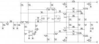
Hi-Fi Headphone Amplifier

Which is actually supplied not by the good guy who runs that excellent DIY electronic audio site.

So - i've built about 6 amps and this was my first headphone amp. First I just built the smallest power supply that fit the needs.
They list it as needing 500ma transformer 15-0-15, but I used a 300ma and just built a small simple 7815 +7915 regulator tiny thing. Then tapped into the pre-regulator for the 22+ 22- volts lines. However, since it's such a ****-weak transformer I end up with about 19v DC stable.

Its supposed to be a Class A ... which I never made yet, I made a few ClassAB and bridged sub type things LM3886 TDA2030 LM386 and so. LM386 with a push pull booster. This was my first class A as far as I understand.

Initially, because I'm lazy i was made to pay for not putting stabilizing caps on the un-regulated supply when I started testing the complete thing. So what happened was that a comedy of errors and bugs caused me to burn out one pair of BD139 BD140. When that happened the voltage really dropped as they went low resistance internally. It also burned up one driver (i was only running one side testing one channel) of my headphones.

I believe that I just had too much gain and because I didn't have caps it went into oscillation hell and killed itself. I don't have a working oscilliscope yet - i used a toy thing but that broke. So I just used my multimeter to decide I killed the power transistors.
So ... i ended up removing the arbitrary 20k resistors I put for feedback/gain on the first stage NE5532 (i didn't have NE5534 so I just used a single NE5532). So that's my first question - is a single NE5534 important - much better?

The gain on this is super important in this design from what I can tell .. so I put 2 pots so I could "adjust on test" as it said (which threw me, first time I saw that). I ended up having 0 resistance on the feedback gain (output to inverted input) so that when I replaced the power transistor push pull stage with new parts it would be more stable. I put 47uF and 100nf from the +22 to ground and the -22 to ground rather than just crossing + to -
I'm thinking maybe I should also put a bigger cap across the input between + and - unregulated input.

The opamp parts always seemed to work fine because I did, from experience, put bypass caps and resistors to their power rails. One each rail of each op amp chip. I know that you just have to do something to stabilize them or they can die quite easily (or at least NE5532 can).
Anyway - it works with all those extra caps - I did 8 caps to run the power for the 4 BD1xx transistors. I didn't put a "base resistor" for stability because it's not in the design and I didn't want to mess with the biasing. I do think that it would be better to put resistors (or even zobel) between the final output and the biasing network that feeds the base of the power transistors. I haven't tried that.

This amp is split power so it doesn't call for an output capacitor - it just goes directly out to the headphones with 10 ohm resistors to split to two outputs. I put a switch with a zobel network of just resistor cap to ground so I can turn it off/on. I did this figuring that maybe it will reduce chance of heating up the driver if something goes wrong again and it oscillates. After I damaged my headphones I tested with transformer (600/600) between headphones and amp (that I use for isolating various things from amps when testing or just generally) After that seemed like the amp was running ok it obviously sounds way better to run headphones direct from the amp ... with a signal from a phone headphone jack out ... line out through transformers it seems to make little difference. With headphones it makes an enormous difference - losing tones of power and clarity. Makes sense ... but I'm not an expert.

So - my zobel network is a bit odd - its 100 ohm 6.8nF. Not 10 ohm 100nf like most people use ... why? Well it just doesn't make a lot of sense to me that a headphone amp would need the same as 4-8 ohm speakers need.
I also read this High speed amplifiers for audio
It suggests interconnect zobel can make sense and even pushes for even lower values.
So why is that relevant - to my mind the op-amp output is part of what goes direct to the headphones. Its mixed with the power stage ... probably to supply the lowest voltage on for whatever is lost in crossover wave gap.
The biasing network makes it such that 0.7v +/- is already present at the base so you shouldn't get much to trigger the amplification of the + and - swing of AC signal - ie negligible crossover distortion but what might be present is replaced with the op-amp signal of the pre-amp or maybe its a driver. Its an active volume (bandaxall) op-amp design what has a voltage follower into a final amp supposedly giving a gain of 10. This would be why putting too much gain is a big mistake.

So my idea was that the zobel network is also dealing with the opamp driver signal and not just the output push pull stage so decided to use something oriented at reducing high frequency distortion (reactance related). I am happy for people to tell me why I'm wrong and if it makes sense or not to experiment with zobel network values.

I also saw a zobel network calculation for 68 ohm resistance + 1nf (ceramic cap) suggested. That would sort of match a 68 ohm resistor between the biasing diode and the base of the push pull amp so I think that kind of zobel network would be something that goes between the opamp driver and the input to the push pull part of the headphone amp. I think anything to reduce distortion on high frequencies is going to be a good thing. I don't know that I can perceive high frequency distortion but later if I use high impedance headphones (that I don't own now) maybe it would start to matter as the amp has to work harder.

I really just built this because sometimes music or video sources of sound from the PC are weak and I craved having an active but clean way to boost my headphone signal.

What I can say is that the bass is quite similar to the unamplified signal but it sounds more full and dynamic. What you seem to have from just the PC sound card is an adequate but hollow (compressed) reproduction but the amp seems to expand (decompress) in some cases the dynamics again. That would indicate that the compression is a function of not being strong enough to drive the headphones (even low impedence 30 to 40 ohm headphones) so it can make the tones but not reproduce the dynamic envelope of the notes as recorded. Other than this the DAC from the PC sound card is not bad sounding for an "on motherboard" one. I think DACs matter and of course I want to do a dac project can fit that with this amp. I am capable of digital electronics projects - so maybe I'll try that some day. Or I'll just buy some DAC chips and integrate them into another amp and have a USB to headphone amp thing.

So other oddities - the first gain stage if you use 0 resistance from out to inverted pin you get a hiss. When you add some resistance (and thus gain) the hiss goes away. So this is why it says "adjust on test" - you need some but not much gain before it goes out to the active volume control.

My active volume runs a bunch of tiny hookup wires to a stereo pot - so there is extra wire distance so I could run the volume to a different part of the case. If I designed another I'd put the stereo pot on the circuit board.

Audio Analogue Puccini

Hi!

Has somebody any experience with the Audio Analogue Puccini amp???

I read about a lot of good things and test and the amp is also very well documented. It has only one "problem": the bass is not enough punchy and dynamically.... (even the S.E. version)

if you're looking for a punchy and dynamically involving amplifier please DON'T buy the Puccini. But if you're looking for a sweet and smooth Music lover...look no further

Maybe we could cure this problem with some more bias🙂

Greets:

Tyimo

2.1 Boom Box Design Questions

Hi, is there any calculator to help give me a clue on a 2.1 stand up boom box style enclosure ? I have the Digital Amplifier Board 2.1 TPA3116D2 DC on its way,

the goal is to have a semi portable enclosure with maybe 2x 6.5" and 1x 10" in a stand up box about 1200mm high. that way I could use a sheet of plywood for the whole thing......Does anyone have any ideas cheers Brett

Identify this film capacitor help

Hi Folks, Just wanted to refresh the speaker crossover networks and I have two caps which I believe are film caps and one side has TI 6UFJ 100VDC but the other side has the same physical size and shape but has TI 8MFJ 100VDC. See picture I have added of the 8MFJ.

Now I can recap general circuit boards etc with electrolics etc as a hobby but I am a novice at these replacement types, is the 8MF simply 8 uf? or what do you folk recommend a good brand so I can order, the 8MFJ has me a little stumped. Thankyou

Attachments

  • 504415AA-FB27-42F9-8105-A12A9B2631AE.jpeg
    504415AA-FB27-42F9-8105-A12A9B2631AE.jpeg
    222.3 KB · Views: 125

Oak Leaf - YABI (Yet Another Blameless Design)

Oak Leaf - YABI (Yet Another Blameless Implementation)

I'm happy to pick up on my hobby/passion of tinkering with electronics projects after a gap of over 30 years.

Decided on making a Power Amplifier for home use with the following broad design considerations:

1). 150W RMS Power into 8 Ohms.
2). 4 Ohms driving capability (I believe that would be 260W into 4 Ohms).
3). THD within 0.05% at 250W RMS at 4 Ohms and 20KHz.
4). Least number of components to achieve the above.

It seemed to me that the blameless design would fit the bill. In any case, this design is one of the most detailed and documented out there. Hence went along with it.

I have tried to pick the simplest but effective design elements for each of the stages (Input / VAS / Output), to come up the the prototype that I am now posting.

I also went ahead and made the PCB layout just for the sake of completion, and also to help me learn the software that I used for the purpose.

I would love to hear what I have done right, and of course what can be improved both in terms of the schematic and the PCB layout.

Attachments

  • OakLeaf.V1.4.Schematic.JPG
    OakLeaf.V1.4.Schematic.JPG
    119.8 KB · Views: 590
  • OakLeaf.V1.4.PCB.JPG
    OakLeaf.V1.4.PCB.JPG
    190.6 KB · Views: 577

WTP ST TIP142/147 in TO-218 package

Hi All,

for a "vintage" repair job I'd like to buy 10 each of TIP142/147 in TO-218 package (pre 2000ish). Pics attached.

Dönberg is not answering concerning the package style they stock (TIP 147), and the Ebay seller in the UK I contacted concerning the TIP 142 has yet to respond to my inquiery.

Thanks,

Max

Attachments

  • TIP147.jpg
    TIP147.jpg
    6.3 KB · Views: 113
  • TIP142.jpg
    TIP142.jpg
    15.6 KB · Views: 108

Recapping Thread

I just finished a recapping project on my Meridian 557 Power Amp and was pretty surprised not to find any general purpose recapping threads when I was getting started. Yes, there are quite a few focused on specific projects but I didn't find any with general tips and ideas to help someone start and complete successful recapping projects. Does anyone else feel like this would be useful?

D

Fender Twin 1973

Hi,

Im working on a silver face twin reverb from 1973. Ive replaced the 5 larger filter capacitors, powered the amp, checked some voltages, and discharged the capacitors. After that I put the capacitor cover back on and flipped it over.

My question is about discharging capacitors from the opposite side of the chassis. The two larger capacitors I discharged at one leg of the stand-by switch. I am studying the circuit to make sure I get all the discharging spots, but would appreciate any suggestions.

Thanks

Attachments

Project V : RISCV Audio SoC

Hi all,

I have been working on a new RISCV audio processor targeting Artix FPGAs.

The RISCV core has been custom designed and extended with new custom MAC audio instructions. A new octal MAC instruction adds a 48-bit audio pipeline with 80-bit accumulators.

A register file holds 38,400 30-bit filter coefficients in 6.24 format. This register file can store for example 8 channels worth of coefficients each with 4,800 coefficients making processing filter taps on 8 channels simultaneously/ sequentially in as few cycles as possible. At 250Mhz would give a potential 2.0GMACs.

A new configurable i2s, TDM and DSD interface has been designed from the ground up. Each interface supports up to i8s or 64ch TDM. Two external master clocks are used for timing with internal dividers. Each interface can use the system clock via FPGA PLL or either of the two external clocks. There can be as many interfaces as required and FPGA I/O allows. Each audio interface has sample FIFOs that can be monitored from the drivers.

The SoC will support TinyCore Linux and Zeyphr.

Technical details to follow in November. Watch this space!

Stereo to Mono Western 111c Coils

Hello - read through every thread I could find on stereo to mono conversion, heated debate on what the right technique is and I'm certainly not broaching that topic here.

I have a couple 111C western electric repeating coils I was hoping to use for this application as they are just collecting dust otherwise. Would someone be able to assist with the wiring diagram for these? I'm fairly green when it comes to reading a schematic and building my own solution thereafter though I'm sure this isn't a massively complex task once you know where the wiring goes.

I've included the 111C diagram below for reference, really appreciate any advise you're able to give.

Thanks again!

Attachments

3e Audio TPA3255 Rev. B PFFB

I recently assembled and amp around the 3e Audio EAUMT-0260-2-B board. It sounds awesome, but the voices/higher frequencies are popping out a bit too much, probably some feedback could change this.

I was wondering if anyone had the drawings/PFFB modification instructions of the Rev. B board, since on the website of 3e Audio I can find only the instructions/manual of Rev. A

Emailed them and the answer i got was:
"the manual on our website is refer to B version.
did you check that?"


...which is not true

any clue?

Cento subwoofer CS 300 s2 ported enclosure

Hi DYIers,
I'm planning on putting a Cento 12"sub woofer and enclosure in my 2016 Mustang. I plan on using a Kicker Key 500.1 amplifier. Does anyone have experience on this driver in a ported enclosure? I have about 2 cubic ft of space I'm wanting to allocate for the enclosure. The plan is to have the speaker and port firing forward into the car.
Thanks
Max

How do you size a capacitor for a B+ node?

Hi All.

I am posting here to ask if anyone knows how to calculate what size a capacitor should be for a given B+ node.

Is there a method that can be used to figure out what value a capacitor should be to properly supply the B+ node for a power tube and the B+ node for a driver tube?

This question is not about having adequate filtering in the supply. Let's assume the supply is well filtered.

Thanks in advance for your replies!

I should add that I am mostly interested in how this applies to single ended triode amplifiers.

Foshan Blue Rocket Parts

Does anyone have any experience with parts made by Foshan Blue Rocket Electronics? They are distribution through LCSC/JLCPCB. I ordered some of their version of the 2SA1837, the 3CA1837, as well the compliment. I'll run what tests I can on them and also try swapping them into a few circuits in place of the real McCoy Toshibas, and report back. Just wondering if anyone else had come across these.

Loud without sounding loud?

Having been used to a pair of cheap 8 ohm 7.5W or 10W speakers on the desktop, I now have some second hand Mordaunt-Short MS35Ti now that I'm using on my DIY amp.


They sound different. I will need to open them up to check the capacitors.


They sound loud without really appearing loud. Not sure how to explain that, perhaps they have less distortion or something.


Is there a phenomenon for this, if so, what is it?


Anything I can do to make sure they are sounding ok?

Fix for FM syntheized tuner slightly off channel

I have a Technics ST-Z780 AM and FM stereo tuner. Probably lower end of their product line. In any event, I was getting distortion on FM stereo reception, as if the highs were getting mangled. Mono sounded fine. Noticed that the tuner appeared to be not accurately tuning in stations. Tune a station 100KHz low, and signal was weak, tune 100KHz higher and signal was significantly stronger.

...The following assumes expert knowledge of radio electronics...

Which means that the synthesized local oscillator (uses a LM7001 PLL chip, with a crystal reference oscillator) was a little off, causing the station's signal to get clipped on one side of the IF's passband (a ceramic filter). This clipping will impact the higher supersonic audio frequencies (the stereo difference information is on a supersonic suppressed subcarrier). Thus why stereo sounded distorted, but mono was fine.

attachment.php


I modified the reference crystal oscillator circuit. Used a variable capacitor trimmer (5 to 20pF) to replace a fixed 15pF cap on the osc input pin of the LM7001. This allows me to slightly change the crystal oscillator frequency, which in turn will make the PLL chip's synthesized FM front end local oscillator be more accurate (10'7MHz above the desired FM radio station' frequency) As I twiddled teh trimmer, I'd tune 100KHz above and below a station, to get a condition where the signal strength was equal. And check 200KHz high and low too, both should be equally weaker as well. And of course the station should be strongest on its frequency. You might need to tweak the FM IF receiver chip's quadature detector coil (if there is one), as the IF frequency has moved a little, should now be in the middle of the IF passband.

Attachments

  • crystalosctrim.jpg
    crystalosctrim.jpg
    8.5 KB · Views: 2,603

Sizzling/buzzing noise for a second when turning the amp on

I have a weird issue with my old Denon 970 amplifier, it makes a sizzling/buzzing sound after it's been off for a while and it has to charge the main PSU caps. After it's charged, the sizzling noise stops.


I've checked the caps around the protector circuit and the relay has had its contacts cleaned but the issue is still there.😕 It doesn't seem to come from the power switch either.

New build Tu-8340

So my system is the 8200 and the 8500, built them both no issues, awesome sound. Decided to go with the big power for the future, so I built the 8340 before it was not available. Again, what a great kit. I updated the coupling caps to Wima MKP10's. Only issue I had was a bad solder connection on a pin to OPT on one channel. Victor called me on every step of this troubleshooting and we got it done....Wow, this amp is massive, sound is incredible, thanks, to Victor and all support in Japan.....

Tannoy System 800 never sounded right

I have a pair of Tannoy System 800 monitors that I got many years ago in a closing down sale. The sound of them has always puzzled me. The specs look great on paper, but they just don't sound right. They are OK as nearfield monitors (apart from the size!) but when used in an ordinary room as hi-fi speakers they sound very dull and lacking in high end, and the midrange seems recessed and muddled too.

I'm guessing this might have something to do with dispersion. I noticed that Tannoy fitted a dome tweeter to help out the coax driver in later models. Does anyone have any thoughts on the matter?

Hello and thanks

Hello! I managed to find my way here after searching Google for a few heat problems I'm having with a Rotel amplifier. Solved all my problems, so thanks for your forum. Planning to stay for a long time

They got out of the car, walked to the house, and she opened the door. He just admired the view following her dreaming of ******* that sweet *** of hers. He wondered if she would be into anal intercourse, little did he know yet just how much she was into it. They stepped through, and she closed and locked the door behind them. While she was facing the door and locking it, Mike stepped up behind her and grabbed her tits, and started kissing her neck. She moaned in pleasure and reached down behind her *** to grab the **** in his pants. He was much harder now, so she let him grind that **** into her *** right at the door. live cam sex

He pulled her top off standing there at the door, and took her sexy black bra off too. Her perky tits were free, and he had one in each hand squeezing and pinching her nipples. She loved the way he was taking control and ravaging her in her own place. Becky turned around and kissed him some more, till he went down to kiss her nipples. He kissed and sucked as she leaned back against the door to be open for him. web cam girls

Breaking the kiss, she grabbed his hand, and lead him to the bedroom. “Get your clothes off Mike,” she ordered, and he was peeling them off leaving a trail to the bedroom. She backed him up to the bed. His shirt was off, his pants were undone and around his knees. She pushed him back on the bed, took off his shoes, pulled his pants off and then took his boxers off. There he was naked on her bed. nude cam girls
Projects by fanatics, for fanatics
Get answers and advice for everyone wanting to learn the art of audio.
Join the Community
507,743
Members
7,886,335
Messages

Filter

Forum Statistics

Threads
406,147
Messages
7,886,335
Members
507,743
Latest member
Fitodiod