Oh no, another Zintolo's thread about that ####### Baby Huey?
Yes. This time with building notes.
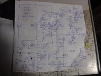
As some of you probably know, before assembling the pcbs I decided to study the project and I got bored alot of you with silly questions and pedantic arguments. I'm sorry for that, but I'm glad it helped me understanding (partially, as I'm sure I'm still missing alot) the circuit and the design process that lead there.
Everything started from Yves Monmagnon "Dissident Audio" ECL86 amp:
Push Pull ECL86/6GW8
Then it has been further developed by Ian "Gingertube" by substituing the ECL86s with a 12ax7 and two EL84 (that are equivalent to the ECL86 indeed).
Then UL has been integrated (instead of the original and preferred by Ivesm pure pentode) to reduce the THD of the EL84s, but with Hammond trafos with 43% UL taps, the ratio is not the right one (see here:
http://www.oestex.com/tubes/Rudolf Moers - Appendices.pdf and here:
UL for EL84. 22-24% is better than the dogma....40% is lowest distortion.... ).
Then it has been modified the CCS on the tail of the PI to increase the AC impedance and so improve the balance of the phase inverter. Total current of the CCS passed from original Yvesm value of 1 mA to 1,2 mA and no more than 1,4 mA (700 uA per side).
Then it has been applied the trick to reduce 3rd harmonic content:
EL84 Amp - Baby Huey
Then the output tubes have been switched from cathode bias to fixed bias to improve the recovery when overloaded.
Then powerdrive has been applied, with a simple resistor on the mosfet.
Final developement has been to increase the driving capability of the powerdrive by applying a CCS instead of the simple resistor to load the mosfet of the Powerdrive.
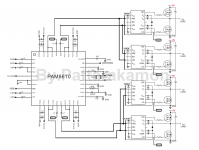
About R33 and R38:
to fully drive the EL84 I need around 25 Vpp (a bit more if I want to reach AB2) up to ten times (to be conservative) the bandwidth, so 200 kHz, so slewrate will be:
2 x pi x f x V = 2 x 3,14 x 200 kHz x 25 = 31,4 V/us
One EL84 has an input capacitance of 11 pF (let's say 15 considering wiring?).
C = i x dt / V
dV/dt = 31,4 V/us
then
15 pF = i / slewrate
so
i = 15 pF x 31,4 V/us = 470 uA
The current of the CCS is 0,7 / R33 (or R38), so we'll need that resistor to be less than 1.5 kOhm. I will keep the original 390 Ohm.
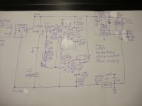
Powerdrive AC voltage supply
Being the negative side of the PI's CCS connected with the negative rail of the Powerdrive circuit, the voltage is set by this one at 3 times the bias voltage (
EL34 Baby Huey Amplifier ).
So for a EL84 amp with approximately -12 Vdc it will be around -35 so, multiplying by squared root of 2, a 50 Vac winding is needed to supply it (it's called BIAS on the pcb).
About R16 and R17:
On the BOM and the PCB they are shown as 1.6 kOhm and 1 kOhm respectively, but this is due to a very early version of the Baby Huey, not the current one.
The guideline is to keep the current of the led of the PI's CCS between 2 and 5 mA, preferibly towards the lower value. In both versions, EL84 and derived EL34, R16 is around 1.5 times R17. I still don't know why, but I'll keep this proportion.
So considering the small losses in D5&R28 plus the drop due to the led, we have around -33 Vdc to be dropped by R16 and R17 with around 2 mA.
Then R16 + R17 becomes 33 Vdc / 2 mA = 16.5 kOhm. Then I decided to have R16 = 10 kOhm and R17 = 5.6 kOhm. This leads to around 2.1 mA.
About R3 and R4:
On the BOM and the PCB they are shown as 1 kOhm, but this is quite low as a value.
The old guidelines for triodes were to use 8/gm to set the grid stopper value, so with a 12AX7 which gm is 1.6 mA/V the value would be around 5 kOhm. In my guitar amps I always use at least 10 kOhm because gm of the tubes goes down with age, and I want to be sure there are no issues even when tubes are almost gone.
With an avarage value of 12AX7's input capacitance (Miller included) in the order of 150 pF, 10 kOhm gives a low pass filter with -3db point at 106.1 kHz. I would say it's plenty acceptable.
IMPORTANT NOTE: carbon comp here is the best choice, because they are the resistors with lowest capacitance and inductance, and that is what is needed in this position. I used carbon film, the second place in the choice.
About R7 and R8:
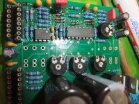
In the BOM they are 600 mW resistors, but they need to be 1 or 2 Watts, because of the voltage they see across them (remember that they are connected to the shunt feedback system that is directly connected to the primary of the output transformer.
Of course I noticed it only after I soldered all resistors, so by now I decided to install 2W metal oxide resistors on a pair of pcbs and keep the BOM ones on the other two pairs, in order to be able to check the differences.
On my experience with guitar amps, higher wattage on plates of preamps gives more dynamics and more definition to the sound (over there there's need to get higher THDs with specific harmonics), I'm curious to see if it applies to this scenario too.
About R14 and R15:
On the pcb they are shown as 270 Ohm, on the forum someone suggested to raise that value to 1 kOhm to be on the safe side. I'll start with 270 Ohm (originally gingertube used 33 Ohm) and I'll see how it will react. I would say that this value depends also on the working conditions of the tubes: with pentodes they must be higher (because screens have higher potential than anodes, so secondary emission is higher), then optimal 23% UL is in between, and 43% distributed load will need them lower. I'll use 23% UL connections and 270 Ohm by now.
About R20 and R21:
They are shown as 470 kOhm on the pcb, but I used 1 MOhm instead.
The reason is these resistors are part of the load seen by the PI (detailed description here:
EL84 Amp - Baby Huey even if it refers to the old schematic without powerdrive), and even if the difference between 470 kOhm and 1 MOhm when in parallel with 64 kOhm is small, why make it worst?
I think the 470 kOhm value comes from the pre-Powerdrive indications, because that was the grid-leak maximum allowed resistor for EL84. Now it is no more, so 1 MOhm is better.
About C1 C2 and C5:
Here the value shown on the pcb is 220 nF. For C5 I remember it's the 1/100 rule based on the main power supply cap, so C6 in this case.
As for C1 and C2, this value is very high. I used 100 nF for all three because the coupling caps with 1 MOhm load will have an high pass filter with -3dB point at 1.6 Hz, so one order of magnitude lower than what can be heard.
I used the suggested Vishay Ero 1813 because I already used them for my guitar amps and I liked them, then I've seen some suggesting them for Hi-Fi as well, so before investing 10 € for a cap, I give them a try.
Suggestion on it?
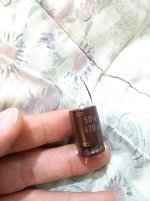
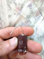
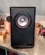
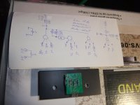
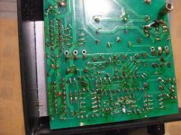
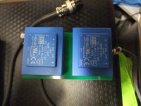
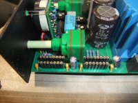
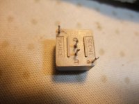
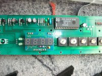
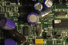
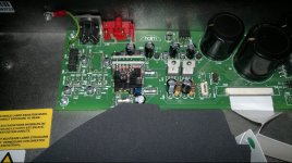
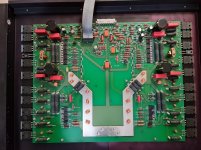
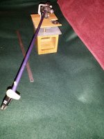
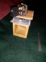
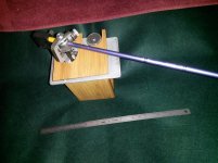
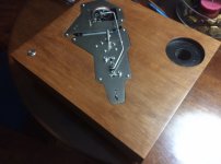
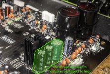
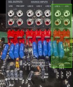
In attachment you can see the boards with the standard R7 and R8 resistors, and with the 2W metal oxide ones.


![IMG_2978[1].jpg](/community/data/attachments/789/789757-250911103b31d2dce8f7d2c9ded67840.jpg?hash=JQkREDsx0t)