This a guide on how to attach your heatsinks to achieve 10-20% more efficiency without changing the design.
Is this necessary? In most cases, probably not. However keeping your amp cool is always a good thing and ultimately translates into better reliability.
One thing you should be aware of is that this process will make it hard to pull everything apart again. There is no thermal epoxy involved, but the "suction" effect is so strong that I've ripped chips from their sockets trying to get them apart. If you do have to remove them, remember to use a slow lateral motion before you pull on them.
Wet Sanding
On both the heatsink and the transistor there are imperfections as well as oxidation that impede thermal transfer. This is especially true with older transistors.
(large)
Attach some NEW 800-grit wet/dry sandpaper to a sanding block. If you don't have a block then white-glue the sandpaper to some masonite. It works as well, if not better than a block.
For the heatsink, use copious amounts of water and gently sand back and forth with the metal grains. The mill marks will be inline with the metal grains. Deviating from this method will cause score lines the metal that will take twice as much work to sand out.
Sand with 800-grit until the surface "breaks". You'll feel the surface break when the block no longer sticks to the surface when you stop, but instead glides back and forth easily. Repeat the process for 2000-grit. The surface will break just like the 800-grit. Clean the surface with rubbing alcohol. Note that you'll never get a mirror finish with milled aluminum.
For the transistors, flip the sanding block upside down and add a very small amount of water. It's better to keep adding a few drops of water rather than submerging the transistor. The water shouldn't harm it in either case as long as you clean it with rubbing alcohol afterward. Move the transistor in a circular motion over the block with your fingertips. If you're OCD then use a figure-eight motion. Don't go overboard here. There will be a natural dip in the metal surface that can't be completely removed without potentially damaging the component. 50% flat is still 50% flatter than it was before.
Don't worry about removing the nickel plating. The surface will be sealed.
(large)
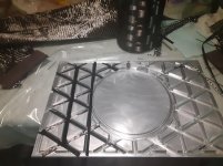
You should now have perfectly flat surfaces
(large)
Thermal grease/paste
Next, add a 3mm dab of thermal paste to the transistor. Less is more because we want the thinnest layer possible to cover the whole surface. I mean like microns thick! You can add more if it doesn't fully cover the surface. If there is one area that just won't cover then the surface is not flat enough and you may choose to go back and do more sanding.
As for brand, I have arctic silver but it really doesn't matter that much. The only thing I would say is that mil spec is more durable but also too thick to get a precision thermal layer.
(large)
Now, I use a razor blade between my thumb and middle-finger, using my index finger for stability and to prevent the blade from flexing. I generally hold the transistor in my left hand but I had to put it down to take the picture.
(large)
Important: Once you've spread the paste in every direction, then you must go over the entire surface in the
same direction for 5-10 swipes. This is akin to cracking clay, in that you're aligning the paste particles so they fit together perfectly.
(large)
Next, clean the mica sheet with alcohol and place it on the paste. Turn it over and press it on a surface. You can use your fingers but remember to clean the top of the mica with alcohol again.
For the second layer of paste, it's much easier to apply it to the heatsink but you waste more thermal paste. Adding it to the mica can be tricky because the layers like to slide around and you have to repeat the "cracking" process which pushes the mica in one direction.
(large)
Finally, carefully lay the transistor down on the heatsink, imagining where the holes should line up. I can usually finesse all the layers into alignment with the screw. Rather than cranking the screw down and risking cracking the die, just snug the screw down while holding everything in alignment. Wait awhile for the layers to compress and then snug it down again.
If you care what it looks like, then clean then excess paste away with rubbing alcohol.
(large)
Part 2 (passive convection) to be continued...