Hello!
I recently inherited a bunch of stuff from a fellow DIYer, and one of the things was a nice chassis suitable for a preamp or perhaps Chipamp with an outboard PSU. Discussions with other members, as well as a healthy dose of curiosity led me to choose the B1. It went together very easily and quickly. Here is the log of that build.
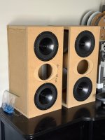
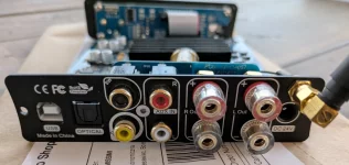
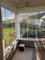
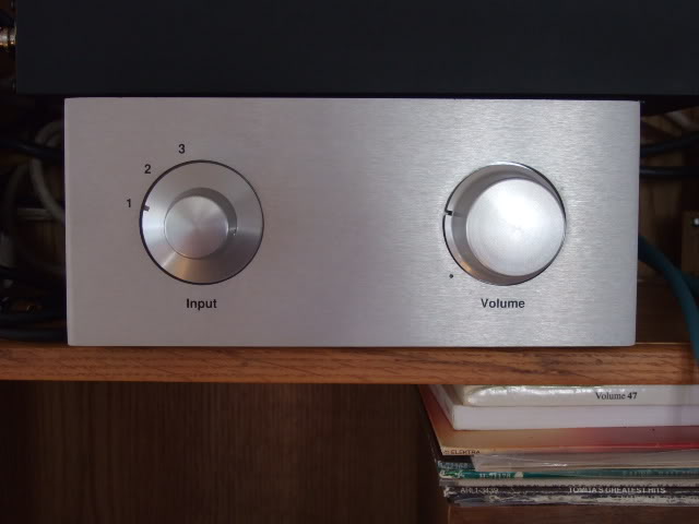
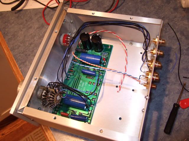
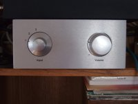
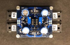
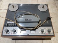
The finished product. It sounds fantastic!
But how did I get there? well...
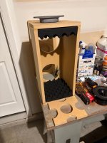
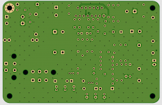
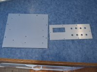
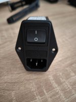
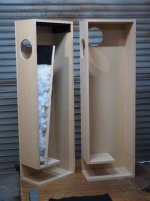
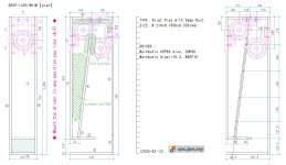
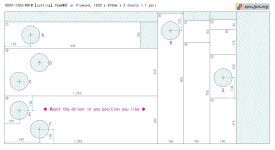
When doing a project like this, the easiest place to begin (for me, anyway...) is the mechanical. Drilling, hardware, things that touch the chassis. Not a lot of drilling was involved, the power inlet module was pre-cut, so I added the holes for the RCA jacks and the screws for the circuit boards and transformer.
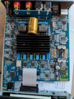
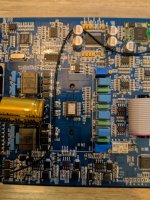
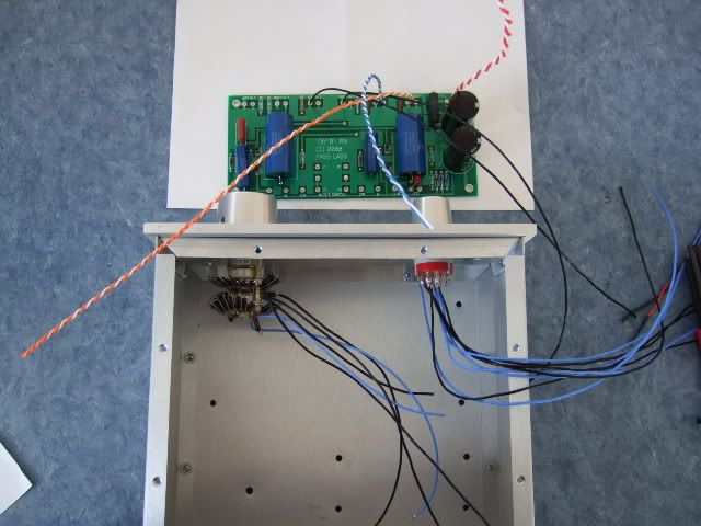
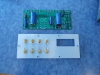
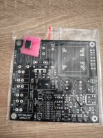
This is just placing the various boards and transformer in place to see how things will fit. The blue board shown in this photo is actually a dual-rail PSU PSB from Peter Daniel, the single rail is exactly half of it.
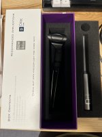
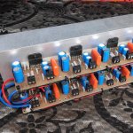
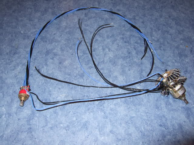
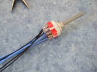
This is a really nice Goldpoint switch and series stepped attenuator made from a Elna 24 pole switch and a bunch of Holco resistors. It's all wired up because it was salvaged from a different project.
You will notice in this photo that the grounds of the inputs are wired together. This is for two reasons... firstly, the RCA jacks all float on the chassis - the shoulder washers isolate the jack from the chassis. Also, the PassDIY circuit board has a pad for ground on both left and right... so there will be wire connected to one of these negative tabs to the PCB pad.
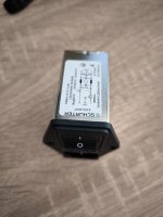
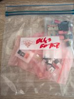
A well-stocked junk box to the rescue!! This switch is the one I had to use in the end... the Goldpoint that was on the harness with the attenuator had a shaft that was just too short to use with the knobs on the chassis. This switch was bought only a few weeks ago as I was perusing through the local surplus store and saw this switch perfect for a preamp. Luck favors the prepared!
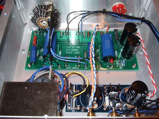
So here are the selector and the attenuator mounted, and the PCB with some of the wires soldered in place. In order to keep the wires as short as comfortable, it is prudent to solder all of one edge in place, and then you only have to do the other edge in place. if you do this, make sure that your wires are at least a couple of inches longer than you know you will need. Too long you can trim, but too short is a pain in the backside!
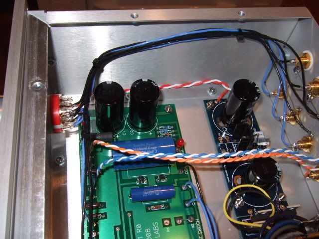
The wiring continues.
I originally envisioned the preamp board turned the other way, to keep the leads from the RCA jacks shorter. The size of the attenuator happened to get in the way of the black electrolytic caps, so it got turned 180deg.
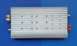
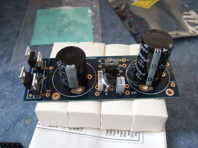
Here is the single-rail universal power supply PCB from Peter Daniel. It's a very nice board, with the ability to choose 2- or 3- pin diodes (or none at all), many different lead spacings on the filter capacitors, and either a LT1085 or LM317 regulator. Shown here are MUR860 diodes and a LM317 regulator.
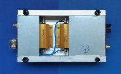
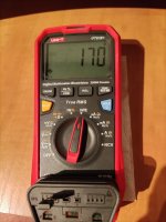
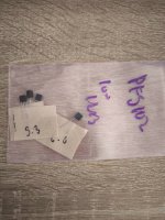
When I first fired this up I couldn't adjust it to get more than about 7.5-8 volts on the outputs... I was slightly confused, and knowing that just thinking about it wouldn't fix anything, decided to measure the components... It turned out that I grabbed a 240K ohm resistor when I need a 240R...
😀 Anyway, I didn't have anything close to 240, but I happened to have two 150R that are now placed in series in that position, and it works very well now! The range of adjustment is about 17-25 volts, and have it set at 19.5v
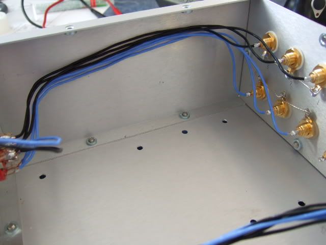
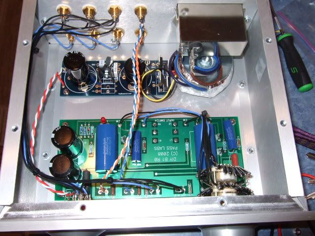
This is the last check of the wiring to see where the power supply wires will place.
Just to recap, the black and blue are signal input, switching and attenuation, the red/white is from psu board to preamp board, and the blue/blue-white, orange/orange-white is the output.
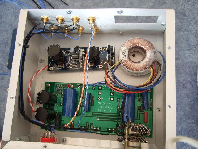
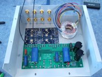
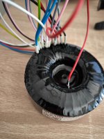
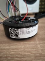
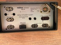
And here it is complete - the power inlet module is installed and above the transformer, the yellow/black leads are the secondary of the transformer.
This was a very easy and rewarding project. I cannot express enough gratitude to both Nelson Pass (you rock!) and Peter Daniels (you also rock!) for making the circuit and and the PSU board. Although something like this could be very easily made on perfboard (and I thought quite seriously about it) any project is greatly simplified by good circuit boards!


![PXL_20250325_202858459.RAW-01.MP.COVER[1].jpg](/community/data/attachments/1348/1348055-09583308872285fe6518e5759550b66f.jpg?hash=dWEA0eTIVL)