Help with a bookshelf build please...

I'm looking for some help-insight on a bookshelf build... one of these two:

Falcon with FF105wk
Storm Shadow with Pluvia 7 PHD

I've had the FF85wk and really enjoyed them... I like how more front stage the presentation is and how they performed at low volumes... is the 105 similar with better bass??

And I have no idea how the 7PHD is as the only Mark Audio driver I had was the EL70. While it was a little further back in the staging and had way better bass... it was not as good a low volumes so comments would be appreciated!!

I'm not concerned about top end as I don't hear past 10k anymore. I'm more concerned with proper tone and easier listening... nothing hard or brass or sibilant.

I'm guessing the bass output of the MA with be greater?? Better midbass??

What's the 7PHD like in the midrange?? As natural as the Fostex??

Any help would be appreciated... thanks!!

Grundig T5000 Tuner won't hold the time when switched off

Hi,

I have a lovely Grundig T5000 tuner which seems to work lovely, apart from retaining the time when it's switched off.

I don't have the User Manual, but I can put the correct time in using the buttons on the front, but when it's switched off it doesn't retain the time.

I think the time is battery backed on a MCM5101P-65 chip, so am wondering if this could be the issue, and if I can get a replacement (can't see any on Ebay), or an alternative?

I get approx 3.6volts on pin 22 when there's no power to the unit, just the batteries. Which seems about right.

Please see the attached pictures or further information.

Thanks, Rob

Attachments

  • IMG_20210625_155108.jpg
    IMG_20210625_155108.jpg
    524.9 KB · Views: 293

Cambridge Audio 340A - intermittent right channel

Hello people of DIYAudio!

I thought I'd join the forum as I found a few posts about this amp so I thought I'd see if anyone that knows anything about these amps is still around and could perhaps give me some pointers.

I have been experiencing an intermittent problem with my 340A whereby only when outputting to loudspeakers (all fine through headphones), the right channel will go quiet and weak, distort or cut out all together. Clear audio will usually come back if I turn up the volume to about half way, kind of like revving an old car when it's about to die, then the audio will kick back in, I'll turn the volume back down to listening level and the audio will play nice and clear thereafter - if I adjust the volume and/or balance knobs the audio will remain clear.

I have tried 'working' the volume and balance knobs in case of dirty pots but seems to make no difference, other than when I mess with the volume knob to get clear sound back when it's playing up. I'm unsure if this would be the cause of the problem anyway since the distortion etc. happens to my R channel and the L is always loud and clear. Sometimes even this method won't work and I have to power cycle the amp a few times to get audio back through the right channel. Sometimes the fault will also happen randomly when the amp has been working fine for a few hours.

I've tried using different input sources through different input selectors, swapped the speaker leads and RCA input cables but this makes no difference.

I've had the amp out of its chassis and had a look at the components - nothing appears to have burnt out and I couldn't see any dry joints. Would it be out of the question to suspect the chip has blown on this channel?

Just for information, the amp was bought used and had been used pretty much daily for around two years now before the fault arose, powering a pair of 4ohm 'studio monitors'. I'd done a little digging on this amp looking for a fix and have seen posts suggesting against 4ohm loads for these amps so maybe that's what's caused my problem!


Anyway thanks for reading. I welcome any suggestions, I'd love to get this amp going again!

Cheers

Accoustic assault

Not sure where to post this. Does anyone have any ideas on how to design a setup capable of delivering a SPL of 130db at about 10m using a class d amp. I have some neighbours who are using music as intentional harassment towards our house. This is because i asked them to turn the music down late one night. They randomly point speakers towards my house and play very loud music for relatively short periods of time at night when they are having parties and think it is very funny. They know that it will take the police an hour or two to arrive and turn it off before they are likely to arrive.

I have read a bit about the use of high volume high frequency accoustics as a deterent. I have seen various devices for sale online but they mostly seem like scams. I am wondering if it is possible to make a powerful device to deliver a 20-25khz signal at 130db or more at about 10m in a very directional way. The idea is to create discomfort.

My immediate thought was some kind of class d amp with a digital single frequency tone and appropriate speaker capable of handling power and frequency. Anyone have any experience in this or have any theoretical suggestions for a suitable amp or speaker deaign?

boyuu A9 simple newbie questions..

Hello all, I have a few questions if I may. I apologize, I was only able to figure out how to insert a photo of the Boyuu A9's schematic.

(1) Are the 0.22uf "C102" the coupling caps?

(2) I know this may not be an easy question, but is there any info on the web
someone could recommend to convert this particular amp to allow for
6L6's?

(3) Is it safe to assume I can use 6CA7's as is?

I purchased this amp factory build on Amazon. What a nice little amp! It runs
my Klipsch speakers very nicely.

Attachments

  • boyuu a9.jpg
    boyuu a9.jpg
    50.5 KB · Views: 246

Amp for off grid system

Hello, I have build an off the grid system, based of 36v batteries, with 1000wh capacity. Everything is carried in a bicycle trailer and play music outdoor to 50 100 people
It has a 12" JBL subwoofer 50l box 4ohms ( rate at 200rms) and a 12" full range fane sovereign ( rate at 250 RMS) 52 liter enclouser 8ohms
Currently I am using an aiyima 2.1 tpa3255 amplifier. But I want more power.
https://m.es.aliexpress.com/item/40...&spm=a219c.12010612.8148356.10.3cf47340bNi80O

Currently based on battery consumption it runs at 30w or 40w at max volumen. I could run it 48h non stop!. but I will want to run it with more power, something close to the the RMS power of the speakers.
I have a preamp to step up the input voltage of the music.
The current amp 2.1 is BTL for the subwoofer and se for each channel , and only using one channel for the fane and subwoofer . Not ideal.
I don't know if I could take more power from the actual amplifier , or I need to switch. The specifications advertised are wrong, but I realized that too late.
My idea is to change to two mono amp which are pbtl, to get the max power possible from the 36v battery.
Either a tpa3255 from 3e or a wondom
WONDOM AA-AB3124?
I will need to split frequencies somehow , probably a DSP because I want the system to be efficent.
What amp do you recommend? Is there a better combination of amps or other way run the system .

Tda2030 2.1 amp noise problem

Dear all please suggest what can i do... Basically its a tda2030 based 2.1 circuit for some reason the satellite speakers makes a humming noise. It goes away as soon as i touch the heatsink with hand. So i thought it might be grounding issue as the heatsink was negative thus made a hole in the heatsink and took a wire and connected it to ground (used isolator to separate ic from heatsink) but now the noise is same as before and cant touch the heatsink as it shows high voltage that is dangerous to touch with bare hand. Please help 🙏

Cronus > S/PDIF Transceiver problem

Hi, Can anyone help please I need to convert to SPDIF so I can insert a MiniDSP before my DAC

Old working setup:-

BBB Hermes Cronus i2s > Teleporter .......I2s.....Teleporter > Buffalo-IIIsePro28 (other S/PDIF sources working fine)

New Setup:-

BBB Hermes Cronus i2s > S/PDIF Transceiver......S/PDIF........ Buffalo-IIIsePro28 (no lock)

Cronus > Transceiver connections
DCL > BCL
D1 > LRCL
D2 > DIN
GND > GND (via p/s)

Switch settings see photo

20210627_164528.jpg

20210627_163130.jpg

The LED's on in the photo are the same with or without clock and data lines connected.

Can anyone confirm the connections and settings are correct please.

Cheers, Steve

Soft X-rays / EUV inside the envelope? Q for physicists

It's well known that if you've got tubes running in the 10's of kV range then X-Rays become a concern. Obviously this is of no concern or worry whatsoever for every day audio and radio tube voltages.

But here's what I was wondering: Since visible light is only around 2-3eV and tubes run in the 100's of volts range, are there technically high energy photons as a result of this? Obviously they aren't getting through the glass but technically, do you get super short wavelength photons from the typical acceleration in say an output valve? Obviously not typical x-ray wavelengths but somewhere at the end of the UV spectrum. I simply don't know the physics around this and whether or not this happens proportionally or you have to get over some threshold for things to get interesting!

Beginner question, different power/ground names? Definitions?

What are some of the common power/signal short forms on amplifier circuit boards?

A general Google search comes up with the electrical definition, but not necessarily how they are used on an amp board.

These are the easy ones,

SGND = Signal Ground

In = Signal In

Out = Speaker Out

Now how about,

PGND = Power ground, I take it this is "0" from a +0- unregulated power supply, but not chassis ground?

When there is no "Speaker -", where do you connect it? (I see this on many Apex amps)

What other common short forms/labels are not necessarily straightforward for the beginner?

Thank you for your patience,

David.

time alignment & phase plugs

I was recently playing with an active 2-way and the woofer had a phase plug. In order to get a reasonable null in the frequency response at the crossover point with a symmetrical crossover and with the phase reversed on one driver, I needed to add delay to the woofer which I would think suggests that the acoustical center of the woofer was out in front of the tweeter.

The design used a flat baffle. My measurements were taken at 1m, and nearly at tweeter height (The height I used is what lined up with my ears at listening distance - if that explanation makes sense. So that I would be time aligning the drivers as closely as possible for my listening position. )

Is this a reasonable and simple way for me to get a decent time alignment? Is it the phase plug that caused me to get a different than expected result? Or is this just the differences in relative phase of both drivers at the crossover point and something that can happen quite often? Am I missing something about time alignment here?

Xtant 1001d

Does anybody know the value of R172 on this amplifier? I can tell it’s part of the pwm circuit for the gate drive. I think it’s a 10 ohm resistor but when I replace it I get the powersupply to operate and rail to rail oscillation on outputs then the resistor instantly starts smoking and separates. I pulled the buffer transistors and irf44’s to confirm they are not shorted and even replaced the 9942 out of a working amp to confirm they aren’t bad. A schematic would be better but I know there probably isn’t one. I took out the rectifiers also to separate the powersupply from output section and R172 still smokes.

Aikido headphone output transformer advice needed

I could use some help selecting the superior transformer for an Aikido PP headphone amplifier. I have several 8FQ7, 8GU7, 6n1p, and 6n6p tubes.

Headphones are the Sennheiser HD 6XX (HD650, 300ohm) and possibly a 32 ohm HiFiMan Sundara in the future.

The two output transformers that I am considering are:

VDV-600-32-HPH http://www.trafco.rs/download/VDV-600-32-HPH ENG.pdf
Primary Impedance : Raa 0.6 = [kΩ]
Secondary Impedance : Rls 32 = [Ω]
Turns Ratio Np/Ns : Ratio 4.332 = [ ]
Nominal Power : Pn 3 = [W]
Total Primary DC Resistance : Rip 40 = [Ω]
Total Secondary DC Resistance : Ris 4.3 = [Ω]
Total primary Inductance : Lp 175 = [H]
Primary Leakage Inductance : lsp 0.7 = [mH]

VDV-800-V-HPH https://mennovanderveen.nl/cms/imag...H/2018-10-30_VDV-800-V-HPH_specifications.pdf
Primary Impedance : Raa 0.8 = [kΩ]
Secondary Impedance : Rls 16, 32, 64, 125, 300, 600 Ω = [Ω]
Nominal Power : Pn 1 = [W]
Total Primary DC Resistance : Rip 18 = [Ω]
Total Secondary DC Resistance : Ris 19, 9.5, 7, 5, 4, 3 = [Ω]
Total primary Inductance : Lp 40 = [H]
Primary Leakage Inductance : lsp .04, .08, .2, .7, 1.2, 1.5= [mH]

Which one of these two would be the superior option here? The VDV-800 is flexible but I do not know how much inductance is required or how much Leakage inductance & Ris should be tolerated.

On the other hand the VDV-600-32 has only one tap and presents a 600 impedance for low impedance and a 5600K impedance for 300 ohm headphones. Would this give the Sennheiser even lower distortion or would I run out of milli-watts or require new biasing different than what's in the Aikido manual?

Simple amplifier with ICEPower 125ASX2

Hi, reading the forum, I recently finished an amplifier with ICEPower 125ASX2 module, which is giving me great satisfaction.
As a simple self-builder, without technical training, I share this project with you, hoping it will be useful to someone novice but who wants a complete and well-sounding amplifier. Everyone can improve it.
I don't speak English well, so I apologize for my language. I'll ask my friend Google Translate for help.
Have a nice Sunday.

Attachments

  • IMG_5852.jpg
    IMG_5852.jpg
    847.2 KB · Views: 473
  • IMG_5875.jpg
    IMG_5875.jpg
    558.9 KB · Views: 432
  • IMG_5876.jpg
    IMG_5876.jpg
    740.5 KB · Views: 470
  • IMG_5890.jpg
    IMG_5890.jpg
    502.6 KB · Views: 672
  • IMG_5879.jpg
    IMG_5879.jpg
    792.8 KB · Views: 493
  • IMG_5880.jpg
    IMG_5880.jpg
    578.3 KB · Views: 420
  • IMG_5883.jpg
    IMG_5883.jpg
    806.1 KB · Views: 365
  • IMG_5887.jpg
    IMG_5887.jpg
    1,003.1 KB · Views: 362

The doomsday amp

There's a bit of consternation about the future of Class AB amplifiers because the transistors may get scarce, especially with the move to SMT and the ongoing semiconductor shortage.


https://www.diyaudio.com/forums/parts/373697-class-ab-endangered-8.html


I decided to take a shot at seeing how good of a power amplifier can be made using just two sets of transistor parts: 2N5551/2N5401 and TIP41C/TIP42C. In particular, 2N5551/2N5401 and TIP41C/TIP42C both have generic versions from Chinese manufacturers that seem to work pretty well, for example:


ST(Semtech)|ST(Semtech) 2N5551|Bipolar Transistors - BJT|LCSC
ST(Semtech)|ST(Semtech) 2N5401|Bipolar Transistors - BJT|LCSC
SPTECH|SPTECH TIP41C|Bipolar Transistors - BJT|LCSC
Changjiang Electronics Tech (CJ)|Changjiang Electronics Tech (CJ) TIP42C|Bipolar Transistors - BJT|LCSC


Because of the large number of versions, it seems these parts are good candidates to not be discontinued in the near future.


The result is: pretty good. The simulations seem to indicate that 180 W can be delivered to a 4 ohm load with THD 0.01% to 0.02% at 20 kHz. The design uses an output triple darlington, single ended VAS and cascode input, and is protected against overvoltage input and has a V-I limiter that cuts current when the load resistance is below 2 ohms. The power rails are up to 45 V. There is 108 dB of open loop gain with a gain margin of 15 dB and a phase margin of over 90 degrees.


https://github.com/profdc9/PowerAmpAudio/tree/master/PowerampSimpleParts


The current design uses conventional Miller compensation but there are inclusions on the board for TPC and OITPC compensation components.


I laid out a PCB for it and it seems to be reasonably compact. There are four TIP41C/TIP42C on each rail.


This could be a pretty good budget amp I think.

Attachments

  • Poweramp-Schematic.pdf
    Poweramp-Schematic.pdf
    134.5 KB · Views: 215
  • PowerampC300.png
    PowerampC300.png
    79.2 KB · Views: 755
  • TIP4142-triple.png
    TIP4142-triple.png
    92.5 KB · Views: 755
  • TIP4142-triple-results-distortion.png
    TIP4142-triple-results-distortion.png
    15.2 KB · Views: 703
  • TIP4142-triple-results-stability.png
    TIP4142-triple-results-stability.png
    66.8 KB · Views: 641

low cost high sensitivity sealed 2 way drivers (94dB+)?

Hi

A budget, high sensitivity sealed 2 way build (94dB or more @ 2.8V) is something I would like to do at some point but I'm curious to find out how realistic it is.

It is voltage sensitivity that I care most about rather than power sensitivity.
4 ohm drivers would be probably be the better choice here.

High SPL capability and well extended bass are not important,
in fact overly extended bass is undesirable, an F3 around 60-80Hz is preferable.

Having already done some research there doesn't seem to be much shortage of low cost, high sensitivity tweeters.
Monacor DT-300 was one nice example, something similar in a 4 ohm version would do the job nicely.

Finding a high sensitivity woofer that is likely to play cleanly up over it's entire range is not as easy.
I love the tight and clean bass from alpair 11MS, so I figure looking for a woofer with similar qualities (low Le, low Mms and relatively high BL to Mms ratio) would be the best bet.

The Eminence Alpha 6C looked pretty much ideal along with the price but to my disappointment it wont extend enough to be suitable as a woofer in sealed enclosure.
Surprising is that the 8'' versions are barely any better.

I have not looked at larger one because I dont think they will have enough finesse up near XO point and the price only goes up.

Are large multi cone woofers (Eminence 12LTA, Fane 12TC250 etc.) the closest thing to what I want?

As an alternative, what about a wideband tweeter that could cross somewhat lower to a larger sized woofer, sacrificing treble quality and/or a bit of treble extension?

Full rangers will trade sensitivity to get more bass extension... seems reasonable to assume you could have a wide band tweeter with high sensitivity that is good down to 500Hz or so.

B&W DM 602 crossover

Good morning everyone. I have some B&W DM602 (S1) boxes, and I have been reviewing their crossover.
I see that it is very simple, with first order for woofer and third order for tweeter.
While I like its sound, I find the treble region a bit tiring.
I have seen a modification for the B&W DM 601 that attempts to correct that problem.
It consists of modification of the capacitor in the high pass, inversion of the polarity of the tweeter and the addition of a resistor and capacitor for second order in low pass.
I show the diagram of DM601. The difference with the DM602 is that this ultimp the high pass filter has no resistors
I don't have measuring instruments, so I ask if it would be beneficial to do the same on the B&W DM602 version 1.
In this configuration, where the high pass is third order and the low pass is first order, how is the positive of the tweeter connected?
Thanks.

Attachments

  • original bw.png
    original bw.png
    7.7 KB · Views: 2,506
  • bw mod.png
    bw mod.png
    7.9 KB · Views: 1,667

Anode / grid choke good idea?

Hi all, slowly I am gathering parts for a new project to create a Headphone amplifier for my Beyerdynamic DT-770 250 ohms which has been lying around for years.

Since I like the simplicity of this design this is what I intend to build:
6AS7 Headphone Amplifier
A Single-Ended OTL Amplifier for Dynamic Headphones. – HeadWize Memorial

Now I have 2 grid chokes (Valab GC640-5 filter choke) and 2 anode chokes (Valab AP200-35 Anode) which also gather dust.

My question is if I can just replace R2 and R5 with chokes? I think in theory I could but anything I need to be aware of in this context?

Attachments

  • 6as7 headphone.jpg
    6as7 headphone.jpg
    148.5 KB · Views: 577

SMT212 using 15" drivers

As I am sometimes just wandering about some speaker designs, something came to my mind.

A little bit before the covid pandemic started I made a top speaker for a friend.
Based on the SMT212 but using only 1 12" driver.

As Always it was a compromise and i didn't used the most expensive drivers.
I used the PA310 for the 12" driver and a PRV compression driver.

I was amazed about how good this simple design can perform.
As I see it the mid section has a horn/waveguide that boosts the higher mid frequenties till around 200-300Hz.
Then it is also vented but tuned relatively high giving extention to around 100Hz with a sensitivity more then 100db/w/m.
(I measured around 102db)
If you would tune a normal front loaded reflex speaker this high it would have a bump. But the combination with the horn (or more like a waveguide?) makes for a flat response.
This is the way this cab works I think?

Having a sensitivity of around 102db makes it loud with a lot of dynamic. A really good sounding PA/Party speaker.

When I was thinking for a nice 3way top it got me thinking again about this cab.
I have made Some Xtro's years ago. They where not a perfect build but didn't sound to bad.
The 8PE21 is a good mid driver but has a difficult time in the Xtro I think.
I used the beyma 15p80Fe for the low mid. Incredible slam and punch but would be nice if it could go a little bit lower.
They where also HEAVY to say the least.


So back to the SMT212.
What if this principle was used with some good 15" drivers.
The 15P80Nd is the Nd version with a lot less weight.
I tried a quick simulation in Hornresp with 2 of these.
I got around 106db/w/m (2Pi, I find it hard to believe....)
-3db around 80Hz and -10db around 65Hz
The high response goes to around 200-300Hz but with this priciple I have noticed it will go higher as simulated. (the 12" I used had a response till around 2kHz, I did cross at around 1k5 or something)
I wanted a 3way so was thinking to put a mid driver with horn above these 2 15" drivers and make them the same length (if possible), it makes delay problems almost non existent.

Then I would place a 1" compression driver on a smaller horn and put it on the front of the second 15" driver's mouth.
(The Xtro uses this layout)

The biggest issue I see is the mid section.

While the 8PE21 is one of the better mid drivers, getting in line with 2 15" drivers having a sensitivity of 106db and a continous rating of 1600w I don't think it's gonna cut it.
I hope to cross at around 400Hz, this would put less strain on the mid driver.


Then the next issue is the compression driver.
I like the sound of a 1" driver not crossed to low.
Problem is that getting in line with the low section at full tilt is difficult. (horn resp says 138db)
The beyma CD10Nd is on of my favorites. I think it can hold if not crossed to low.
Therefore the mid section should go high enough.
Any nice 10" mid drivers? or should I use dual 8PE21 but this will have an impact on high response.


Then one last thing.

Altough it would be a crazy Idea, A Passive crossover could be designed as the mid and low section are acoustically aligned, the high is not but maybe some crossover tricks can be used for this.
Active crossing is the way to go for best performance but if passive is possible this could be a compromise for easy setup.
Would be a really big crossover for these powers...


If I could get these issues solved, This would make a nice top with some potential and not the difficult to build.
Don't know if I would build it but I like to think about ideas that pop up in my head.


Any comments and ideas are welcome

Audio Research VM-220 tube brand choice

I'm a first time tube amp owner. I have quite a collection of vintage monster receivers, including a class -A vintage collection of McIntosh items.
The Audio Research VM-220 uses Svetlana, Gold Lion, Tung Sol, and other brands. Are there any Audio Research owners who can tell me from experience which of these brands fare best. Also, can you upgrade to kt 120s, or is it best to just stick with the 6550s and kt-88s.

Audiolab 8000a Help Please

Hi everyone,

Bought this as a non runner, the protection relay was welded on so I replaced that and powered using DBT.

Outputs appear to ok with no DC on outputs, everything works fine when I use the heaphone socket but as soon as a disconnect it shorts the 4148 zener in the protection circuit D519 and DBT burns bright. I cant fathom why as headphone out works fine. There is no speaker load connected, I have checked all transistors and they seem fine albeit in circuit.

The only clue I can find is that when measuring the centre pin on the emitter resistors ref ground, one channel reads 2.7k which is what I would expect given the 2.7k in the feedback? The other channel reads 0.80k but goes to 2.7k when headphones plugged in which i dont quite understand as there should be 2.7k still. I have checked the resistors and the 47k caps and all seem ok.

I have checked headphone switch and joints which are all ok. The emitter resistors all read ok, no burned resistors and elco caps are all good. I have checked for dry joints etc.

Been at this for days and cant find a way forward. Urgh

Attachments

T.Racks DSP 4x4 Mini newbie questions

Hello,

I am looking to buy the t.racks DSP 4x4 Mini – Thomann UK.

However I dont have any idea how they work. As much as I understand connection scheme looks like this: Pc -> cable 3.5 mm to 6.3 mm -> DSP 4x4 -> 6.3 mm to RCA -> Amplifier #1, #2, #3, #4 -> Speaker set #1, #2, #3, #4.

1. DSP has 4 inputs, but if I use one input from my computer, can I use 4 outputs or each output channel need separate input?
2. With 4 amps I should be able to do 4 way crossover and with 1 amp accordingly 1 way crossover?
3. What's the difference between balanced and unbalanced input?
4. Lets say I configure the DSP do I need to keep USB cable connected to the computer?
5. Some DSP includes vrms input and output. Should I be concerned about these numbers? If I play music from my PC to DSP and from DSP to Amplifiers I should be fine or i will need something in between, because VRms on output not gonna be enough?

Hitachi HA-330 from a free-pile (Help!)

My learning curve just got too steep on this junk-pile 1977 Hitachi HA-330. I hoped to avoid a Help Post, but here I am. Help! Thanks for this site btw.


So. When I tested the amp, it made a ton of noise, the heatsink was too hot to touch and there were many volts of DC at the outputs. I pulled a few electro-caps and they were all way, way over spec. I was hopeful that a recap and idle adjustment would do the job, but it only did most of it.


I was still left with about 140 / 90 mV DC at the outputs. Voltages in the tone section (600's) were messed up and unbalanced so I pulled Qs in there and elsewhere -- and with a Chinese Amazon component tester, "measured" some serious imbalance left to right in about half the transistors. I also pulled all blue "metal" resistors in the amp/preamp section (700's), and they were ALL way over spec. I replaced those and all the "metal composition" resistors with metal film.

All the original tan metal film resistors in the amp/preamp and protection circuits were perfect, so I lost interest in desoldering more elsewhere for testing.

I also replaced almost all transistors as their hFe's looked mismatched according to Comrade Component Tester (e.g. Q601's pair of 2SC1344 were 176 hFe at 1.6mA vs 645 hFe at 6.2mA -- a lot of gains and currents were messed up). There are three pairs of Q's in the preamp and only one set was ok -- but I did them all in classic noob fashion because it's easier to buy parts than to really figure out how all this works.

So what did this get me? Nicely balanced 125mV at the speaker terminals -- that's what. Out of frustration (well, fun, really), I swapped the drivers to see what would happen. Nothing other than a higher idle current. Now I'm lost. I hope it's the output transistors, but I suspect it's something that I don't fully understand like an imbalance that's getting amplified in the signal path. I measure slightly out of spec voltages across the amp (say .83V vs .75V or 1.4 instead of 1.1). The fact that it's balanced has me worried.

In the preamp: BC566 (with CB legs swapped) for 2SA836
KSC1845Y for 2SC1344

The voltage at the output Q's is close to spec except for 125mV DC where it should be zero.

In Tone:
KSC1845Y for 2SC1344. Very even left to right.


I didn't swap or test the two T0220 transistors in the power supply after rectification. Power supply voltages check out.


The swapped Protection Q's are probably irrelevant. It works like it should now. There was no relay delay before -- or a really short one.


It sound tests fine a low volume but the DC has an effect beyond that. It is dead silent also -- so that's good.


If you can tell me where to measure -- or even what to learn -- I would be very grateful.

GT30J127 Pinout ?

The GT30J127 IGBT is a difficult device to find a pinout for. A typical search will provide a diagram ... but is frustrating as the data sheet fails strangely to take the essential step of providing which pin is gate which is Collector and which is Emitter for its TO220SIS packaging.

Has anyone had experience with these, and if so could you be so kind as to advising what is the pinout please.

Attachments

  • Screenshot from 2021-06-26 02-09-35.png
    Screenshot from 2021-06-26 02-09-35.png
    92.2 KB · Views: 119

audio note kit experience

Hi guys,
I want to share my experience for the ANK EL34 Artiste Triple C-Core Monoblock, see the link ANK Audiokits - EL34 Triple C-Core Pentode Monoblocks Tube Amplifier

The kit has arrived me (after month of waiting) in three heavy well-packed boxes; from that point my journey has begun. First I was a bit negative surprised that all components was putted unsorted together (resistors, capacitors, sockets) in one plastic bag. That is actually ok for a cheap kit, but when the regular price is about $3500, I am expecting a bit more respect to content. Never mind, after briefly inventory I realize that two speaker posts and two EL34 simply not in. I inform the ANK about missed parts and Brian Smith promised to me to send full matched set of EL34 and speaker posts… Promised and forgot immediately. One capacitor from the kit was defect, it starts to leak after 20 minutes of work and I lost about two weeks to find it. While debugging I found that cathode resistors KAL50 by Stackpole has inductive winding… Have no idea, what the reason was behind to chosen them for the “simply the ultimate EL34 Amplifier” as says advertising, but replacement by the Riedon 50W UALN the sound improvement was huge. Good, as I said I spend two weeks to debug to find leaking capacitor, after that the PCB starts to look not attractive. Remember about missed parts, I ask Brian Smith to send me two bare PCBs instead forgotten component. Brian said “yes” and forgot immediately as before. I have asked him again several times and aging Brian always said “yes” without consequences.

Anyway, the amplifier is good. It is deadly quiet (of course) and, potentially, has the magic inside. “Potentially” means that you need to replace cathode resistors and I am highly recommending using Miflex KPCU-01 600VDC instead provided Audio Note.

At the end, I am satisfied with amplifier, but not sure that I will buy something else at ankaudiokits.com

Attachments

  • IMG_20200823_124016632.jpg
    IMG_20200823_124016632.jpg
    298.3 KB · Views: 1,657
  • IMG_20200628_121219049.jpg
    IMG_20200628_121219049.jpg
    285.5 KB · Views: 1,500
  • IMG_20200629_094502991.jpg
    IMG_20200629_094502991.jpg
    295.1 KB · Views: 1,553

Bucket Subs from Wisconsin

After completing my Aleph J amplifier, I set forth to listen with a collection of speakers to get a feel for it. With the placement of my primary Klipsch Heresy IIs being on stands about three feet from the wall to get them sounding their best, I found that the bass in my room was severely lacking. Even with the Heresy's 12-inch woofer, it just wasn't doing the trick.

@dBel84 sent me a link to a project to correct this problem that would be affordable, fun, and downright quirky: a pair of Bucket Subs.

DIY and Notes - Bucket Subwoofer

I pretty much followed his lead, including the 8-inch Peerless speakers, and boy oh boy does it sound fine! I chose the Home Depot orange bucket (orange is the new black) as my housing. Quite the discussion piece, no doubt.

While I'm currently running it with an 80s-vintage Technics 160W/ch amplifier that I borrowed from my other setup, I have a dedicated Crown amp incoming. It is crossed over at 80Hz through my Pioneer A/V preamp for now, but I will have a dedicated crossover for it soon.

Certainly adds life to the listening area!

.

Attachments

  • IMG_5204.jpg
    IMG_5204.jpg
    832.1 KB · Views: 222
  • IMG_5193.jpg
    IMG_5193.jpg
    336.8 KB · Views: 216
  • IMG_5195.jpg
    IMG_5195.jpg
    799.8 KB · Views: 238
  • IMG_5199.jpg
    IMG_5199.jpg
    1 MB · Views: 214
  • IMG_5198.jpg
    IMG_5198.jpg
    410.3 KB · Views: 205
  • IMG_5200.jpg
    IMG_5200.jpg
    676.7 KB · Views: 110
  • IMG_5201.jpg
    IMG_5201.jpg
    712.1 KB · Views: 76
  • IMG_5203.jpg
    IMG_5203.jpg
    355.3 KB · Views: 76
  • IMG_5231.jpg
    IMG_5231.jpg
    858.7 KB · Views: 134
  • IMG_5232.jpg
    IMG_5232.jpg
    1,004.4 KB · Views: 145

18 inch mini scoop design (compact)

hello to all the dedicated knowledgable persons on these forums.
i just completed four mini scoops that are smaller than the usual ones. i tried posting a few pictures but obviously im doing something wrong.
i would like to ask the professionals opinions on these cabinets as i have no idea about tuning and the other technical stuff
all i know is what i need them for
please direct me how to post first then i will be able to go from there
thank you

Looking for a public design that uses a corundum tweeter

I have seen a lot of posts where folks are saying one of the Peerless corundum tweeters is their favorite sound. I would like to try one, but I can't seem to find a published design by one of the "reputable accomplished" speaker designers (I thinks that's the phrase recommended to folks starting on this interesting journey). I don't have knowledge or tools to design my own. I have built a Tarkus (sounds great) so I can build OK, but not design. Anyone know of one out there? Preferably with tweeter crossed in fairly low, and reasonably efficient so my diyaudio F6 can easily drive it.

Thoughts?

Thanks,

Don 😕

The simplest DEFiSIT with 2SK182ES

In the SIT rush, I bought few 2SK182ES bought and have been thinking what to do with them.

I wish I could win a Pass Vfet kit but came with empty hand, so decided build a simple one with the devices I have.

A post was done before and got all helps from our member including Mr. Pass. So I come with the original simple way.

It is like F4, the famous Jfet buffer with DEFiSIT. The bias is very simple: two diodes.

After I did sim I like to start with heavily degenerated Mosfet, like one our member suggested.

Attachments

  • schematics.png
    schematics.png
    17.8 KB · Views: 919

Simple tube tester using bench supplies?

I have a few bench supplies, 15v at 4A or 30v at 2A. Typical bench supplies, with a digital read out of voltage and current. So how could a couple of these be used as a basic valve tester - not transconductance but just DC conditions? And test only triode conditions?

My first thought is to use a glow tube for 150v DC anode voltage. And then use a 100K grid leak + 1K stopper on the grid. One bench supply can be used for the filament voltage, that's easy. So what remains is how to measure voltage/current at the DC operating point?

Can this be done by connecting a bench supply between cathode and ground? You'd set a positive voltage on the cathode at the operating point you want, and then hopefully just read out the current on the meter?

Does this work? Any drawbacks? Any other ideas using bench supplies as above?


.

Vifa (Tymphany) NE95W-04 review and testing

Just got these in and I haven't seen much info on them, so figured I'd share my experience. I'll be using them in a FAST. Not sure what woofer yet. Let's have a look.


Surround is inverted and rather large. Cone is quite deep. Neo mag is small compared to the ferrite I'm use to seeing, and the frame is quite open. Cast frame is nice and the way the surround comes up onto the frame is attractive, but the cone luster and dark black doesn't match the matte grey-black of the frame.


If you look close in this next photo, you can see the voice coil barely sticking out of the gap. The spider is exposed on both sides. I image this is a good design for the sake of cooling and breathing (low wind noise) but I'm worried any debris will get in the gap and rub. I'll keep these wrapped in plastic until they're ready to install.


Next I'll make a test baffle and measure these on the weekend. I don't know what woofer I'll use, so I'll use a sheet of plywood for now to get baseline idea of how this stacks up and possibly try them in a random cab I have lying around.

Bang Olufsen S 45-2improvement

Very good to everyone. I show some aesthetic improvements that I have made on a couple of B&O Beovox S45-2 boxes. They are as you will know highly acclaimed boxes from the year 1982.
I have updated their capacitors (I would have liked to do it with film capacitors); perform internal damping and I have changed the fabrics of the grids.
I have used Sonic Barrier 1/2 "Acoustic Sound Damping Foam with PSA 18" x 24 "and Parts Express Speaker Grill Cloth Black Yard 70" Wide.
The side wood veneer I have embellished with brown wax for leather shoes.
The result I show photos.
The sound was already spectacular. Now it is even better.

Attachments

  • 1624483790899.jpg
    1624483790899.jpg
    489.7 KB · Views: 854
  • 1624483790896.jpg
    1624483790896.jpg
    978.5 KB · Views: 907
  • 1624483790929.jpg
    1624483790929.jpg
    807.6 KB · Views: 1,139
  • 1624483790919.jpg
    1624483790919.jpg
    740.9 KB · Views: 1,347
  • 1624483790913.jpg
    1624483790913.jpg
    990.1 KB · Views: 1,264
  • 1624483790909.jpg
    1624483790909.jpg
    984.5 KB · Views: 1,110
  • 1624483790906.jpg
    1624483790906.jpg
    688.7 KB · Views: 961

Inspiration for future ZEN Versions - basic description of Italians 400.000 $ Amp

Hallo Mr. Pass
The Ultrasound design group wrote follow (about their integrated amplifiers) concerning the three basic driving methods of loudspeakers

1) VOLTAGE driving
The output impedance of the amplifier is very lower than that of the loudspeaker. In this way, we keep constant the voltage, while the current varies. It is the simplest system, used by all the solid state amplifiers, but it is the worst from the point of view of the musical result.
2) POWER driving
The output impedance of the amplifier is equal to that of the loudspeaker. The maximum transfer of power is achieved; such a system is used in tube amplifiers (through the output transformers).
3) CURRENT driving
The output impedance of the amplifier is very higher than that of the loudspeaker. In this way, we keep constant the current, while the voltage varies. It is a system never used because his complexity, but it is the best in absolute from the point of view of the musical result.

This very interesting statements you can read about the weblink
The revolutionary Ultrasound amplifiers
also the output requirements, output peak current: 30A, output impedance 1 Meg-Ohm
(sroll down to the commercial integrated amplifier "Parsec") also to read by the above weblink

Current driving basics of this design group you find about the weblink
Current driving

This could be also a revolutionary approach for ultimate sounding single ended amplifier, based one of the "ZEN" circuits. A variation of a nearly clean current controlled output stage version.

Instead of the tube based input-resp.driver stage I would even here prefer a solid state variation, perhaps a double cascoded voltage gain or buffer stage like the french brand Larvadin - for the weblinks about this go to
Aleph (Single Ended) + Larvadin (no Memory Distortion) = Ultimate Aleph?

Amazingly for me is the great simplify of the whole circuit of "Parsec" - i. e. only two stages, I think one buffer stage (tube based) and one voltage/power gain stage like the ZEN var. IV (Penultimate Zen) about the pdf-link
www.passdiy.com/pdf/zen-v4.pdf
But I don't understand, how the Ultrasonic design group make a output impedance of 1 Meg-Ohm by output peak current of 30A. However I think, that considerations could be helpful to create new projects

KSS-240a replacement anti static blob?

Hi All,

I have been trying to replace a KSS-240a unit. I have ordered two KSS-240a units from amazon both are not working. This very well could be because they are probably cheap knockoffs.

I was wondering if there is a static blob or protection method on these units because they both measure shorted (0.2ohm) on the power pot.

On one of the units I have tried adjusting the pot to see if it changes, but it didn't. I am aware that you should not adjust these pots, that's why I just tested this on one unit, so I have one unchanged unit left...

Attachments

  • IMG_1371.jpg
    IMG_1371.jpg
    500.2 KB · Views: 251

Big(ish) waveguide/ horn recommendations … JBL?

Wanting to play with a waveguide/compression driver that’s bigger than the H6512 / d220ti I currently have.

I’ve been eyeing up the JBL 2384 horn + 2432H 1.5” compression driver that appear to be available for about $350 together. Wondering if you guys knew any other options for that size of waveguide (30” wide) for around the same price?

Thanks!!

Quad QC2 and MonoBlock for sale

Bit more down sizing.
Selling me Quad plus pre amp spare golden bear and Millard rectifier valves included.
Full refurbished including a new choke made up by majestic transformers.
I’ll include the mains lead as well do just plug in and play.
£400.00.

Attachments

  • B23D8CC9-C750-492A-8BA0-021F0FC58BFE.jpeg
    B23D8CC9-C750-492A-8BA0-021F0FC58BFE.jpeg
    172.6 KB · Views: 314
  • 13F190E9-DAB4-4366-8904-CC4714740220.jpg
    13F190E9-DAB4-4366-8904-CC4714740220.jpg
    791.4 KB · Views: 303
  • 5B22E545-3D8F-4A93-B8CC-23C3705D1844.jpg
    5B22E545-3D8F-4A93-B8CC-23C3705D1844.jpg
    1,001.3 KB · Views: 301

Calculator for formula,s

Hi All.


I have search for a calculator who does input the formula,s as on example, this way it is more easy to see if I did oke.

Why I get a different outcome in the formula you see in pics, needs to be 83 khz.

It is not the first time, i am a very bad calculate guy, always was even on lower school.

But with calculators thing need to be more easy right, still I do miss things sometimes and mis right outcome.

Beauty is afcourse to get nanofarad and uF uH in one go, I see much formula,s with henry and Farads, confusing.

I am convinced here are calculation guru,s enough, and yes I need to learn more about it..

Because Corona goes the good way to disappair, I are start again with the hobby.

thanks.

kees

Attachments

  • ScreenHunter 826.jpg
    ScreenHunter 826.jpg
    8.2 KB · Views: 202
  • ScreenHunter 827.jpg
    ScreenHunter 827.jpg
    32.8 KB · Views: 212

How effective is the Garter Bias Circuit

While going thru the Do It Yourself Audio forum (6SN7 Flea Amplifier Project), I found this rather interesting circuit. It attempts to equalize the cathode currents in a PP pair of tubes. It would be useful for a PP amp, especially when the OPT is a toroid where very little DC bias in the OPT core could saturate it.

This is the same Blumlein who patented what became the ultralinear circuit 15 yrs before it was called that.

To analyze the circuit I assumed triode connected KT66's, just as they were in the original Williamson, with the following constants for the simulations-

Plate volts 300 Volts
Grid Bias -36 Volts
Plate Current 36 mA
MU of 8

For another KT66 not the same so that the circuit would be unbalanced, the plate current used is 30 mA. On the simulations that tube is labeled KT66 X.

For the OPT primary resistance I used the numbers I had measured for a Hammond 125E sometime ago. That would be 80.7R & 86.6R. The primary is wound serially so the halves are different. Obviously, not a HIFI OPT. The switch labeled 'Z' allowed checking if the primary half differences would affect the results. In the fixed bias cct the difference measured was 0.55%.

The rest of the simulations were done assuming equal halves of the OPT primary.

For the fixed bias simulation the unbalance looks like 18.52%. That is about what we would expect when the tube current spec used in the simulation differs by 20%.

Ordinary cathode bias on its own is a great leveler since it is Negative Feedback at DC. The FB is almost 100% at DC, much like a cathode follower. The only other resistance that interferes with the FB is the DC resistance in the OPT primary. So in this case the NFB at DC is ~90%.

For the cathode bias simulation the unbalance looks like 2.02%, a large improvement.

The Alan Blumlein bias circuit needs some drop across an extra cathode resistor in order to develop some feedback for the correcting circuit. I simply used another 700R resistor, but anything within reason could be used. It does use up some of the B+. For the Alan Blumlein Garter bias simulation the unbalance looks like 1.0%.

Beyond a few extra parts the only penalty appears to be the extra power in the added cathode resisters. Is it worth it? Maybe, but interesting just the same.

Some may have conflicting opinions.🙂

Attachments

  • KT66 A Cathode Bias.JPG
    KT66 A Cathode Bias.JPG
    32.1 KB · Views: 664
  • KT66 B Garter Bias.JPG
    KT66 B Garter Bias.JPG
    34.4 KB · Views: 654
  • KT66 C Fixed Bias.JPG
    KT66 C Fixed Bias.JPG
    27 KB · Views: 644

Old FM radio alignment procedure

I completed refurbing an old Magnavox tube radio but am having trouble translating some of the old alignment instructions to modern digital test equipment.

First, it appears my assumption about the polarity references, ”high side” and “low side” are not positive and negative respectively because when I do so DC voltage readings are negative. Another term with regards to DC measurements is “Adjust for maximum deflection”. I can only assume they mean positive analog meter needle deflection. If that is the case then high is negative and low positive.

The real confusion is on the signal generator and oscilloscope settings. Again, the high/low side confusion; “Signal generator coupling-High side to ungrounded tube shield over FM Converter tube, low side to chassis”. High here would seem to have to be positive!

Then comes this. “Use frequency modulated signal with 60cycle modulation and 450KC sweep. Use 120cycle sawtooth voltage in scope for horizontal deflection. Signal generator frequency 10.7MC (unmod)”. What!?!?

I have a Rigol MSO5104 with built in signal generator that I think can do all this but I can’t make sense of these instructions.

Can anyone explain?

Thanks,
Jeff

Grundig PS2000 Turntable arm jamming at end of record

If you find a record plays fine, but at the end when it reaches the run off groove it lifts up from the record as you'd expect, but then tries to go to the centre of the record (rather than back to its home position) and makes a bad mechanical noise, check the black plastic part in the attached pictures is located correctly.
In the first picture it's in the wrong position, and the second it's in the correct position. It's easy to reach and reseat.

This may apply to other turntables of a similar design as well.

Rob

Attachments

  • InkedIMG_20210625_175855_LI.jpg
    InkedIMG_20210625_175855_LI.jpg
    561.3 KB · Views: 83
  • InkedIMG_20210625_175907_LI.jpg
    InkedIMG_20210625_175907_LI.jpg
    374.5 KB · Views: 71

FS: Pete Millett Korg Nutube 6P1 buffer

READY BUILT AND UNUSED NUTUBE PREAMP INCLUDING KORG NUTUBE.JUST ADD CASE AND VOLUME CONTROL. VERY SIMILAR TO PASS B1 NUTUBE AS PETE MILLETT WORKED CLOSELY WITH KORG .£100.

Purchased earlier from member Virpi on this forum, but I have no need for it now. Cheap power brick will be included. Fully populated and ready to run.

Nutube 6P1 Buffer PCB

attachment.php

Attachments

  • PMillet nutube.jpg
    PMillet nutube.jpg
    996.1 KB · Views: 837

Zero Zone TPA3255 board auxiliary voltage regulator.

A forum member just bought a Zero Zone TPA3255 amplifier board and supplied it with just below the recommended 2x28Vac. A nice looking board. Quickly, the LM2575 chip (buck) for the auxiliary 12V supply burned off to an extent where a part of the chip-housing left the chip.

Photos from "before" showed it was an LM2575S Buck regulator with an absolute maximum for the input voltage of 40V. The recommended supply voltage (2x28Vac), when rectified, can pass 40Vdc in idle mode of the amplifier. We believe(d) this to be a reason for the LM2575S to break down and an LM2575HVS should have been used instead.

Studying the LM2575 datasheet, 330uH is shown as the Buck choke. On a photo of the board I notice a "100" marked choke of the type used for cheap class D amplifier output filters. "100" should mean only 10uH. I made an estimate of the ripple current in the choke and I arrive at 16A peak!

The switching frequency of the LM2575 is 52KHz which should correspond to a switching period of 19.2us. The Buck ON-period is found to be (12V/40V)x19.2us=5.8us. The current rise in the 10uH choke during 5.8us with 28V across the choke (40V-12V), I find to be (28V/10uH)x5.8us=16.2A!
The 1A rated LM2575 is trying to handle a current ripple that should be 16A. If I'm right, it will never succeed and the Buck choke is far too small. Very likely the reason for the LM2575 to burn.

Can anybody see if I make a mistake in my calculations?😕

  • Poll Poll
A Subjective Blind Comparison of 2in to 4in drivers - Round 4

Select the driver that you think sounds the best.

  • A

    Votes: 10 24.4%
  • B

    Votes: 5 12.2%
  • D

    Votes: 3 7.3%
  • E

    Votes: 11 26.8%
  • F

    Votes: 12 29.3%

Please do not discuss your selection (vote) or what you think the identity of any particular driver is prior to the reveal. Be considerate and allow others to listen and make up their minds without undue influence. It is fine to discuss your process, your thinking and generalities of the driver characteristics. Just avoid labeling Driver X as brand Y etc. If you must prognosticate and want your selections to be recorded for proof of your amazing abilities to pick and name the drivers presented, please do so by creating a text file and uploading that with your post. Add lots of carriage returns to your text file so that the answers are at the bottom and require active mouse movements to reveal the spoiler. Otherwise, an accidental mouse click shows all.

As the 4th installment of the long running saga of blind subjective driver listening tests, this one will be a finale that includes the winner from Rounds 1-3 plus the TG9FD and a secret driver of my choice (from the previous 3 rounds). I have 3 sound clips which were selected based on input and feedback from participants of previous rounds. The sound clips are converted to mono for playback on a solitary speaker, but the sound clips recorded for your listening pleasure are in stereo - to simulate what your stereophonic hearing apparatus perceives if you were actually in my lab auditioning them. You can, of course, at your discretion, convert the recorded sound clips to mono to remove the distraction of the room ambiance.

For those unfamiliar with the routine and specifics, please refer to previous thread on Round 3 and references therein. I will only point out the basics here and major changes to the setup from Round 3:

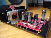
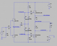
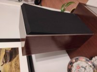
- FAST using my 10F/RS225 Reference speaker (described in another thread) but with the original full range driver removed and replaced with the driver under test. The rear chamber is a tall 3 sided pyramid or "Dagger" stuffed with fiberglass and has very low - almost zero signature and no signs of "boxyness".

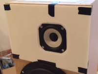
- Drivers under test are fitted with sheets of foam core to permit a flush mounted driver to reduce diffraction in the high frequencies. The offset mounting in a rectangular baffle already reduces the diffraction signifcantly.

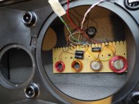
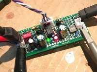
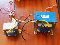
- Source tracks are converted to mono on Audacity and saved as .wav files and then three test tracks are burned into a single track on a CD. A Phillips CD player provides the music source via the headphone outs which allow volume adjustment for the miniDSP which drives two Ybdz TPA3116D2 amps with OSCON cap mod and bootstrap snubber mod. The miniDSP is using a Harsch XO set at 350Hz XO frequency. The *only* adjustment made in miniDSP between drivers is adjustment of the level of the full range to normalize for different sensitivities (typical -1dB to -4dB).

- Sound clips are recorded in stereo in 24bit 96kHz .wav files with a Zoom H4 recorder to microSD card. Files are then processed in Audacity to set consistent volume at -0.5dB peak for Clips 1 and 3, and -1dB for Clip 2, then converted to 320kbit 48kHz sampled mp3 files. Files are renamed with .asc extension to allow large file uploads to diyAudio servers. Please change extension back to .mp3 to listen.

- The answer key to the driver identities is provided to two diyAudio moderators in case anyone ever suspects identity tampering following results.

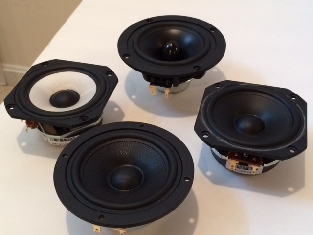
Here are the winners from Rounds 1, 2, and 3:

- Vifa TC9FD18-08 (3.5in paper cone ferrite magnet 8 ohms)
- ScanSpeak 10F/8424G00 (3.5in fiberglass cone Nd magnet 8 ohms)
- Visaton B80 8 ohm (3.5in paper cone Nd magnet 8 ohms)

to this I will add the

- Vifa TG9FD10-08 (3.5in fiberglass cone ferrite magnet 8 ohm version) to allow a fiberglass cone per user requests

And I will also add my secret driver for five total drivers randomly labeled:

A, B, D, E, F (note C is missing because I was going to add two secret drivers but decided against it to keep it lean and fast).

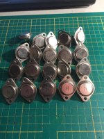
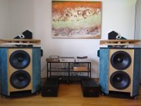
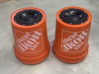
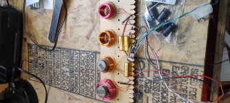
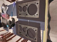
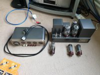
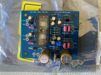
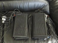
Here is a photo of the 4 drivers (secret one not shown):

502254d1441379545-subjective-blind-comparison-2in-4in-drivers-round-4-round-4-lineup-top.png


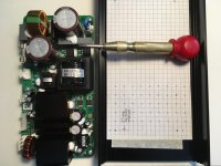
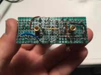
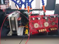
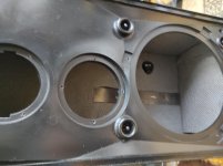
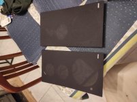
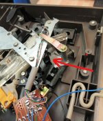
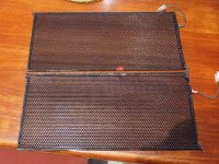
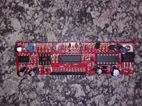
Here is a photo showing detail of the flush mounting rebate with foam core:

502255d1441379545-subjective-blind-comparison-2in-4in-drivers-round-4-round-4-tg9fd-testing-rebate-detail.png


Sound clips to follow... Enjoy and have fun!

Edit (Sept 5, 2015): Adding list of all drivers tested in all 3 rounds leading up to this finale. We are now auditioning and selecting the top 3 (plus 1 that I selected) from a total of 21 drivers. In general, the driver with the flattest response has taken the top spot - so now we are listening to the best of the best in terms of flat frequency response so it is not surprising that it is hard to hear a difference as that is the principal means that our ears differentiate sound voice signature.

Round 1: Winner = TC9FD

1. Vifa TC9FD (3.5in paper cone 8 ohm)
2. Faital Pro 3FE22 (3in paper cone 16 ohm)
3. Dayton Audio RS100-4 (3.5in aluminum cone 4 ohm)
4. Dayton Audio RS100P-4 (3.5inpaper cone 4 ohm)
5. Dayton Audio PS95-8 (3in paper cone 8 ohm)
6. MA CHN-70 (4in paper cone 8 ohm)
7. PRV 5MR450NDY (5in 'midrange' pro audio paper cone 8 ohm)

Round 2: Winner = 10F/8424

8. Vifa TG9FD10-8 (fiberglass cone)
9. Tang Band W4-1320SB (paper cone)
10. Peerless P830986 (aluminum cone)
11. Fostex FF105WK (paper cone)
12. ScanSpeak 10F/8424G00 (fiberglass cone)
13. Mark Audio Alpair A7.3 (silver cone) (aluminum cone)
14. AHE 3in (from Taiwan) (paper cone) http://m.ruten.com.tw/goods/show.php?g=21206258966085

Round 3: Winner = B80

15. SB Accoustics SB65WBAC25-4 (2.5in aluminum cone Nd magnet)
16. Peerless P830983 (2in aluminum cone Nd magnet)
17. Tang Band W3-1364SA (3in bamboo cone Nd magnet)
18. GR Research LGK (3in paper cone ferrite magnet)
19. Mark Audio Alpair A7P (4in paper cone ferrite magnet)
20. Visaton B80 (3.5in paper cone Nd magnet)
21. Visaton FRS5X (8ohm 2in paper cone ferrite magnet)
*REPEAT* Mark Audio Alpair A7.3 (aluminum cone ferrite magnet - previously tested in Round 2)

Edit (Sept. 5, 2015, 2150EDT): Level matched reference sound clips are available here LINK in case you want an easy to compare reference track that is at about the same volume as the test clips.

Edit Sept. 15, 2015: Reveal is here.

Attachments

  • Round-4-Lineup-top.png
    Round-4-Lineup-top.png
    350.9 KB · Views: 8,765
  • Round-4-TG9FD-Testing-Rebate-Detail.png
    Round-4-TG9FD-Testing-Rebate-Detail.png
    318.1 KB · Views: 6,262

Surjan Dogran's Easy Peasy 70v peak-peak Opamp for $1

Member @mediatechnology (Wayne Kirkwood) told me about how to bootstrap ANY opamp using two TO-92 transistors and 4 resistors using Surjan Dogran's Opamp Bootstrap technique first published in Electronic Design, in 1974. I needed an instrumentation opamp that could swing 65v p-p but they don't make opamps that can do that. So I was using a modified Apex FX8 sans the output stage and with some mods to higher voltage transistors etc, it was actually working pretty well. Then I saw this article from 1974 and had to try it. I used a JRC 5534D opamp, normally rated for +/-22v rails. I followed this diagram and added qnty 4 x 10k resistors and a 2N5551 and 2N5401 BJT's to the circuit as shown. That's it.

Few_Extra_Components_741_Op_Amp_For_High_Voltage_Swing_Applications_Dogra_Electronic_Design_April_26_1974_Small.JPG


I then boosted the rails to +/-44v (as 44/2=22v so within safe limit). Here is a photo of my opaamp. I have a couple of extra's features already there from earlier build, including: a Coilcraft 1.2uH inductor with 10R Thiele output network, a 680pF RF lowpass input filter, and a 36pF silver mica cap in parallel with the feedback cap:
attachment.php


And here is the scope shot - it looks fantastic and I am easily driving a clean 70v p-p output and it looks really nice. For 2.68v p-p input I a, getting 70v p-p output. I think that this has got to be perhaps the easiest and most cost-effective way to put your opamp on steroids. Of course, it is not meant for driving low impedance loads - but for cost probably less than $0.25 in parts added to my opamp circuit, I have a bonafide high-swingin' contender here. I bet the THD is now even lower than before:
attachment.php


Anyhow, this worked out really well and hope you all find it useful. Seems like it would be a great ultra-low distortion front end for a higher power output stage.

Attachments

  • Bootstrap-opamp-setup.jpg
    Bootstrap-opamp-setup.jpg
    411.2 KB · Views: 5,573
  • Bootstrap-opamp-scope.jpg
    Bootstrap-opamp-scope.jpg
    353 KB · Views: 3,890

Parting out 2 pairs of Kingsound Kings KS3000

I am parting out 2 pairs of Kings Kingsound electrostatic speakers circa 2009. I had planned on rebuilding them into a slimmer and more spacious frame as the original had the HV wires crammed into to small a space causing breaks and arcing. With Covid, listening opportunities and space have changed and I have decided that I don't have the energy to keep working on these. I am willing to sell separately but obviously would like to clear the lot. I don’t have the frames any more.

The thread I started when I bought them is here. Kingsound King electrostatic Unfortunately I have lost the original pictures.
I had 2 pairs of very similar model Kingsound KS3000 speakers.
Each speaker comprises of 1 pair of Step up transformers, 7 bass panels and 5 tweeter panels.
I measured the transformers with a 1000 Hz tone to check the step up ratio. The crossover is meant to be set at 1000 Hz or so but I used a minidsp 4x10 most of the time. There are seperate HV PS for the bass and tweeter. Bass is 6.5v and tweeter 2.6 v. I have a few spare sets with slightly lower bass voltages. I have modified one pair with a variable DC input voltage.

LF transformer 1: 150
HF transformer 1:75
2 pairs of HV power supplies, 6.5Kv and 2.6kV.
7 bass panels per speaker – 431x221x10mm, The stators alone measure 405x195x1.6mm. DS is 2.5mm. All in working condition. One of my plans was to make my own frames for the woofer panels.
5 tweeter panels per speaker – 300x139x8mm. Stators are slightly smaller. I think the DS is 1.5 from memory. 1 pair is in good working condition but the second pair has a small hole in one of the diaphragms. Doesn’t seem to effect it as they were like that when I got it. A bonus is that in addition to the above, I have a new and unused in original box, set of 10 tweeter panels.

Crossover set at 1000 Hz. Note there are no Inductors involved. I used steep crossovers at 1000 Hz. One pair is bi-ampable and one single input.

There are around 10 bass panels as well where some have holes in the diaphragm or broken wires and a couple are good.

Prices: I expect A$ 300 for a set of step up transformers. Ie 2x HF and 2xLF transformers. A$ 200 for the new set of tweeter panels. Open to offers for the rest.
for reference I have included pictures of the original speakers.
I am based in Perth, Western Australia.

Attachments

  • P5310376.jpg
    P5310376.jpg
    120 KB · Views: 383
  • P5300373.jpg
    P5300373.jpg
    97.7 KB · Views: 375
  • P6080377.jpg
    P6080377.jpg
    258.6 KB · Views: 358
  • P6080368.jpg
    P6080368.jpg
    161.4 KB · Views: 387
  • 20201122_130823-2.jpg
    20201122_130823-2.jpg
    44.6 KB · Views: 370
  • PA310368.jpg
    PA310368.jpg
    51.5 KB · Views: 207
  • tweeters.jpg
    tweeters.jpg
    86.9 KB · Views: 191

Marantz CD63 issue(s)

I have a Marantz CD63 that was playing completely fine. Then, suddenly, the drawer opened on it's own and the drawer motor kept running (squealing away as the belt slipped on). Not only that, the CD motor also kept running at full speed with no CD in place. Both of these things now happen when I turn it on.

I haven't got too deeply into this yet so does anyone have any idea what might cause this. I know it's not a belt issue and I don't think it's a limit switch issue.
Any pointer greatly appreciated.

Thanks.

First Passive 2 way design - incl. Augerpro Waveguide

With the knowledge of having built a few existing proven passive designs and making plenty of my own designs with active DSP crossovers, I decided to give a 2 way passive XO a crack. With the success I've had with augerpros waveguide I mated the Sb26ADC up to the MW19P-4 and here's what I came up with. Looking for any critiques, errors, am I going to eventually blow an amp up. So far its working and sounds pretty good but it would be good to know what to improve if I can. Its worth noting I jimmied the XO up from parts I already had lying around so some compromises were made. Also I didn't nearfield stitch the LF response on the VCAD Measured set but have attached a REW measurement where I did.

Simulated:

2WAY FLRSTND MW19P4 SB26ADCWG REV 8 BUILD STOCK CPTS Six-pack.png
2WAY FLRSTND MW19P4 SB26ADCWG REV 8 BUILD MEASURED CPTS XO-schema-1.png

Measured:

2WAY FLRSTND MW19P4 SB26ADCWG PASSIVE MEASURED GATED 5MS 1M 0-90 HORIZ Six-pack.png
2WAY PASSIVEXO VS MEASURED DRIVERS - LVL ADJUSTED.jpg

Any comments most appreciated. Its been quite the learning curve.

Remote Control for L-Pad...anyone ?

Even though I use Arta etc., at the end I like to finalize cross-over-design of my speakers by ear.

What I would love to do is to build a Infrared-Controlled solution which, as an example, let me switch components of my crossover-network back and forth while music is playing. So, lets assume a L-Pad in front of the tweeter, so a resistor in series and another in parallel. It would be quiet cool to switch between a -1db,-2db, -3db scenario -obviously all with the same impedance and both speakers at the same time, so both resistors gets exchanged by two different other ones in the signal path...like a ladder volume control, but remote controlled.

Has anyone done this ? Ideally based on the back of an existing chinese kit ?

Ideally the same could be used later to switch condensor/coils like going from 12db Linkwitz to 12db Bessel or Butterworth maintaining the cross-over-frequency...

This would for sure elimante pscho-analytical effects when you go from one scenario to the other by soldering back and forth...simply switching while you hear the same piece of music will help to evaluate more consistently.

A visit to gratify the eyes and ears !

Yesterday I went to visit Silvio, for a long time I wanted to know his new business. 🙂
Prior communication, he told me that he had the Denon DL103 capsule that I was looking for, so this time the opportunity was given.
I spent two hours enjoying "those good old days" and came back feeling confused, happy with the purchase, but shocked by the diversity of brands and models of audio equipment that were there.
SP represents McIntosh in Argentina, and had arranged an interview with a very young couple (perhaps they were not) interested in listening to the extraordinary Mc Intosh XR50 cabinet. So I settled at one end of the room, looked down so as not to see where the sound was coming from, and was in awe of the great sound coming from those little cabinets.
Incredible bass! Although also great soundstage, clean and natural voices, soft highs but with great dispersion.
I was also struck by a VPI turntable, the
Avenger Plus. Must see in person! Shocking design and what size!
Well, look at the photos (they will go in several posts) and guess who is who ...... 😀 , we are in the second wave of the pandemic here ....

Attachments

  • IMG_20210622_155657.jpg
    IMG_20210622_155657.jpg
    696.1 KB · Views: 188
  • IMG_20210622_155717.jpg
    IMG_20210622_155717.jpg
    649.9 KB · Views: 195

Far Field measurements of soffit-mount (IB) speaker systems

With normal box speakers of "normal" baffle width, I usually do far field measurements at a distance of 2.5 x baffle width, or 1 meter, depending on circumstances.

With soffit mount speakers, the baffle is basically the entire wall, floor to ceiling. There is no transition from 2-pi to 4-pi. What are the rules, or best practices, for measuring such systems?

Lets assume that this is a dedicated listening environment, such as a control room or mastering room.

j.

FS: Paradise Phonostage PCBs and Extras

Hi all,

I have for sale a complete set of Paradise PCBs.

Inc. Pre reg boards, hackernap boards, Calvin boards, Torroid Boards and PSU boards.

I also have matched quads of the now even rarer authentic and original 2SK170's in a couple of variations, and multiple other transistors.

There are two transformers and four chokes too.

We accumulated a very enviable amount of parts at great expense, but ultimately decided to go in an alternative direction.

Everything other than the chokes are brand new and unused. The chokes were used for 2hrs in another Phonostage.

If there are any technical questions about the bags of still sealed mouser parts, I will have to refer to a third party so my response may be delayed, please keep that in mind if I don't answer your query quickly enough.

Price:

I'll take £300 Inc UK delivery.

I will not split the kit, so please do not ask.

Thanks

94f8569f473d2d244559932496f21639.jpg


2006a1e7c643e5496131c2a9faf51634.jpg


520d862c5760af5a37b0c6c511c28255.jpg


cc58df19c6e6bd0ee9462272a953e58e.jpg


16674cd0a4a5cd06c74acf936f458746.jpg


9a0c2f75edc9efc41518adc329540a7d.jpg


9bbab9652e7d22b83f07a5249e0cd9d2.jpg


cdf6012be906deed05efd4f18140c8a4.jpg


b4ee2f2c36412314d0e65557a7e77e97.jpg

Car Audio Install Question .

Hopefully someone can help me out with this question .

I replaced my factory speakers with the PA style mids and as of most of you know there is no midbass .

I’m wondering if I can use the factory amp to power the factory subwoofer only located under the center counsel so I can get some midbass in the front stage .

If this is possible the next question I have is

I’m using an after market head unit and a older Rockford Fosgate symmetry .

So when using the symmetry the head units volume is set to about 3/4 volume .
So at 3/4 volume in the head unit will this make the factory subwoofer distort or is there something in the factory amp that prevents this ?

Question on rectifying heater supply from AC to DC

Say, you have a power transformer that supplies 6.3VAC to tube heaters. Now you want to rectify the 6.3VAC heater supply from AC to DC, to reduce possible hums. So you add a full-wave bridge rectifier (4 silicon diodes, for example) after the 6.3VAC output from the power transformer. The question is - how much the DC after rectification will be, is it going to be higher than 6.3VDC or lower?

I hope it's higher than 6.3VDC so that we can add some CRC filter after the full-wave bridge rectifier and can still obtain some smoothed DC at 6.3V.

But if it's lower than 6.3VDC, then we can't obtain smoothed 6.3VDC anymore. 🙁

Denon AVR-590 Speaker No Sound Head Phone OK

A Denon AVR-590 has been stop outputting anything to the speakers occasionally. In the past, I applied the "resetting sequence" a few times and it came back. This time, it seems to be gone for good, although I can still get sound from the headphone jack.


This happens to all input sources: AM, FM, DVD, etc. Sometimes I can hear relay(s) clicking for no reason inside. But I am not sure if the click of relays always lead to it having no sound.


This is my first posting in this website. If this is the wrong place, please let me know. A pointer to the right forum for modern stereo repair would be appreciated.


Thank you!
Projects by fanatics, for fanatics
Get answers and advice for everyone wanting to learn the art of audio.
Join the Community
507,706
Members
7,885,121
Messages

Filter

Forum Statistics

Threads
406,077
Messages
7,885,121
Members
507,706
Latest member
thatchacha10