Member @mediatechnology (Wayne Kirkwood) told me about how to bootstrap ANY opamp using two TO-92 transistors and 4 resistors using Surjan Dogran's Opamp Bootstrap technique first published in Electronic Design, in 1974. I needed an instrumentation opamp that could swing 65v p-p but they don't make opamps that can do that. So I was using a modified Apex FX8 sans the output stage and with some mods to higher voltage transistors etc, it was actually working pretty well. Then I saw this article from 1974 and had to try it. I used a JRC 5534D opamp, normally rated for +/-22v rails. I followed this diagram and added qnty 4 x 10k resistors and a 2N5551 and 2N5401 BJT's to the circuit as shown. That's it.

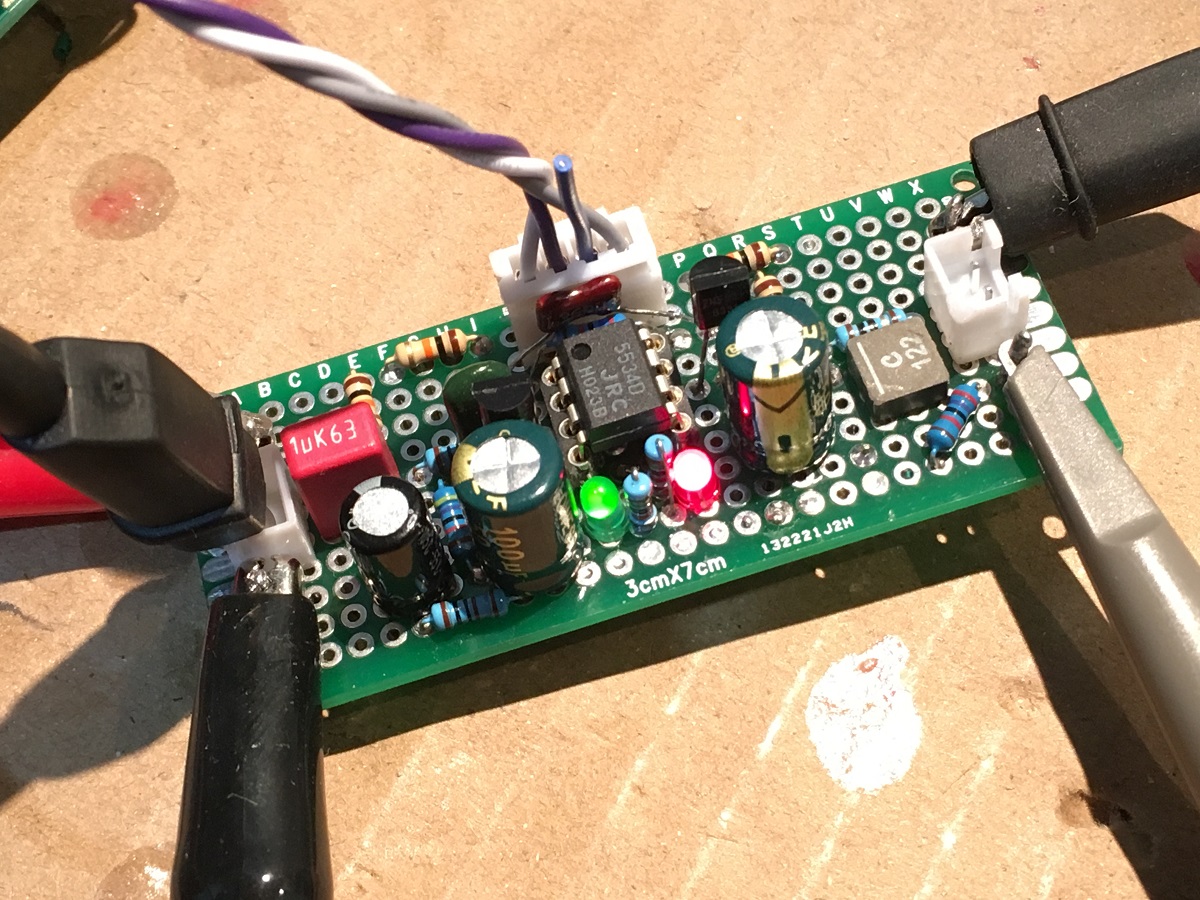
I then boosted the rails to +/-44v (as 44/2=22v so within safe limit). Here is a photo of my opaamp. I have a couple of extra's features already there from earlier build, including: a Coilcraft 1.2uH inductor with 10R Thiele output network, a 680pF RF lowpass input filter, and a 36pF silver mica cap in parallel with the feedback cap:
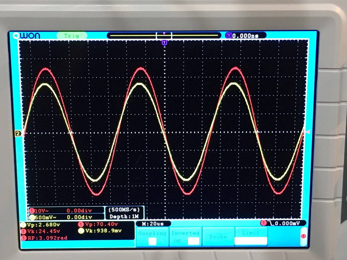
And here is the scope shot - it looks fantastic and I am easily driving a clean 70v p-p output and it looks really nice. For 2.68v p-p input I a, getting 70v p-p output. I think that this has got to be perhaps the easiest and most cost-effective way to put your opamp on steroids. Of course, it is not meant for driving low impedance loads - but for cost probably less than $0.25 in parts added to my opamp circuit, I have a bonafide high-swingin' contender here. I bet the THD is now even lower than before:
Anyhow, this worked out really well and hope you all find it useful. Seems like it would be a great ultra-low distortion front end for a higher power output stage.
I then boosted the rails to +/-44v (as 44/2=22v so within safe limit). Here is a photo of my opaamp. I have a couple of extra's features already there from earlier build, including: a Coilcraft 1.2uH inductor with 10R Thiele output network, a 680pF RF lowpass input filter, and a 36pF silver mica cap in parallel with the feedback cap:
And here is the scope shot - it looks fantastic and I am easily driving a clean 70v p-p output and it looks really nice. For 2.68v p-p input I a, getting 70v p-p output. I think that this has got to be perhaps the easiest and most cost-effective way to put your opamp on steroids. Of course, it is not meant for driving low impedance loads - but for cost probably less than $0.25 in parts added to my opamp circuit, I have a bonafide high-swingin' contender here. I bet the THD is now even lower than before:
Anyhow, this worked out really well and hope you all find it useful. Seems like it would be a great ultra-low distortion front end for a higher power output stage.
Attachments
Last edited:
Thanks for sharing, it's a great idea.
Since the supply voltage across the opamp is constant, it should be ok and perhaps even beneficial to add a decoupling capacitor between V+ and V-.
I actually have a 100nF X7R between the two rails right underneath the IC. You can also see I have two 100uF 50VA rail caps near he Vcc and Vee pins of the opamp. Wayne Kirkwood actually recommends a 470pF to 1nF film cap between base and collector of the bootstrap transistors. I did not use it and seems to work but probably a good idea for enhanced stability.
Thank you! I see the extra steps needed to ensure stability now over operating range.
To ensure that your design meets input common-mode range under all conditions, you must address dc condi- tions, transient conditions, phase rever- sal, and power-up conditions.
Good stuff!
I needed an instrumentation opamp that could swing 65v p-p but they don't make opamps that can do that.
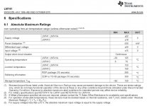
Have a look at the LTC6090 and LTC6090-5 which are 140 volt capable opamps.
Supply Range: ±4.75V to ±70V (140V)
n 0.1Hz to 10Hz Noise: 3.5μVP-P
n Input Bias Current: 50pA Maximum
n Low Offset Voltage: 1.25mV Maximum
n Low Offset Drift: ±5μV/°C Maximum
n CMRR: 130dB Minimum
n Rail-to-Rail Output Stage
n Output Sink and Source: 50mA
n 12MHz Gain Bandwidth Product
n 21V/μs Slew Rate
n 11nV/√Hz Noise Density
Thank you! I see the extra steps needed to ensure stability now over operating range.
Yes, it’s better not to cheat and make things right - just add simple gain stage.


Have a look at the LTC6090 and LTC6090-5 which are 140 volt capable opamps.
Supply Range: ±4.75V to ±70V (140V)
n 0.1Hz to 10Hz Noise: 3.5μVP-P
n Input Bias Current: 50pA Maximum
n Low Offset Voltage: 1.25mV Maximum
n Low Offset Drift: ±5μV/°C Maximum
n CMRR: 130dB Minimum
n Rail-to-Rail Output Stage
n Output Sink and Source: 50mA
n 12MHz Gain Bandwidth Product
n 21V/μs Slew Rate
n 11nV/√Hz Noise Density
Thanks, Mooly. I did not know about these. Will need to get a few to try. Not a bad price at $7.50 ea.
And thanks Abraxalito. Those Tl's look good too. Things have progressed quite abit since I last looked many years ago they were like $50. I guess all they had to do was add a couple of transistors and resistors and diodes internally.
It's still nice to take one of our favorite audio-grade opamps and add large voltage swingnront though.
")
Last edited:
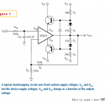
Member @mediatechnology (Wayne Kirkwood) told me about how to bootstrap ANY opamp using two TO-92 transistors and 4 resistors using Surjan Dogran's Opamp Bootstrap technique first published in Electronic Design, in 1974. I needed an instrumentation opamp that could swing 65v p-p but they don't make opamps that can do that. So I was using a modified Apex FX8 sans the output stage and with some mods to higher voltage transistors etc, it was actually working pretty well. Then I saw this article from 1974 and had to try it. I used a JRC 5534D opamp, normally rated for +/-22v rails. I followed this diagram and added qnty 4 x 10k resistors and a 2N5551 and 2N5401 BJT's to the circuit as shown. That's it.
If you replace R1, 4 by a current source and R2, 3 by a zener you can alsmost double the output voltage range.
Jan
So, how is this OK with maximum input voltage?
Hi DUG,
Sorry, not sure what your question is? How +/-22v was exceeded as +/-45v?
If you replace R1, 4 by a current source and R2, 3 by a zener you can alsmost double the output voltage range.
Jan
Thanks, Jan.
I will have to try that. Do you have recommendations for CCS? Could a J113 and a resistor work here?
This would be more along the lines of the schematic in the EDN article from Post #3?
Attachments
Last edited:
Do you have recommendations for CCS?
Pick any:


Could a J113 and a resistor work here?
Yes.
The idea is to get the output of the emitter followers to the required supply for the opamp. If you use, say, 12V zeners then the opamp supply is about +/-12.6, which is nice.
Then if your cs can work up to say 2V across it, your max supply voltage is Vhighsupply - 12.6 - 2. For a Vhighsupply of say 40V that is 25.4V.
If the opamp then allows output swing up to 2.6V below supply, your max output level is 35.4.
Note that the current through the zener and cs + emitter follower base current has to come (partly) from the opamp output, so you may want to minimize it. Use emitter followers with a high gain is a good start.
Edit: in some respects this is a positive feedback loop. If the gain through the outside part is higher than the opamp PSRR, you can get instability. Hence the C from C to B on the emitter follower, to roll off gain at hf.
Jan
Bespav,
Thanks for the nice collection - I have been looking for something like this!
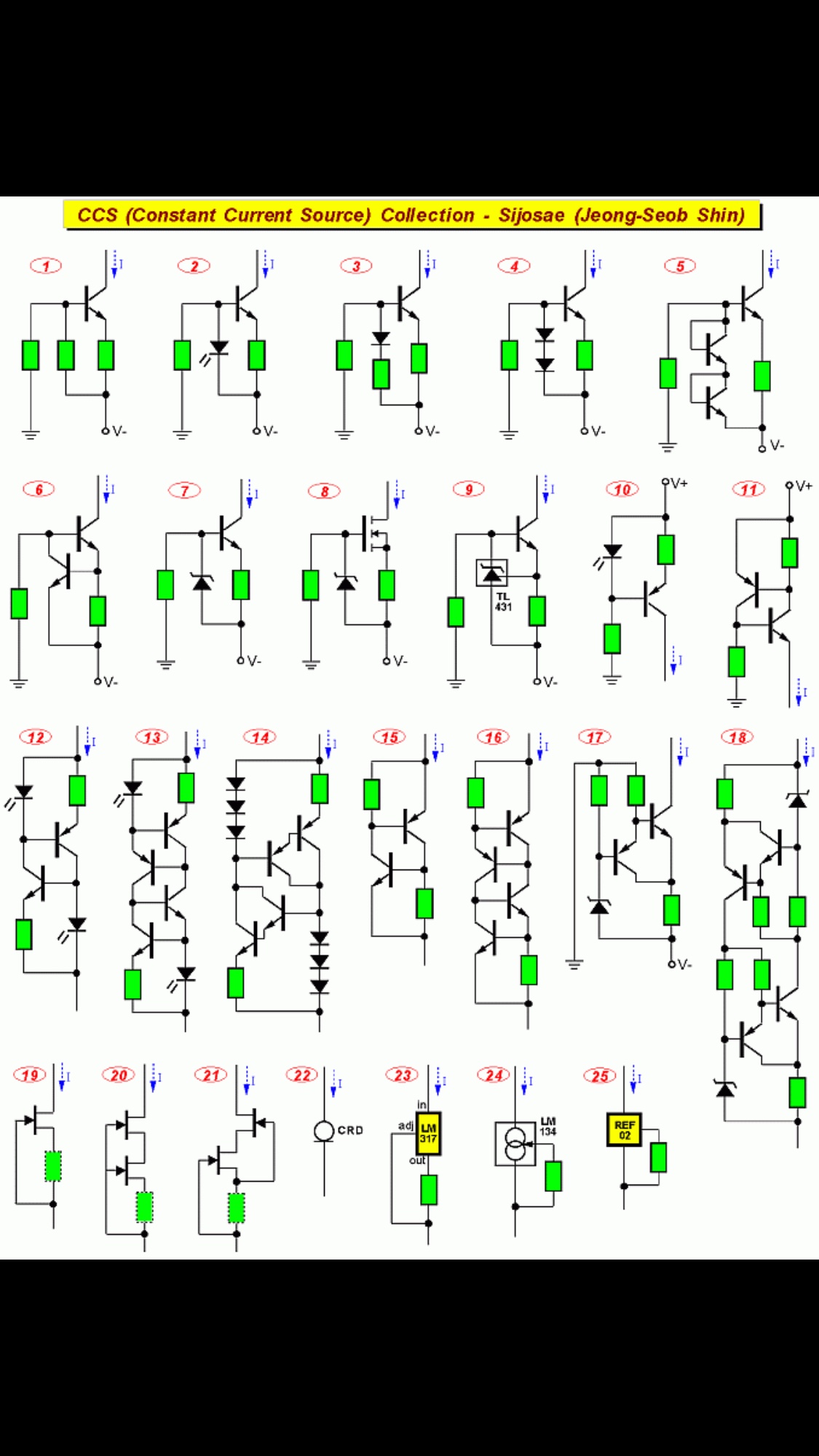
J113 and R is option 19 above.
Be careful - some of these fragments are not CCS's. An easy test: if you change the supply voltage, does the current change? If it does, it aint a CCS.
Jan
Bespav,
Thanks for the nice collection - I have been looking for something like this!
You’re welcome!
Maybe you need this article:
http://waltjung.org/PDFs/Sources_101_P1.pdf
What are the distortion characteristics - do you more or less get the performance of the op-amp itself? The reason I ask is that I'm wondering if this topology be used to build a relatively high gain preamplifier that can swing lots of voltage into 10k-50k input impedance of a unity-gain amplifier?
CharlieLaub,
I know where you are going with this... Can this drive a MoFo or an F4? Yes. I need to run a sim, but my guess is that distortion will be low perhaps even lower than intrinsic opamp by itself. However, it will sound technically perfect like an opamp, but probably lack musicality.
If you hang tight, Aksa and I are working on a nice SE Class A LTP Lender VAS topology preamp for exactly this purpose that can swing 40+ volts p-p with with low THD and nice harmonic profile of descending H2, H3, H4, etc...
Why 40v p-p? Assuming driving a unity gain current buffer amp, that gets you 25w rms into 8ohm speakers.
Sims below are NOT for the bootstrapped opamp. Sorry for the OT but I will make new dedicated thread soon.
Here is a preview 40v p-p into 22kohm load with 2.15v p-p at the source:
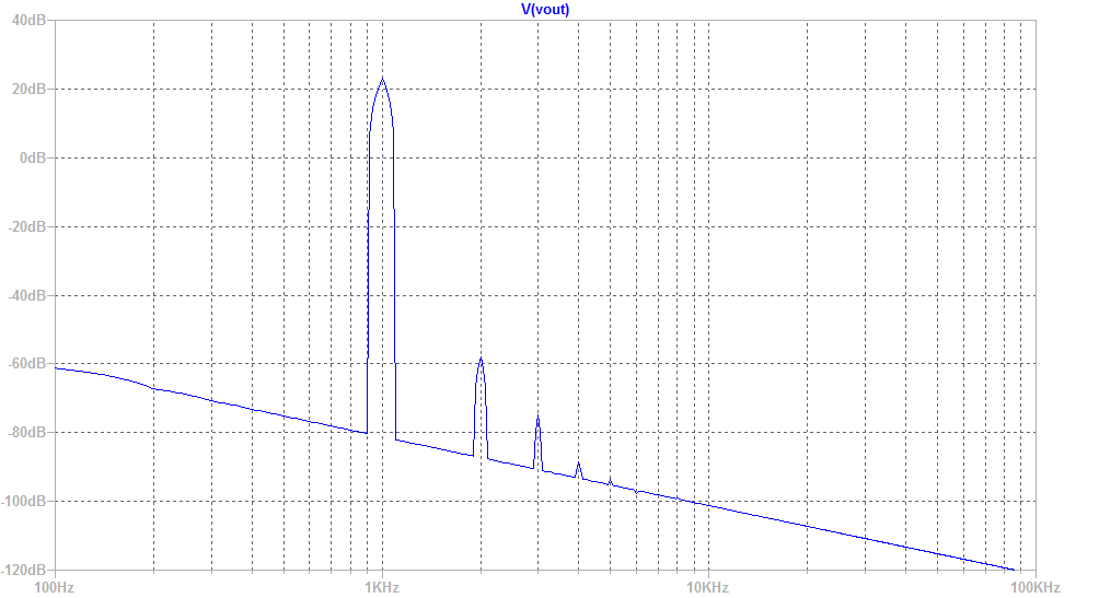
Total Harmonic Distortion: 0.009011%(0.010907%)
For comparison, here is 8v p-p (2.83v rms) into 22kohms:
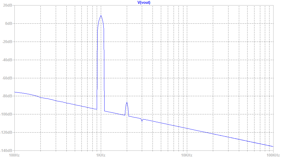
Total Harmonic Distortion: 0.001707%(0.006170%)
I know where you are going with this... Can this drive a MoFo or an F4? Yes. I need to run a sim, but my guess is that distortion will be low perhaps even lower than intrinsic opamp by itself. However, it will sound technically perfect like an opamp, but probably lack musicality.
If you hang tight, Aksa and I are working on a nice SE Class A LTP Lender VAS topology preamp for exactly this purpose that can swing 40+ volts p-p with with low THD and nice harmonic profile of descending H2, H3, H4, etc...
Why 40v p-p? Assuming driving a unity gain current buffer amp, that gets you 25w rms into 8ohm speakers.
Sims below are NOT for the bootstrapped opamp. Sorry for the OT but I will make new dedicated thread soon.
Here is a preview 40v p-p into 22kohm load with 2.15v p-p at the source:
Total Harmonic Distortion: 0.009011%(0.010907%)
For comparison, here is 8v p-p (2.83v rms) into 22kohms:
Total Harmonic Distortion: 0.001707%(0.006170%)
Attachments
Last edited:
- Home
- Amplifiers
- Solid State
- Surjan Dogran's Easy Peasy 70v peak-peak Opamp for $1