Here is the concept put to work:
EZ-Dump: dump your current without really trying
Note that a proper bootstrap will significantly improve the performances (THD) of the opamp it is applied to
EZ-Dump: dump your current without really trying
Note that a proper bootstrap will significantly improve the performances (THD) of the opamp it is applied to
CharlieLaub,
I know where you are going with this... Can this drive a MoFo or an F4? Yes. I need to run a sim, but my guess is that distortion will be low perhaps even lower than intrinsic opamp by itself. However, it will sound technically perfect like an opamp, but probably lack musicality. If you hang tight, Aksa and I are working on a nice SE Class A LTP Lender VAS topology preamp for exactly this purpose that can swing 40+ volts p-p with with low THD and nice harmonic profile of descending H2, H3, H4, etc...
Yep, you read my mind. I am thinking of building the BigMoFo (to drive a compression driver in a 2-way active speaker) and need to boost the voltage swing of the input to that channel, e.g. a preamp stage. This topology seems easy to implement and could fit the bill.
What do you mean by "lack musicality"? If we are throwing around those kind of terms, then I prefer something that is "clinical" over "sweet and musical". So the op-amp based stage seem to fit the bill for me.
I have a thread of voltage-bootstrapped op amp articles here: Bootstrapped Op Amp Articles - Pro Audio Design Forum
I used the technique beginning back in 2006-2007 to eliminate input coupling capacitors in a phantom-tolerant mic preamp input: New: A Direct-Coupled Input-Capacitorless Active Mic Preamp - Pro Audio Design Forum

Input-Capacitorless Preamp Overall Block Diagram
The "Flying Rail" common mode servo using the voltage-bootstrapped op amp is a key circuit element for the Input-Capacitorless mic preamp.

Input-Capacitorless Preamp Feed-Forward Common Mode Servo With Bootstrapped Flying Rail Supply
The above circuit is not suitable for audio and is optimized to "bracket" the microphone's common mode DC voltage, Vcm, with +/-15V.
The input rails are +66 and -18V.
I used the technique beginning back in 2006-2007 to eliminate input coupling capacitors in a phantom-tolerant mic preamp input: New: A Direct-Coupled Input-Capacitorless Active Mic Preamp - Pro Audio Design Forum
Input-Capacitorless Preamp Overall Block Diagram
The "Flying Rail" common mode servo using the voltage-bootstrapped op amp is a key circuit element for the Input-Capacitorless mic preamp.
Input-Capacitorless Preamp Feed-Forward Common Mode Servo With Bootstrapped Flying Rail Supply
The above circuit is not suitable for audio and is optimized to "bracket" the microphone's common mode DC voltage, Vcm, with +/-15V.
The input rails are +66 and -18V.
What do you mean by "lack musicality"? If we are throwing around those kind of terms, then I prefer something that is "clinical" over "sweet and musical". So the op-amp based stage seem to fit the bill for me.
Well, I'm glad this bootstrap thing can probably work for you to boost the drive to a CD. It will probably sound very nice and clinical as you say 🙂
Although the profile I posted above isn't too shabby at tens of ppm THD for 8v p-p with a sweet profile.
MCI/Sony brought the voltage-bootstrapped "swinging op amp" circuit into the audio realm in 1979 to replace an obsoleted Harris HV op amp, the HA-2645, used in the JH-500 console.
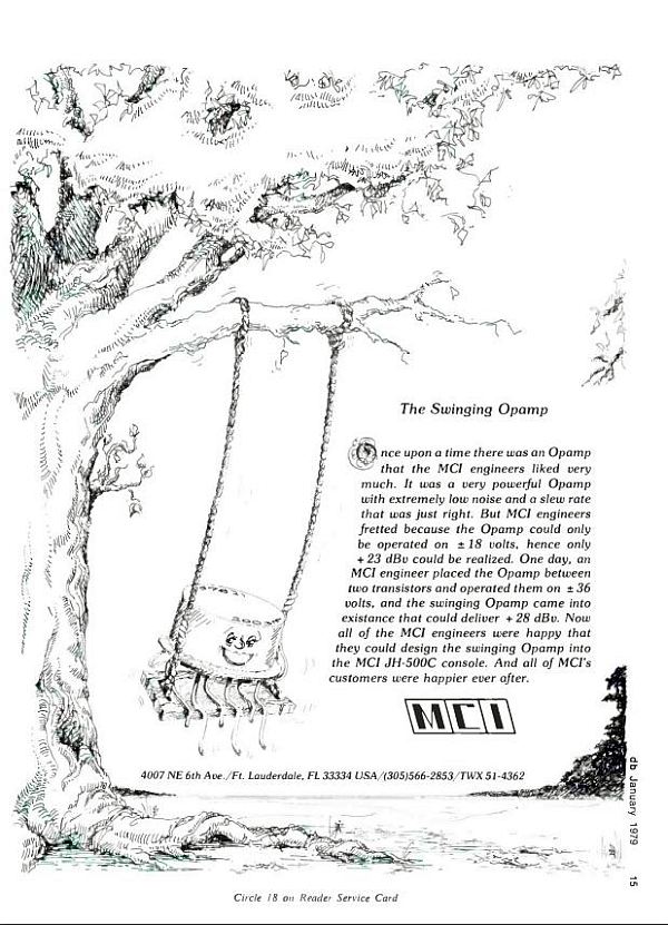
MCI Swinging Op Amp Ad dB Magazine January 1979.
The distortion performance of the circuit is usually limited by the op amp's output current capability.
Hundreds, if not thousands, of hits have been cut on the MCI JH-500C series consoles.
MCI Swinging Op Amp Ad dB Magazine January 1979.
The distortion performance of the circuit is usually limited by the op amp's output current capability.
Hundreds, if not thousands, of hits have been cut on the MCI JH-500C series consoles.
You mean something like this?

Looks like an amazing piece of analog audio engineering. What did these consoles cost new?
Looks like an amazing piece of analog audio engineering. What did these consoles cost new?
Last edited:
That looks to be a JH-532D with Plasma Light Meters so about $100K in 1982 dollars. Probably had automation so maybe more. See: MCI - Designer and Manufacturer of the Professional Audio Recording Equipment
So, how is this OK with maximum input voltage?
The input must remain inside the chip rails.
But the 1974 plan clearly violates today's 36V spec for '741 (and most others). This used to be called "40V process" and back in the day I remember a lot of people pushing to and past 40V. This often works, for years or days. 43.8V is very brave.
The inverting connection with +in grounded imposes other limits. The noninverting connection may be better.
$100k in 1980 is like $500k today? What does a mixing console need a 70v swing opamp for? To drive the 32 ch of EQ banks?
I think this experiment was a real eye opener for me. I'll never look at a lowly opamp in the same way again, knowing it's about 2 (puny TO92) transistors shy of being transformed into a giant.
I think this experiment was a real eye opener for me. I'll never look at a lowly opamp in the same way again, knowing it's about 2 (puny TO92) transistors shy of being transformed into a giant.
....What does a mixing console need a 70v swing opamp for....
That's in the MCI ad. Some installations expect +28dBv, which is 25Vrms or 71V p-p. There are various ways to arrive at this requirement; but note that "long lines" (over 100' 30m) were often driven through a 6dB pad to isolate impedance quirks. So +4dBm@600r (nominal studio level), plus 18dB for headroom, plus 6dB pad, is +28dBm or 20Vrms. Round-up a couple dB, +28dBv.
Modern practice is two opamps push-pull which will deliver about 21Vrms into a balanced load. And use of 6dB pads is fading as systems shrank from national networks and giant buildings, to small buildings (now bedrooms).
What PRR said.
In addition you aren't actually able to get +28 dBu out of the MCI Swinging Op Amp into 600Ω since the "2003," a metal 5534, provides the only available output current. Their +28 number is likely with a >2KΩ internal load.
For an identical amount of headroom the Swinging Op Amp allows the console's internal levels to be run about 6 dB hotter. Instead of being normalized to -2 it can remain +4 and still have 20-24 dB headroom.
The ADI Grayson/King article discusses input voltage limitations and latch-up considerations when using the voltage-bootstrapped op amp. Bootstrapped Op Amp Articles - Pro Audio Design Forum
Quote:
Originally Posted by DUG View Post
So, how is this OK with maximum input voltage?
Maximum input voltage +/- 15V (from data sheet)
Non-inveting input is at gnd. (from schematic)
With the output swing to +/- 35V the opamp supplies swing between 4.5 and 39.5. (and -4.5 and -39.5) (from a quick LTSPICE simulation)
The midpoint between 39.5 and -4.5 is about 17V.
Would this mid point between the supplies be considered what the non-inverting input is referenced?
And to what the 15V maximum rating is referenced to?
Sorry PRR, missed your post:
Sort of what I was trying to get at.
Originally Posted by DUG View Post
So, how is this OK with maximum input voltage?
Hi DUG,
Sorry, not sure what your question is? How +/-22v was exceeded as +/-45v?
Maximum input voltage +/- 15V (from data sheet)
Non-inveting input is at gnd. (from schematic)
With the output swing to +/- 35V the opamp supplies swing between 4.5 and 39.5. (and -4.5 and -39.5) (from a quick LTSPICE simulation)
The midpoint between 39.5 and -4.5 is about 17V.
Would this mid point between the supplies be considered what the non-inverting input is referenced?
And to what the 15V maximum rating is referenced to?
Sorry PRR, missed your post:
The input must remain inside the chip rails.
But the 1974 plan clearly violates today's 36V spec for '741 (and most others). This used to be called "40V process" and back in the day I remember a lot of people pushing to and past 40V. This often works, for years or days. 43.8V is very brave.
The inverting connection with +in grounded imposes other limits. The noninverting connection may be better.
Sort of what I was trying to get at.
Last edited:
I think the thing to check is to make sure the opamp rails are never exceeded internally. This can be done by measuring the Vcc and Vee pins once bootstrap is in place. For my case, for example, the JRC opamp is rated for +/-22v rails. With a 1:2 voltage divider network a maximum of +/-44v can be safely applied. I used a DMM to measure voltage at the pins and indeed verified it was only +/-22v. Luckily, I have an adjustable DC-DC dual rail step up converter so I could dial in the max allowable external rail voltage rather than work wirh hard set PSU voltages. Some opamps are only rated +/18v so in that case, with a 1:2 divide the max external rails would be +/-36v.
Not all 741s have +/-18V supply maximums.
The 741 and 741A "industrial" temperature range parts have +/-22V absolute maximum Vcc/Vee ratings. The 741C, "commercial" has +/-18V absolute maximum. A careful look at Dogra's original schematic shows the use of the µA741. No "C" at the end.
According to the TI datasheet the maximum input voltage is rated at +/-15V or equal to Vcc and Vee if they are lower. The TI datasheet does not explicitly specify at what Vcc and Vee the +/-15V limit applies to. With +/-22V rails it might still be equal to Vcc and Vee. The first two bullet points read "overload protection on input and output" and "no latch-up when the common mode input range is exceeded."
But, other than for argument, why do the limits of a 741C matter as it relates to using this circuit in audio applications? It doesn't.
Look at the 5534. The NJM5534 has +/-22V absolute maximum for supplies and input common mode range.
An analysis of input common mode range limits of this circuit are in the Grayson King article referenced in this thread at least 2-3 times already. For those interested in avoiding excessive common mode input voltages in this circuit please click the link.
Last edited:
There's also Dmitri's edn article about bootstrapped composites.
You'll want to Google for it, as the original edn article is now missing the images.
You'll want to Google for it, as the original edn article is now missing the images.
That's a huge problem with the EDN archives.
I have Dimitri's article in hardcopy and when I get the chance will scan it. The distortion reduction was significant. Self also writes about similar bootstrapping for the TL07X in Small Signal Design.
Just revisited the MCI "swinging op amp" schematic and it looks like their NE5534s "2003" were running at about +/-20.7 V. The bulk rails are +/-36V.
Last edited:
Yes, they definitely help with CM/source impedance distortion. It's good to mind that a lot of very good general purpose opamps (opa164x series comes immediately to mind) are on dielectric isolation (DI) processes, which reduces a lot of the benefit of bootstrapping.
But there's a lot more flexibility with bootstrapping. Everything is a compromise, so it's good to have these tools at our disposal. 🙂
Edit to add: apologies to Dimitry Danyuk for misspelling his name.
But there's a lot more flexibility with bootstrapping. Everything is a compromise, so it's good to have these tools at our disposal. 🙂
Edit to add: apologies to Dimitry Danyuk for misspelling his name.
Thanks for posting, killer idea.
FWIW I am into Musical Instrument amplification, and often met, in the 80´s, the very popular Polytone amplifiers, some of which used the infamous LM391 power amp driver chip ...
which had to swing +/-33V (66Vpp) and of course was all but unavailable here.
Spares could be ordered by snail mail (no Internet , EBay, Amazon, etc. way back then), which might mean30 to 90 day delays.
So in the interim, for anxious Musicians (is there any other kind? 😉 ) I made a small daughterboard, powered by a 741 and dead bug mounted to original 391 approppriate holes.
In practice, about 20% 741 could swing the needed amount, so I tried a few until I found one that did, and out the amp went, no guarantee or promises attached.
AFAIK all of them worked normally, at least no one came back dead for re-repair.
A few got the proper 391 (in due time) , surprisingly most worked flawlessly for years with selected 741 .
Selection was very easy, I just plugged one after another into the socket and drove amp to clipping, without load, so as to maximize voltage stress, then loaded amp to check it met current needs.
Worked like charm.
FWIW I am into Musical Instrument amplification, and often met, in the 80´s, the very popular Polytone amplifiers, some of which used the infamous LM391 power amp driver chip ...
An externally hosted image should be here but it was not working when we last tested it.
which had to swing +/-33V (66Vpp) and of course was all but unavailable here.
Spares could be ordered by snail mail (no Internet , EBay, Amazon, etc. way back then), which might mean30 to 90 day delays.
So in the interim, for anxious Musicians (is there any other kind? 😉 ) I made a small daughterboard, powered by a 741 and dead bug mounted to original 391 approppriate holes.
In practice, about 20% 741 could swing the needed amount, so I tried a few until I found one that did, and out the amp went, no guarantee or promises attached.
AFAIK all of them worked normally, at least no one came back dead for re-repair.
A few got the proper 391 (in due time) , surprisingly most worked flawlessly for years with selected 741 .
Selection was very easy, I just plugged one after another into the socket and drove amp to clipping, without load, so as to maximize voltage stress, then loaded amp to check it met current needs.
Worked like charm.
JMFahey,
Thanks for sharing that story. I guess trial and error is one way to find a working chip - assuming the pile you have had a distribution and were not all presorted.
So those hot rodded 741's could drive the output transistors as shown in the diagram?
Thanks for sharing that story. I guess trial and error is one way to find a working chip - assuming the pile you have had a distribution and were not all presorted.
So those hot rodded 741's could drive the output transistors as shown in the diagram?
I wonder if this new audio opamp is a good candidate for bootstrapping? Perhaps use high current (1amp) SOT223 MBM5401/5551’s
http://www.ti.com/lit/ds/symlink/opa1622.pdf
Edit: a darn nice measuring opamp with -130dB THD for 50mW into 30ohms but it is dual channel so cannot be bootstrapped.
http://www.ti.com/lit/ds/symlink/opa1622.pdf
Edit: a darn nice measuring opamp with -130dB THD for 50mW into 30ohms but it is dual channel so cannot be bootstrapped.
Last edited:
- Home
- Amplifiers
- Solid State
- Surjan Dogran's Easy Peasy 70v peak-peak Opamp for $1