Looking for a data sheet for DNA Sequence Midrange

Hello,

I'm having trouble identifying the part used in the DNA Sequence for midrange reproduction.

From DNA Sequence Speakers dipole open baffle woofer high efficiency point source array midrange tweeter treble loudspeaker

"5.75 inch polypropylene sandwich cone midranges made in Denmark - possibly the best midrange driver ever made!"

I bought 25 of them a few years back, and I'm trying to build with them, but having trouble figuring out the right crossover point and enclosure arrangement.

The inductance is vanishingly low, and the transient response is very good, and the SPL is around 92dB if I recall correctly.

Thanks in advance for any help.

BK Precision 2120 gone blurry

I bought a used BK 2120 scope about 7 months ago, and its been pretty faithful actually up until this afternoon. I know how to use it and have been using it on average about an hour per day since purchase.

The trace line for both channels just today quadrupled in height. Focus cannot get the trace line as sharp as it was even just this morning. Nothing has changed at all afaik but then again dealing with old equipment. The scope still works otherwise but very annoying not seeing that sharp trace.

I opened it up but everything seems very clean inside.

Foreign object to me. There are no pots for focus fine-tune adjustment within either.

Anybody know how I might service this?

freeDSP V2.0 (ADAU1452) developement thread

If you don't feel like searching the thread..

PiDSP is on GitHub:
Sourcefiles[/QUOTE]

There is also manual:
PiDSP manual

Final(hopefully 😀) version is under way. You can watch the progress in development branch in Git repo.

I'm also pondering about having a batch of PiDSP boards profesionality made.
If you are interested, drop me a PM.


----------------------------------------------------------
----------------------------------------------------------
Hello everybody 🙂,
few weeks ago I've discovered the freedsp project and found it to be very interesting... but the ADAU1452 seems so much more potent dsp.
So I got in touch with the creators and joined the team with focus on new version with ADAU1452. I've been pondering about it for some time now, reading datasheets, researching, playing with possibilities etc.
Now it's time to open development thread and ask you about your opinion, feedback, and ideas, so we can make the next version as good as we can.


Flood of questions and ideas follows..

The general idea:
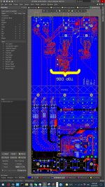
DSP, DAC, PSU - each on its own separate board, connected via wires, maybe backplane. ADC is not in my scope at this moment
PCB width 100mm - enclosures available, length 80mm(half eurocard) or 100mm, we will see.
Smaller builds could fit into extruded enclosure (hammond,fischer), bigger in rack
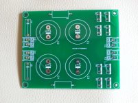
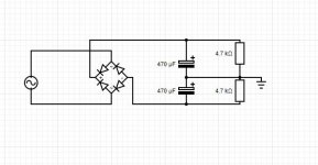
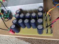
PSU board:
talema 70000K +- 15v for opamps and 48V(via voltage doubler) for phantom - no reason not to add it. will be useful with possible ADC board
Another transformer for digital part, maybe with double secondary - second winding for analog circuitry - PLL, DAC ref. etc.
I haven't made my mind about it yet. Any suggestions?
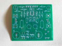
DAC
Stacked TRS 6,3mm - only way to fit 8ch to 100mm wide PCB, 8ch - why not 4x2ch? Big, expensive, I'd like the project to be accessible, and I like KISS principle. I've narrowed down DAC choices to following:
PCM1690 - cheap, available, even got samples somewhere...
AK4358 - comparable with PCM, number-wise
dual AK4413EQ, higher performing pin compatible alternative available AK4414EQ - really nice spec.
AK4458 - new part, isn't available yet, would be nice to use new stuff in the design though. I'll try to get samples.
Opinions (and experiences) about/with DAC chips highly welcomed. My life is too short to try everyone of them, so in the end I'll just pick one and go with it,If you have something to say about them, please do.

Why no ESS stuff? I'd like you to be able to buy all necessary parts at usual outfits (digikey,farnell,mouser...).
Yes, you can buy Sabre in single qty, no problem, but the shipping is prohibitive. And world is full of sabre dacs.
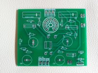
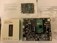
DSP board.
All IO should be brought out. Clocks on UFL connectors, others on 2.54 headers, signal/ground, signal/ground... SPDIF on BNC.
We could add MCLK input, its just a few additional parts and might be useful for some.
Number of I2s lines is limited, 4in, 4out more channels is accessible via TDM. I'm considering providing isolation on I2S lines, so you could use the board directly with BBB as a source.
Would be nice if one could plug BBB directly into the board - you even could program the dsp with it.


I believe it's enough for a first post. Opinions, advices, questions?

At this point it's just bunch of ideas, in the end it could be single board with XLR outputs.... Nothing is set yet... well probably DSP, oscillator, and LDO for PLL are set 😀 ... What I meant is if you think that single board(or XLR, or DAC XYZ) solution is better, say it and add why you think so 😉

Thanks for reading

Pitrsek


P.S.😛lease feel free to notify my about my spelling/grammar mistakes via PM.TY.

Possible to do feedback from before OPT on PP amps?

OK, long shot here. Taking FB to the VAS from the primary side of the OPT (output tube plate) is a simple matter in SE amps but is there a way to take feedback from the primary side to the VAS in a PP amp? If you take it from just one output tube it might be OK for normal signals but I am thinking that things would go completely nuts when there is an overload or even class AB operation. Reasonable assumption? Any clever tricks or just bite the bullet and buy a scope?

sherwood s 6020 CP has no audio output?

Hello! I'm trying to troubleshoot my preamp, one day it was working fine and the next day it had no sound! I'm very inexperienced with this sort of thing, and this preamp is pretty old, so google wasn't much help. I've checked the fuse, cables, and plugs, and I'm about to take it apart to clean the inside. Hoping there's a simple fix that I'm missing.

Denon AVRX5200W/6200W

Hi everyone!

Troubleshooting SMPS with output voltage fluctuation from 4.8V to 5.0V, spikes to 5.2V and back to 4.8 every 2-3 seconds.

Replaced with brand new: both optocouplers U6501/02, rectifier D6515, U6503 IC.
Primary voltage is stable 160V on C6506.
T6501 secondary side is stable AC voltage.
Diodes tested OK. Caps OK. Resistors OK.
Suspect D6524, but not sure....🙁

Any help is greatly appreciated!

Attachments

DIY amplifier: OPA 1611 + Bipolar transistor

Hello,
I am not an electronic engineer and my english is poor.
Sorry for my mistakes.

I work on this amplifier for a few month with MicroCap 12.
Here is the schematic, distortion with 1Watt output and phase diagram.

What is your opinion and your comments?

The power supply will be a SMPS from HYPEX + - 64V

Attachments

  • schema.jpg
    schema.jpg
    191.9 KB · Views: 679
  • Distortion-1W.jpg
    Distortion-1W.jpg
    250.1 KB · Views: 575
  • Phase.jpg
    Phase.jpg
    340.9 KB · Views: 536

Single Ended Triode Class A2 Driver Design

One approach to gain more output power for single ended triode amplifiers is to drive the output tube to positive grid for class A2 operation. I found two different circuits on the Internet. One uses 12AT7 and the other uses IRF610.

Can someone with more experience comments on these two approaches?

The 12AT7 seems to be biased quite low. I am not sure it can deliver 4 mA for the 6S4A tube to operate at full A2. Can I increase the bias or change the tube to something like 12AU7 or 5687?

The IRF610 for 4P1S (4P1L), on the other hand, was biased at 42 mA. It looks like good enough to drive the 4P1L. However, what are the design criteria for this MOSFET? Is IRF610 linear enough? Are there better new MOSFET for this application?

Attachments

  • 6S4A SET Class A2.jpg
    6S4A SET Class A2.jpg
    86.2 KB · Views: 1,030
  • 4P1L SET Class A2.jpg
    4P1L SET Class A2.jpg
    88.9 KB · Views: 945

Transformer took a hit

Hi everybody !


I'm new here. I didn't find a place te present myself, so i do it here.


I'm a jazz/rock and so on guitar player from Belgium, always playing on tube amps for years and years.


One of my amp took some rock and roll on the side, and the transformer took a hit. on the side. (See picture below.)


IMG_1168.jpg


My questions are the following : do you think the transformer is broken ? If not sure, do you think i can try to switch the amp on without damaging anything else than the transformer if it's broken ? (NB : the amp wasn't switched on when it took that hit and has never been switched on since.)


I don't have much of a peny to ask to a technician to repare it right now, but i still would like to play so hit singles if it's still working.


Thanks a lot in advance for your time and help.


Best everything you like,


Y.

Locating holes for tube sockets

Apologies if I’m brain dead and this turns out to be a stupid question. I’m building a tube amp and need to punch holes in the metal top of the chassis for 9 pin tube sockets. How does one precisely locate the holes? I have two PCB’s with two nine pin tube sockets on each board. I can’t just lay the sockets on the metal and trace around them because the PCB’s are in the way. If I lay the sockets on the metal without the boards to locate them, then they won’t line up when attaching the sockets to the PCB’s. I’ve been pondering this for weeks and can’t envision a solution. Any help will be greatly appreciated.

GU-50 screen and suppressor grid resistors

Hi guys,


currently I'm designing a class AB2 PP amplifier working with two pairs of GU-50's. The operating point will be the one in the rightmost column at page 9 of the Telefunken EL 152 datasheet. My PSU only provides 290 Vdc for the screen grid supply, though. In order to increase efficiency by decreasing the tubes' internal plate resistance, the supressor grids will be fed from +12.6 Vdc.


The datasheet doesn't read values for the screen grid resistors and especially not for the suppressor resistors, as this isn't a very common way to go. Which resistor values would you recommend, please?


Best regards!

Whats the advantages of "Distributed Port" enlosure

Hello Folks,

I have an old and deteriorated bass reflex speaker with 8 inch driver tuned in 50hz and want to make a new enclosure

instead of make an exact copy the box i want to try some experiments

i want to try to make the same box with same tunning but instead of use a single port i want to use multiple ports like the project i saw in this old article


my question-

whats the benefits and disvantages of the distributed port enclosure compared to a single port bass reflex and why they arent so popular

Attachments

  • 1.png
    1.png
    291.1 KB · Views: 457

Need a little help with crossover design

I'm new to speaker building and I have two main questions, is it advisable to do a series parallel crossover in a 4 way speaker cabinet, and is this a good layout for my crossover in general, I'm not quite sure of the inductor layout. Also, I know the Caps aren't optimal but they were what I could afford at this time (I will be replacing them later).

Attachments

  • 0.jpg
    0.jpg
    59.4 KB · Views: 101

FS: some various PCB boards

Hello.

I have some pcb boards as leftovers of projects I already made.
In particular they are respectively:


2 "DC trap" boards
2 Boards for low voltage headphone amplifier with ECC82
3 Boards for s.s. "Canamp clone" headphone amplifier
3 Dual PSU with CRC filter boards

2 LM317 (+CRC filter) boards


See attached images. If someone's interested can write here or MP.

Thanks

Attachments

  • DCtrap.jpg
    DCtrap.jpg
    557.3 KB · Views: 479
  • ECC82-ha.jpg
    ECC82-ha.jpg
    679 KB · Views: 475
  • CAclone.jpg
    CAclone.jpg
    673.6 KB · Views: 465
  • DualPSU.jpg
    DualPSU.jpg
    538.4 KB · Views: 468
  • LM317+filter.jpg
    LM317+filter.jpg
    665.6 KB · Views: 460

My built on Dual Feedback(Pre&Post) with GanFET

My Class D with GanFET & LLC

I am working on a new Class D with Ganfet. Heres what I am intending to have it in the build:

LLC Switching @ 200kHz @ full load with PC95, PQ5050 using minimal gain to reduce switching noise during light load.

Target Operating Voltage: +/- 50Vdc
1Mhz Operation.
Paralleled EPC2207
Bridged Mode
Balanced/Unbalanced input.
DC Offset protection with MosFETs & Optocoupler as switch
Protection: OTP, OCP
All connectors are PCB Mount.
Common Chokes are used in all rails.

Cant wait to have this powered up!

And I name it as TOP DOG. 😀😀😀

Attachments

  • 600w.jpg
    600w.jpg
    775.9 KB · Views: 431

Help to choose a 8" Woofer for a sealed box.

Hello,
I am currently in the market for a 8" woofer to use in a 4 ways active monitor design and looking for some advices.

It will be used in a sealed box from 80Hz to 500/650Hz with a Morel EM 1308 so i need it fairly flat that range, low distortion is also a requirement. As for the Xover itself i'm using a dsp so fine tunning isn't an issue.
I don't really care about sensitivity either as my listening spot is about 1.5m.
For the material i'd prefer (treated)paper or composites as i'm not a fan of aluminium (my current woofers are alu i know their pros and cons).
And for the price per unit i'd like to keep it under 120€/130$.

After some research i had some candidates like:
-SEAS Prestige CA22RNY SEAS H1471-08 CA22RNY - 8" Subwoofer
-Peerless 830868 Nomex Peerless by Tymphany HDS-P830869 - 8" Woofer
But i'm open to any suggestions.
Thanks in advance.

Split rail from transformer with no center tap

Hi Everyone,

I have a step-down toriod transformer. Really nice quality, USA made.

Its 240v to 110V, 1000W

So long as the load is equal on both rails this should work to split the rails?

the load an amp puts on the rails should be symmetric right?

please ignore part values, its just for an example.

It just seems like I'm missing something.....

Attachments

  • psu.JPG
    psu.JPG
    36.2 KB · Views: 400

The next best thing to 2SK389 / 2SJ109 ?

Just as everyone else, I am running down on my reserve of 2SK389/2SJ109s, and am looking for the best possible substitute.

The LSK389 is only available in N-JFET, and is not pin compatible. So for me no solution.

The most obvious solution is to use still available 2SK170/2SJ74 matched pairs. If you have a large pool, you can get them even better matched than the 2SK389/2SJ74 (spec at 3% match).

http://www.diyaudio.com/forums/showthread.php?postid=1689279#post1689279

But how about thermal coupling ?

You can glue them on the flat surfaces with silver epoxy, but you mess up the pin compatiblity to the duals.

So this is my solution. 😉

It has a factor of 3 more thermal contact surfaces than just gluing on the flat surface, for much improved thermal coupling, and is still small enough to fit in most applications, with a footprint of 16x8mm.

The heatsink helps to increase thermal insertia and hence thermal stability, and keep the temperature a bit lower than without.

They are not extrusions (with a minimum order of 1 ton in weight), but rather CNC wire-cut from solid. This also explains the rough surface finish, which is an added advantage as it increase surface area for heat exchange.


Merry Christmas,
Patrick

Attachments

  • dual jfet.jpg
    dual jfet.jpg
    90.3 KB · Views: 9,705

Daphile Confirmed working USB Dongles

USB WiFi dongles confirmed working


COMFAST CF - WU735P
D-Link DWA-125 Wireless N 150 USB Adapter
D-Link DWA-182 Wireless AC 1200 Dual Band Wifi USB Adapter
Edimax AC600 Wi-Fi Dual-Band Directional High Gain USB Adapter
TP-Link TL-WN722N 150Mbps High Gain Wireless USB Adapter
TP-LINK TL-WDN3200 N600 Wireless Dual-Band USB Adapter
TP-Link TL-WN725N 150Mbps Wireless N Nano USB Adapter


Direct Ethernet(PC to PC, PC to Laptop, Laptop to PC or Laptop to Laptop) settings if you can't connect via WiFi a big thanks to Indiglo for these


Daphile Settings

IP address: 10.0.0.60
Subnet mask: 255.255.255.0
Router: leave blank or 0.0.0.0
DNS servers: 1.1.1.1
Search domains: 0.0.0.0

PC Settings
IP address: 10.0.0.61
Subnet mask: 255.255.255.0
Default gateway: leave blank
DNS servers
Prefered DNS server 1.1.1.1
Alternate DNS server: 1.0.0.1


if you know of any more please leave a comment with the name and i will update the list

How might one set hornresp to examine the "variovent" case?

Here's a try using a Klipsch Heresy I with K22 spec woofer.

I may have not damped the port enough.

The Z peak, normally in the 65Hz region is flattened. Some peaking in the response curve shows (as does significant port output)

Attachments

  • Heresy with leaky vent.jpg
    Heresy with leaky vent.jpg
    340.6 KB · Views: 164
  • Heresy Variovent Peaking.jpg
    Heresy Variovent Peaking.jpg
    463 KB · Views: 160

Simple Speaker Protection

Hello,
Maybe some people on here will be able to answer this:
I'm looking to construct a Simple Speaker Protection Circuit using 2 x Back to Back Electrolytic Capacitors. To get reasonable Low frequency Response using a 12" 8 Ohm Driver, - (looking at commercial designs) - I assume that I will be needing a Capacitance Value of at least 2-3000 Microfarads to go in series with the Speaker Output. My Power Amplifiers run 60 volt Plus and Minus Rails, so I was thinking that 2 x 6800uF Capacitors connected Back to Back with a Voltage Rating of 40 Volts would be adequate. Somewhere else suggested using a Diode connected across each capacitor, with the + of the diode connected to the + of each capacitor would work better, to do with keeping each capacitor formed. At the moment, You cannot get Bi-Polar Caps with more than 2,200 uF at 25 Volts.
Here, I'm trying to get away from the idea of Isolation Relays or Series Forward Biassed Power Fets, because all of this can still fail. I'm looking to transfer no more than 50Watts of RMS Power, the rating of the drivers.
I'm sure that with everyone's vast experience on here, someone will know the answer! Thanks, and Kindest Regards - Telnet100

Help with 2nd Order High Pass Filter

Building speaker cabinets I can do.
Building a crossover? Uhhh....

I'm building a pro audio cabinet. But the final design was just too big. I had to downsize for portability and the trick was that I would need a high pass filter for this box.

BassBox Pro Tech Support is telling me I need this:
What you need is an active 2nd-order high-pass EQ filter with Q = 2. This should provide a +6 dB bump at the filter frequency and a 12 dB/octave roll-off below the filter frequency.

Can someone help?
Maybe sample schematics or plans I could modify for my needs.

I'm open to any guidance.

DIY Filter Reactors

I have around 100 120v:11.5v 80VA power transformers that I am trying to find a use for. They are basically factory seconds with various connector issues, etc. I also have a more or less unlimited supply of 26awg magnet wire from shaded pole fan motors of the same situation. I am thinking about cutting the "El" cores of the transformers open, 3d-printing bobbins and making "EE" core filter reactor chokes with an air gap between the "E" sections to prevent saturation because of the DC. Maybe lay a piece of fish paper between them for better insulation/separation. 26 awg isn't very thick, but I could wind several conductors in parallel for better current capacity. Does this idea have any merit at all? Is there a better way of going about it? All of this stuff is going straight into the trash if I don't snatch it up first, and I hate seeing it go to waste.


Edit: I also have a cache of microwave oven transformers as well, which I have done several things with. I've considered the same "EE core with air gap" format using them instead. They'd be huge, but I imagine the inductance would be huge as well. I'd of course cut the original windings out.

Screws that transform drywall into sound absorbers.

I just saw this article and I thought you guys might like it. It looks like a company created a special type of screw to help turn drywall into sound absorbing panels. I'm really curious how they perform. Considering the price of building a room with great acoustics this would be an amazing way to improve a room, as well as a whole house, for peanuts.

New Spring-Loaded Screw Turns Drywall Into Sound-Absorbing Panels.

Steel frame bracing

I am building a Troels larger box design and he uses quite a bit of internal bracing with nice round routed holes etc. With the current price of lumber in the US I found that steel bracing would be much cheaper on a cost per stiffness basis. Plus I prefer welding and cutting to routing.


So I am thinking of a rigid space frame internal construction and with front mdf baffle and sides attached to the frame. Still keeping the designed internal volumes.


Any big drawbacks to this plan?

Lower a headphone amp's output impedance?

This is a tough one, but a very serious inquiry and I am sort of desperate for a solution. I'm wondering if there's any way to lower the output impedance of my SP200 headphone amp, to better match the ridiculous 9 ohm impedance of my beloved Shure SE846 IEM's.
----------------------------------

Some background:

I recently upgraded all the phone amps in my recording studio. after extensive trials with every highly-regarded amp under $600, I settled on the SMSL SP200.
(Not the Massdrop, which I didn't test) It's amazing for the money, and after a psu cap upgrade, which tightens the loose LF, it's staggeringly good.

Unfortunately, I stupidly only tested the amps with studio cans, from 250-600 ohms. I forgot that low impedance IEMs might give different results. My Shure SR846 are about as low as it gets, at only 9 ohms. The SP200 was independently tested as having about a 1.3 ohm output, and yes the mis-match is extremely audible. Harsh, distorted, and a massive loss of LF.

So that's where I'm at. I REALLY don't want to start looking for alternative IEM's, although that may be the only solution.
=============================================

AND SO:

To be clear, I need lower impedance, not (just) lower gain.

I tried an inline resistor network at 80 ohms, but while this brought back the LF and lowered the distortion, it also killed a significant amount of HF. (resistance is not capacitance.) Ugh .....

Maybe a different resistor network design would work better? I know there are L pads, H pads, etc. They all drop the volume, but maybe result in different amounts of HF loss? But probably not, so on to possible amp-mod solutions:
-------------------

I don't have a schematic, so all of this will be tricky even for you guys. For me, it's like a chimp doing quantum physics equations. Well, regardless:


Idea #1: Maybe change the amp's gain structure, by lowering both the input and the output resistance?


Idea #2: Maybe add a little "buffering" circuit on the output. Unity (or even - 6dB) gain but with a super-low output impedance?


Idea #3: Maybe use a different op amp?
The two stock SP200 gain op amps are OPA1612A.

The Benchmarl HPA4, a $3,000 THX-888 design, uses 2 OPA 564 op amps. Surprisingly, (to me) It also uses a pair of OPA1612A dual op-amps as "error-correction" amplifiers.

The HP4A has a rated output impedance of “less than 1 ohm” .
Given my SE846’s 9 ohm impedance, that could actually make a big difference to me.

I’d LOVE to know why Benchmark used this alternate 20-pin power ic, and then used what the SP200 uses as some kind of ancillary circuit. What is “error-correction?”

And the obvious questions:

# Can the OPA 564 be used as a direct-replacement for the SP200’s 1612A? (I suspect not)

# If so, could it possibly have a lower output impedance?
- I’m guessing that this is indeed why Benchmark uses the 564, but then something in that IC requires the “error correction” 1612A’s to be added. In which case, there is of course little hope of a direct-swap.

B1 JFET alternatives list

The B1 thread is already bigger than 1500 posts. In this big pile of information I'm not able to find which JFET's can be used instead of the standard 2SK170/LSK170/2SK370 types.
Purpose of this thread is to make a list with suitable replacement JFET's for use in the B1 buffer. Any information on the performance of the replacement devices compared with the standard ones is welcome.
Some possible alternatives:
J309
J310
2sk117
2N5459

tpa3255 on board regulator with 12V

I get this board, you see "48V" on power input

you see on board LM2575T-12 (Input 45Vmax)
my board has LM2576S-12 (Input 42Vmax)

so, of course both can't be used with 48V,
because there is a direct connection form power input to the regulator.

so, I'm looking for a discussion on diyaudio with but unfortunately
all threads are longer than I can read

What can I do?
change the regaulator to LM2575/76 HV

I like to do anything to change the board to get the values from datasheet

Attachments

  • tpa3255_Aiyama_1.jpg
    tpa3255_Aiyama_1.jpg
    161.1 KB · Views: 251
  • tpa3255_specs_BTL.jpg
    tpa3255_specs_BTL.jpg
    99.6 KB · Views: 246

How to correctly use WinISD

I've noticed a quite few people seem to be having all sorts of problems using WinISD when trying to design speaker cabs. So i thought i'd explain how i do it.

Enter the Thiele Small parameters from the drivers data sheet in the order you see in my screenie.


An externally hosted image should be here but it was not working when we last tested it.


A = Qes

B = Qms

C = Fs

D = Re

E = Vas

F = Pe

G = Xmax

H = BL

Pay VERY close attention to the terminology, as there are multiple choices available to choose from in WinISD. This is because not all manufactures list them identically. One incorrect entry and your design will we way off, and will NOT work as you hoped.

For example - Vas might be listed as 9.288 cubic feet, which is the same as 263.00 Liters in my screenie. If you carefully click on the appropriate position, in this case L as shown by the red arrow, you are able to change it to match what your data sheet shows.


An externally hosted image should be here but it was not working when we last tested it.


Also notice how the text in the white entry boxes are coloured. Green, Blue and Black.

Green = Manually entered data

Blue = Automatically calculated

Black = No data

If you Carefully follow the above advice, then you should be now be able to design boxes more confidently and accurately. I've been using WinISD for many years this way, with great success both commercially and privately.

Happy building and listening,

Regards

Zero D

variac based symmetric bench power supply

It seems difficult and/or quite expensive to find a symmetric DC power supply capable of adjustable rails of up about 70 Volts DC capable of delivering about 5-6 amps.

In my possession, I already have a:

- 1000 VA toroidal transformer (120/240 VAC -> 2 x 50VAC).
- dual gang 40 VAC -> 40 VAC 10 amp variac (Powerstat 116CU-40-2)
- 160 amp rectifier
- about 200,000uF @ 200 volt electrolytics.

So I decided to do the following, please indicate if you see any flaw with it.
The idea is to feed the 50 volts from each secondary of the transformer to the 40 V inputs of the dual gang variac. The outputs are rectified and filtered and I get a very powerful (with very little ripple) power supply of up to about +/- 70 volts DC at about 10 amps max.

One issue I am thinking is that specific variac is specced to run at 60Hz. If I move this to a 50Hz country, I presume the max current rating will probably be less but does anyone see any other issue ?

I am adding a picture here:

Attachments

  • psu.jpg
    psu.jpg
    551.2 KB · Views: 289

LM3886 amp for sale

Some years old but in top working condition build with top parts and the sound is verry good from this little chip amp. Plese se on pictures for more detail. Transformers are from Talema with 18V secondarys. The psu is build with Panasonic Fc 7 pieces 3300uf 35V per rail. There are four rails so all together 4 x 23100uf.The lm 3886 pcb are from Brian GT build with good parts like Amtrans and Takman resistors, Elna Silmic and Panasonic Fc and Nichicon capacitor. The speaker conector are missing but I ordered new one, so the buyer will become complet build, plug and play amp. The enclosure you must build by yourself. Sorry no time for this. Price is 250eu plus shipping inside EU
Or best offer.

Attachments

  • IMG_20210419_115014.jpg
    IMG_20210419_115014.jpg
    718.1 KB · Views: 826
  • IMG_20210419_115020.jpg
    IMG_20210419_115020.jpg
    825 KB · Views: 817
  • IMG_20210419_115033.jpg
    IMG_20210419_115033.jpg
    640.1 KB · Views: 772
  • IMG_20210419_115048.jpg
    IMG_20210419_115048.jpg
    661.3 KB · Views: 752
  • IMG_20210419_115101.jpg
    IMG_20210419_115101.jpg
    772.7 KB · Views: 716

For sale: transport USBridge Signature from Allo

For sale: transport USBridge Signature from Allo - sold

I bought this USBrigde Sig in March 2021. It has been used for less than 50 hours or so roughly. I only added a heatsink on the raspberry Pi CPU. The rest is original and working condition. It also includes an USB dongle (also bought from Allo) for wifi with very good range and speed. I also include the SDCard with Volumio pré-installed and including latest driver for the dual band wifi dongle.

Price on Allo.com: 239$ main board and 24$ USB wifi dongle (USD).

I would sell for 190$ USD for both or 170$ for main board w/o wifi dongle

Note: It does not include the power supply.

Shipping price needs to be added of course. Please specify preferred transport.

Fab

Attachments

  • 476B82B8-2072-40BF-9A29-0278177B2675.jpg
    476B82B8-2072-40BF-9A29-0278177B2675.jpg
    889.9 KB · Views: 214

Hifonics VI Zues/Colossus amp half in protect

Hifonics VI Colossus amp half in protect

Started working on an old Zed Hifonics VI Colossus, which is essentially 2x Mono block amps I believe inside. Separate everything.

One of the amps powers up fine. Not sure if it will play though as I'm servicing the other amp which has the RCAs on it.

The bad amp, with RCAs, powers up for about 5 seconds or so and then falls into protect. My DVM is sensing +2~3vDC on speaker terminal which rises up to about +3vDC before the amp kicks into protect. Positive and negative rail voltage seems to be alright during that time. I found numerous bad solder joints which I cleaned up. Rail caps are testing good off the PCB.

There are no opamps on this board, only discrete components. Regulated voltage appears to be OK.

I've not seen very many VI amps.

Does anyone know what components I can remove to keep the amp powered up for testing, or any other thoughts as to why there would be +DC on speaker terminals?

Photos in a moment.
Thank you

Beginner's Gainclone, HiFi LM1875, The Amplifier Board

Beginner's Chip Amplifier, HiFi LM1875, The Amplifier Board

This is for the purpose of an accessible hifi chip amplifier, it is in reference to Commercial complete Gainclone kit for a beginner? - diyAudio and it is by request. Here's LM1875, at low cost, and easily made by following the "play by play" photographic format (starting at post#24). The LM1875's "only 5 pins hookup," and the absence of spike system noise, can give you 25 watts per channel of high fidelity, at a bargain price, and with an easy time of building your own amplifier.

But, first, let's have a look at how "not" to use the LM1875: If you're planning the maneuver of pushing inefficient speakers with great force, then try something else. Our introductory LM1875 project here, has not been paralleled to withstand 4 ohm speakers.

LM1875 works great with efficient 8 ohm or 16 ohm speakers: Since this thread starts from Gychang's post and since he is famous for the full range hifi genre speakers, then I think that the laid-back hifi sounds of LM1875 could be a perfect fit. Any reasonably efficient 8 ohm speaker is suitable.

Circa 2012 update
Suitable transformer voltage is actually 18+18vac or less. These transformers are affordable: Antek - AN-0518 Monobloc/dualmono build is recommended for current control and wider imaging. For good longevity don't give an LM1875 chip access to more than 1a~1.5a worth of transformer. That's why Monoblocs really make sense.
Input load resistor should actually be 10k (not 15k).
Due to lack of NFB-shunt cap, consider adding high quality output cap assembly, in series to the speaker, for long lasting speaker protection. Adjust capacitance value to suit speaker size for enhanced headroom. Output caps strongly recommended if using irreplaceable speakers with Any chip amplifier kit or project. (click this link to see older nearfield design). The 2012 edition is a slightly refined version of the circa 2008 original, and suited to studio mixer/desktop use.

Circa 2013 update
371882d1379517833-beginners-gainclone-hifi-lm1875-amplifier-board-lm1875_daniel_2013-ii.gif
With its gain of 34X, a computer sound card or digiplayer can drive this amplifier easily, without straining the source device. Now for 2013, it does have the NFB-shunt cap so it can't amplify DC. The parts paralleling shown is for high end quality at low cost. Output caps are no longer shown on the schematic but they are fun to use for bass and headroom enhancement. Tone option: To compensate for a peakish speaker, add just ONE of this model 4.7u from V+ to V- (rail2rail cap) at the amplifier board's power circuit to cause quieter midrange with higher resolution. Mains fuse and speaker jack fuse are suggested. Each monobloc produces up to 25 watts of power to an 8 ohm speaker.

Power Supply
Here are CRC power supplies for these monoblocs:
338750d1364389626-beginners-gainclone-hifi-lm1875-amplifier-board-lm1875_power.gif

Option: You can use 3300uF 35v or 50v caps, such as Nichicon FW or Panasonic FC.

Transformer Voltage
Example transformer voltage is 18+18vac
Click on best match for your application to see a hookup diagram.
Your mains is 120vac and your transformer is 18+18 or less?
Your mains is 230vac and your transformer is 18+18 or less?
Your mains is 120vac and your transformer is 36+36 or less?(dual primaries in series)
Your mains is 230vac and your transformer is 9+9 or less?(dual primaries in parallel)
(please assure that the transformer output is 18+18vac or less)
And see Decibel Dungeon for a briefing on how to power your audio amplifier, including construction and safety.

Transformer Amperage
Greater durability can be had via good design and a right-sized transformer, or you could use a lot of fuses.
Monobloc/Dualmono:
♦ 36va*0.67=24 watts, which is perfect; however, we might want to adapt to dual secondaries and twin bridge rectifiers to maximize the little 1 ampere transformer. Use a mains fuse.
♦ 50va*0.67=33 watts, which is a bit too much; however, that's safe if given a Center Tap transformer (just one bridge rectifier) And the CRC power supply. Use a mains fuse and speaker jack fuse.
Stereo:
♦ 100va, instead of breaking chips, you may choose to use mains fuse and rails fuses for right channel amplifier board and rails fuses for left channel amplifier board and speaker jack fuses for each speaker. No matter if stereo or monobloc, a minimum of 7 fuses is mandatory if the transformer is greater than 50va.

Before powering on the new amp
Here's AndrewT's checklist:
Have you powered up via a bulb tester?
Keep this bulb tester in circuit until AFTER you have completed all tests and proved you have everything wired up correctly.
Have you powered the transformer alone and checked you have it wired correctly?
Have you powered up the transformer and rectifier and checked you have it wired correctly?
Have you powered up the transformer, rectifier and smoothing capacitors and checked you have it wired correctly?
Have you powered up the transformer, rectifier, smoothing capacitors and one channel of amplifier and checked you have it wired correctly?
Have you shorted the amplifier input and checked you have near zero output offset?
Have you measured the output noise with the input short in place?
Have you removed the input short and re-checked the output offset and output noise?
Have you connected your source and re-checked the output offset and output noise?
Have you tried moving the volume control and switching the source off and on and checked the output offset during all these changes?
Now you are ready to connect a dummy load.
I would also like to suggest putting a capacitor in series with the speaker for protector. It costs less than replacement speakers. And you get the Bonus of fun bass efficiency tuning for maximized headroom (a lot more power), by simply reducing the capacitance size to match what the speaker can do and roll-off what it can't do. This makes your amplifier output only what the speaker can use. Cheaper: If installed at speaker ground of a stereo build, two speakers can share the protector.

Avoiding destruction
It may be very difficult to get up and running without the NFB-Shunt Cap, so here's a photo of the old 2008 project re-fitted for greater durability and so it won't amplify DC. This added part, NFB-Shunt Cap is the electrolytic cap in the upper-left corner pictured. Whatever else it may do, it is absolutely certain to give you better odds at building a working amplifier. So, use it.
338772d1364394794-beginners-gainclone-hifi-lm1875-amplifier-board-lm1875.jpg

nad av713 making static and pop nises

hi I need help, I have a nad av 713 5.1 surround digital amp and it is making static and pop noises in both channels and in both speaker sets (A&B) I have tried cleaning the potentiometers and it hadn't helped 😡 also i have tried all the inputs and they have the same problem if anyone have any ideas of the culprit i will be more then happy tor hear

thakns

Thin plastic film on Bitumen pad for damping enclosure: leave it or remove it ?

I am coating the interior of a speaker enclosure with these bitumen damping pads:

Solen Electronique Inc. | DAMPING PAD

The pad have a thick easy to remove plastic film under the self adhesive side, but on the other side, there is a very thin plastic film that is very hard to remove.

If I try to peel it, only small sections can be peeled peel off at a time, as the film has no elasticity.

Is it meant to be removed ?

I would prefer to leave it, because the pads have an unpleasant bitumen smell, and it would save the trouble.

On the other hand, felt needs to be glued to the pads, and perhaps the film is not a great surface.

Suggestions would be appreciated.

143x LME49990

Hi guys I have 143x LME49990 to sell from an old stock I recently found.

101x Are new and unused, bought from Digikey in Jan 2016. 10€/pc
34x New and unused. Buy date unknown but must be before 2016.

8x Are used. 1€/pcs will only be shipped when buying new parts. Max 2/person depending on demand.

PM if interested.

Attachments

  • IMG_20210420_105447.jpg
    IMG_20210420_105447.jpg
    158.2 KB · Views: 573
  • IMG_20210420_110326.jpg
    IMG_20210420_110326.jpg
    143.8 KB · Views: 576
  • IMG_20210420_110357.jpg
    IMG_20210420_110357.jpg
    122.5 KB · Views: 570

Pyramid cabinets worth investing in?

Hi,
I've got a pair of beautifully made pyramid shaped speaker cabinets. Mixed wood finials with ebony.


They're 75cm tall, with a 30cm square base. The internal volume is 21L.


The cut outs for the 3 drivers are; 1", 4" & 7 1/2".


Sell the cabinets on, or invest in getting them working?


Cheers for any advice.

Attachments

  • pyramids.JPG
    pyramids.JPG
    105 KB · Views: 262
  • DSCF7801.jpg
    DSCF7801.jpg
    401 KB · Views: 243
  • DSCF7805.jpg
    DSCF7805.jpg
    331.8 KB · Views: 246

Crossower help for newbie

Hello!

I have a speaker restoration project with missing parts on the crossover, i got the component values and types from a helpful member on another forum.

I made some drawings from the crossover (not a professional). Can somebody explain how this crossover is working (mainly the woofer section) and what it does? I have the very basic knowledge of crossovers but i haven't seen this type of crossover when trying to find from different forums.

Second question is about capacitors. I know that the tweeter capacitor is MKT 160V 3,3uF and woofer capacitors 68uF and 22uF are raw electrolytics 100V. Can i use modern MKP capacitors on the smaller 22uF and 3,3uF values or should i stay with electrolytics?

I will be very happy if somebody have time and knowledge to answer these questions. 🙂

Attachments

  • Crossover.jpg
    Crossover.jpg
    529.9 KB · Views: 72

Little Mark 11

Hi


This Mark Bass amp uses a SMPS, which I am working on. Does anyone know the part number of the power supply mosfet driver IC marked as IC5 on the schematic. It is a 8 pin IC (DIP). They have scrapped off the part number of this IC and I am unable to trace it. Please assist.


Thanks

Attachments

Unique CFA 120/230W amp

Unique, very very low THD CFA 120/230W amp

This is going to be my next project of the CFA. Why it is Unique? This is only amp, I know, using OIC(output inclusive compensation, or pure Cherry) and thus lowers crossover output stage distortion. I did simulate similar CFA amp with lateral MOSFET output, but not yet built( I hope Chris will do real world amp of it soon). This one use all BJTs and triple output. This kind of a compensation was discussed a lot(Cherry wrote an article) and D. Self said in his book that is not possible to make practical amp with this as it's to unstable. I think opposite, it is very possible and it should be done. Here I use OIC in combination of the shunt compensation(actually two shunt compensation) and in simulation the triple does not need additional internal compensation, at list in the simulation.
As I think that most people will satisfy with 120 W/8 ohm, 230 W/4 ohm I used only three output pairs. This amp has THD at all frequencies and all powers below 7 ppm, and THD1k below 2 ppm.
I did try different IPS, and going always back to the Baxandall pairs at the input, with diamond input I gain nothing, simple diamond or bootstrapped, and here I use CCM in combination with the Hawksford cascade for the VAS. It is possible to simplify the VAS and not loose in distortion level, and I could show the simplified version too.
Distortion harmonic distribution is quite benign and this is a way to excellent sound. It is DC from the input to the output using DC servo to kip output DC offset below 1 mV. I was trying different ways to connect DC servo with as less as possible influence on the signal path, and thanks to OS I choose this way I used here.
This is just a study as I intend to add all needed protection. First idea is to use capacitance multipliers for the output stage with a protections incorporated on the same PCB and this I've use in my TT amp and it works flawlessly. Other idea is to use output transistors as protection units(not standard current limitation, sound influence is to bad) and not yet sure how to do that.
BR Damir.

Attachments

  • 120W-CFA-triple-OIC-shunt-Hawksford-2-sch.gif
    120W-CFA-triple-OIC-shunt-Hawksford-2-sch.gif
    199 KB · Views: 5,043
  • 120W-CFA-triple-OIC-shunt-Hawksford-2-gain.gif
    120W-CFA-triple-OIC-shunt-Hawksford-2-gain.gif
    118.3 KB · Views: 4,756

Help with repairing amp TWF- 500.1D

Hi everyone I need assistance identifying a blown smd ic by the power supply section

There are 4 powerfets and 2 banks on the amp IRF3205(but they're not in the amp,I took them out)

Readings were taken with the blown smd ic removed.
On the blown smd ic
Pin1 and pin 2 are receiving 12v from the battery + but not directly, the voltage is buffered by a transistor
Pin 3 runs with a 10 ohm resistor to the first bank's gate.
pin 8 is running with a 10 ohm resistor to the gate of the power fets in second bank.
Pin 7 is ground
Pin7 runs to the source of both power fet banks
Pin 5 runs to the E2 on the tl494
Pin 6 runs to the E1 on the tl494

Attachments

  • IMG-20210730-WA0005.jpg
    IMG-20210730-WA0005.jpg
    159 KB · Views: 60
  • IMG-20210802-WA0004.jpg
    IMG-20210802-WA0004.jpg
    70.1 KB · Views: 56
  • IMG-20210730-WA0008-1.jpg
    IMG-20210730-WA0008-1.jpg
    465.1 KB · Views: 61
  • IMG-20210730-WA0009.jpg
    IMG-20210730-WA0009.jpg
    148.6 KB · Views: 63
  • IMG-20210730-WA0032.jpg
    IMG-20210730-WA0032.jpg
    143.5 KB · Views: 59

Who knows the OPA1632 well?

A question or two to those who have used this FDA in non-ADC applications. I'm building a preamp/volume control for a listening system.

I will be running it on +/-5vDC supplies so the bias will be 0vDC. Since I am not trying to force the COM pin to particular voltage other than ground I am trying to figure out what to do with the pin. The data sheet says, "For a VOCM voltage at mid-supply, make no connection to the VOCM pin." But later says to "Depending on the intended application, a decoupling capacitor is recommended." I have seen implementations that are mid supply and ground biased with the bypass cap and others with the pin tied to ground. Tying it to ground makes the most sense to me but I wanted to ask what others had done. 😕

Second question: How high of a resistor value can I use and keep the chip stable? I'm using the chip as a unity gain buffer that create a differential signal from a single ended signal and I'm trying to keep the input impedance high. Is 10k for the input and feedback resistors too high? I know noise will go up but 1k or 2k2 resistors seem too low for an input impedance. I just wanted to make sure the device is stabile with higher resistor values.

Thanks in advance,
Brian

List of online electronic magazines

Hi,
A bit of background to my question. In my country (India) Elektor stopped publishing about over a decade ago. I rarely missed my monthly copy of it and retained ones with audio amps by Ton Giesbert and T Giffard. And now other local electronic magazines too are hard to find at book stands. I prefer the printed copy over online.

But it looks like the printed versions will not be available as is the trend, there arent many buyers I guess 🙁. There are many sports, social, audio magazines that also ceased and are a thing of past now.

So whats my problem with online? For one there aren't many that I know and even if they are there today they will vanish tomorrow. It wont be wrong to say that printed copy of magazines last more than the online counterpart.

Since everything is turning online, please post list of online electronic magazines (audio or general), if any, preferably free.

Thanks and Regards,
WonderfulAudio

TU-8200 missing channel troubleshooting

Hi Folks,

I have an old TU-8200 I built around 10 years ago which developed an intermittent channel issue a couple of years ago which now seems permanent. It's an odd failure as you'll see so hopefully someone has an idea of what's going on.

The setup:
Source is a new laptop or android phone via stereo 3.5mm jack to either the 3.5mm stereo input on channel 2 -or- the 3.5mm stereo input on a BBE sonic maximizer 282i. When the BBE device is in the chain, a pair of RCA cables from it's outputs to channel 1 or channel 2 on the TU-8200. TU-8200 uses tung-sol 6550s and JJ ECC802s tubes in ultralinear configuration. Regular speaker cable to a pair of Klipch bookshelf speakers.


When connected correctly, with and without the BBE device, there is sound out of one channel only(R). when I swap the RCA cables so that R=L and L=R, the sound moves to the other channel(L).


When I pull the 3.5mm cable a bit out of it's jack, in either the BBE input or the TU-8200 input, I get mono sound out of both speakers, though there is a bit of hum as well.


I've swapped cables, BBE devices, and tubes with the same result. I opened up the TU-8200 and inspected for bad solder joints, repaired a few questionable ones. caps all look fine as well.


So, what am I missing? I'm pulling my hair out on this one!

Sudden volume drop TU-8600S (TKD 2CP601S)

I was using my amp today, and after about 6 hours, suddenly the volume dropped to a very low level. I turned down the volume, switched off the amp, and a few minutes later I turned the amp back on, turned up the volume and everything went back to normal with the volume. I am not sure why it happened. I usually use my amp 6-8 hours at a time. Has anyone else had this issue?

KICKER zx650. 4 No power transistor help

I have a Kicker zx650.4 that has no power at the ic. Several NPN, Pnp 2n4401/4403 transistors have legs have rusted or corrision where they broke the legs right off.
Q12 the silk screen is missing and was wondering which transistor is used here and in which orientation a photo would be helpful of this area.

Attachments

  • 16166726501927196652087761770381.jpg
    16166726501927196652087761770381.jpg
    1,000.6 KB · Views: 169
  • 16166726684355344505092350468611.jpg
    16166726684355344505092350468611.jpg
    998.5 KB · Views: 159

Yamaha WXAD casting to my Amp? Is their benefit?

Hi I want stream hi res Spotify through my sound system on a budget, I am looking at using the Yamaha WXAD 10 MusiCast in link below. It has a Burr-Brown DAC. I'd be connecting it to my Sony STR-DG820 home amplifier. It is a 12 year old digital HDMI amp.

Currently when I play music I have to turn on my tv and use my Chromecast ultra 4k and stream to it that way through my Sony amp. With the Yamaha WXAD musicast I won't need to use the TV and can plug it straight into amp. Would it also have better sound quality this way than using Chromecast?

I'd be streaming from my phone a Mi Max which rates as excellent when connected to an external amp in test below. I'm not sure of the best way to do this? There is a lot of rave about the raspberry Pi4 but I think that is only when using a PC.

Xiaomi Mi Max 3 review: Lab tests - display and audio quality, battery life, speaker loudness

https://www.amazon.com.au/Yamaha-WXAD-10-MusicCast-Wireless-Streaming/dp/B077Z9DWYD

Convert my blown GK bass head to donor preamp?

Resolved: Convert my blown GK bass head to donor preamp?

I have a Gallien-Krueger rb200 bass head with a blown power amp section -- the preamp section still works using the effects send.

Could anyone comment on a feasible way to use this preamp with another power amp? Pop another power amp into the chassis?

I really liked the sound of this amp compared to more modern solid-state amps and I'm pretty sore that I was unable to fix it. It was $40 so any rat-rod suggestions welcome. I believe it just needs 12v to the preamp board and send the signal out. Am I wrong?

20200507-200652.jpg

Diy atmos project, educate me

So I have 4 in wall (atmos) speakers off Amazon, built a box sealed done, but temporarily.

My goal was to buy volt 10 for atmos, BUT c19 has caused a few problems,
I did order ht10 x5 and 4 lab15 at the time.
Over a year ago from diysound ground.

So let's try and build a set

Please correct me if I am wrong / educate

My thoughts
- 10" driver maybe 8"
Speakers on list
b&c 10fcx64 or 8fcx51
Eminence kl3010cx ,
what compression driver ?
Open to other ideas,
( goal is a really nice to really really nice speaker)

Box probably like the volt 10
Will try ported and sealed box in winisd

No idea on how to make the xover stuff.


So please educate me
If there is a good post with alot of info please attach
Projects by fanatics, for fanatics
Get answers and advice for everyone wanting to learn the art of audio.
Join the Community
507,663
Members
7,883,191
Messages

Filter

Forum Statistics

Threads
405,981
Messages
7,883,191
Members
507,663
Latest member
The driver