My Class D with GanFET & LLC
I am working on a new Class D with Ganfet. Heres what I am intending to have it in the build:
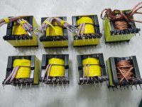
LLC Switching @ 200kHz @ full load with PC95, PQ5050 using minimal gain to reduce switching noise during light load.
Target Operating Voltage: +/- 50Vdc
1Mhz Operation.
Paralleled EPC2207
Bridged Mode
Balanced/Unbalanced input.
DC Offset protection with MosFETs & Optocoupler as switch
Protection: OTP, OCP
All connectors are PCB Mount.
Common Chokes are used in all rails.
Cant wait to have this powered up!
And I name it as TOP DOG. 😀😀😀
I am working on a new Class D with Ganfet. Heres what I am intending to have it in the build:
LLC Switching @ 200kHz @ full load with PC95, PQ5050 using minimal gain to reduce switching noise during light load.
Target Operating Voltage: +/- 50Vdc
1Mhz Operation.
Paralleled EPC2207
Bridged Mode
Balanced/Unbalanced input.
DC Offset protection with MosFETs & Optocoupler as switch
Protection: OTP, OCP
All connectors are PCB Mount.
Common Chokes are used in all rails.
Cant wait to have this powered up!
And I name it as TOP DOG. 😀😀😀
Attachments
Last edited:
Thanks! Too bad that I dont have experience with planar transformer before.
But few things come into my brain that if i am going to use one are:
1. When using planar transformer, i can only use very minimal number of turns for primary/ secondary winding due to its low profile physically, which means I need to shift the frequency all the way up to 500~1Mhz or even higher. If that's the case i need to use PC200 material for it.
2. But when the main output of slave winding is like only 2T to get 50Vdc, it will be hard for me to derive auxiliary 10~15Vdc from it, because 1T will be getting 25Vdc, or more when we pulling a lot current from the main 50Vdc.
😱😱
Hi!
Good job)))
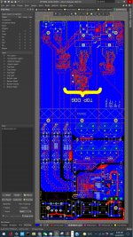
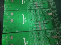
You use 4 layers PCB?
at 200 kHz I would use a planar transformer.
You can see it isn't 4 layer from the picture...
I am working on a new Class D with Ganfet. Heres what I am intending to have it in the build:
LLC Switching @ 200kHz @ full load with PC95, PQ5050 using minimal gain to reduce switching noise during light load.
Target Operating Voltage: +/- 50Vdc
1Mhz Operation.
Paralleled EPC2207
Bridged Mode
Balanced/Unbalanced input.
DC Offset protection with MosFETs & Optocoupler as switch
Protection: OTP, OCP
All connectors are PCB Mount.
Common Chokes are used in all rails.
Cant wait to have this powered up!
And I name it as TOP DOG. 😀😀😀
+/- 50Vdc using a PQ5050 seems like overkill, here the cost could have been shifted into the 4-layer and a PQ32/30 used instead.
I have few thousand of the PQ5050 ferrite and bobbin in store. So this size will be more preferable. 😱
They are actually not very expensive, just around USD5 for the ferrite and bobbin alone. Litz wire & labor come as free on my own hand. 😀
They are actually not very expensive, just around USD5 for the ferrite and bobbin alone. Litz wire & labor come as free on my own hand. 😀
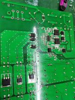
Impressive project. Whats your pri-to-sec minimum distance on the PCB? Maybe the pic is misleading, but it look like 2-3mm. Assuming 230Vac mains I think 6mm is recommended minimum.
Kind regards TroelsM
Kind regards TroelsM
I am keeping only 3mm for that, thanks for pointing out my mistake! 😱 I have never thought of it. Million thanks 
Keep in mind that transformer also must be constructed with correct clearance and creepage distancing.
Let me know if you want links for construction-tips.
Kind regards Troelsm
Let me know if you want links for construction-tips.
Kind regards Troelsm
Sure, i would like to take a read on these compliances to understand if I have did any mistake on the winding or not.
I have handmade few hundreds to thousands switching transformer, so far they "work fine" on the circuits. But I would like to take a look if I had comply to the design rules or not.
Appreciate it very much!!! <3
I have handmade few hundreds to thousands switching transformer, so far they "work fine" on the circuits. But I would like to take a look if I had comply to the design rules or not.
Appreciate it very much!!! <3
Attachments
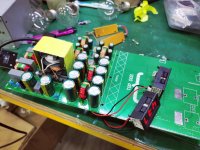
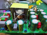
Just got the PCB! Hooked up the LLC, it works like charm.
Running at 240Vac, 15T on primary, 4T-0-4T on secondary for 40V+ 40V- 😀😀
Running at 240Vac, 15T on primary, 4T-0-4T on secondary for 40V+ 40V- 😀😀
Attachments
-
 205351662_1175318359647448_8095084070751225373_n.jpg112.9 KB · Views: 116
 -
 204018551_517459639467891_2361461298551313643_n.jpg73.3 KB · Views: 105
 -
 204595159_562937798064490_4413093931871953422_n.jpg130.9 KB · Views: 110
 -
 211737502_236587854965845_467331928912235546_n.jpg132.3 KB · Views: 207
 -
 204646467_996774941069479_719137134806346062_n.jpg130.3 KB · Views: 223
 -
 204409133_1235552493630831_9070731478237719800_n.jpg107 KB · Views: 219
 -
 208230545_514012996479845_8192769367539176692_n.jpg97.7 KB · Views: 219
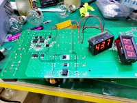
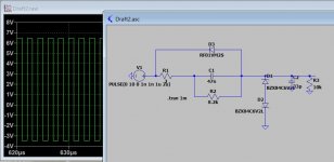
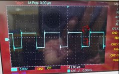
I am having some problem on the GAN gate drive. Which my intentional driving voltage is +6V, -3V, like what i shown in the picture. And hope some Gan players here can show some guide here.
1. The physical measured gate voltage is at +3V, -7V when it is running. Which is barely enough to turn on the GAN i think, thats why it ran hot.
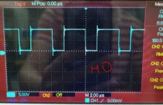
2. The HO output is perfectly fine at 10V referenced at 0V. And the high side driver is supplied regulated at 10V.
Heres my attempts:
i. I have tried to change the C1 from 1nF to 10uF. The larger the better, but just slightly better.
ii. Adjust the output frequencies from 200khz to 1mhz.
iii. Play around the zener diodes, and even if i removed them, i still getting +3V, -7V.
iv, Remove C2, R3. But still same. 😕😕😕
I have no clue on why the positive side is so low but the negative side is more.
*i am using infineon IGT60R070D1. 😕😕😕
1. The physical measured gate voltage is at +3V, -7V when it is running. Which is barely enough to turn on the GAN i think, thats why it ran hot.
2. The HO output is perfectly fine at 10V referenced at 0V. And the high side driver is supplied regulated at 10V.
Heres my attempts:
i. I have tried to change the C1 from 1nF to 10uF. The larger the better, but just slightly better.
ii. Adjust the output frequencies from 200khz to 1mhz.
iii. Play around the zener diodes, and even if i removed them, i still getting +3V, -7V.
iv, Remove C2, R3. But still same. 😕😕😕
I have no clue on why the positive side is so low but the negative side is more.
*i am using infineon IGT60R070D1. 😕😕😕
- Home
- Amplifiers
- Class D
- My built on Dual Feedback(Pre&Post) with GanFET