Overview from world's best historical and currently available electr/audio Magazines

Overview from world's best historical and currently available electr./audio Magazines

This could be an interresting collection of all magazines, not only english, French, German and Japan editions - we have more than 200 countries:
http://thumbs.dreamstime.com/thumb_367/1235114020ss78pr.jpg

I will start with a very small amount of editions and hope of much more, especially from the east European countries, but also far east countries, Brazil and the spain language countries (in the meantime relativ small losses by translate about "Fine-Reader/Google"):

Please note: no clean comparable test magazine for HiFi/audio like stereophile or the new "l' audiophile" here included - about this magazine listings go to
Audio Magazines


1) Electronics World
Electronics World - Electronics World
File:Electronics World Sep 1959.jpg - Wikipedia, the free encyclopedia
http://www.marklev.com/JC3/JC3-from-Electronics-World.jpg
Amplifier Articles in Electronics World & Elektor

2) Ремонт электронной техники (Repair of electronic components, Russian language - in this country all devices will be repair, even cheapest stuff like cell phones, dish receivers, cheap MP3 players and all the other electronic stuff)
http://www.radio-portal.ru/book/%C6...%ED%EE%E9%20%F2%E5%F5%ED%E8%EA%E8/2000_06.pdf
Æóðíàëû "Ðåìîíò ýëåêòðîííîé òåõíèêè"
http://www.shema.ru/0_s/mwo/SANYO/EMG_430.pdf
http://www.all-library.ru/zhurnaly/texnicheskie/1753-remont-i-servis-11-2009.html

3) 'l Audiophile (French)
http://6bm8.lab.free.fr/Documentations/Revues/Audiophile/index-1977-1988.html (index-1977-1988)
https://web.archive.org/web/20090218161354/http://www.audiophile.lu/index_fr.php
currently other magazine than from old days. Old magazines available on CD:
https://web.archive.org/web/20100518094713/http://nicolas.davidenko.perso.sfr.fr/revue/revues2.htm
https://web.archive.org/web/20100130100553/http://nicolas.davidenko.perso.sfr.fr/index.html
https://web.archive.org/web/2023120...LY/pXnJajbGgI4/s400/audiophile-couv-light.jpg
https://web.archive.org/web/20090205150033/http://www.audiotechno.fr/html/realisations.htm

4) "無線と実験" (MJ magazine, Japan)
all informations there:
http://www.diyaudio.com/forums/soli...sen-jikken-yearly-index-1924-2009-wanted.html

5) Elektor/Elektuur (German, Englisch, Dutch)
ELEKTOR.nl | Elektronica: Embedded Microcontrollers Audio Digitaal Analoog Testen Meten
http://miketimmer.nl/wp-content/uploads/Elektuur.jpg
Elektor Artikelsuche
paX: Audioverstärker mit Fehlerkorrektur - ELEKTOR.de | Elektronik: Analog Digital Embedded Mikrocontroller Audio Messtechnik
paX power amplifier
http://www.diyaudio.com/forums/solid-state/165165-edwin-20-watt-elektor-1970-may.html

6) ELRAD (German, no longer available, no successor magazine)
http://shackman-electrostatic-loudspeakers.reromanus.net/elrad-titel.JPG
Elrad (magazine) - Wikipedia, the free encyclopedia
HMG - Presse-Informationen - Heise Zeitschriften Verlag - 20.12.2005
heise online - ELRAD auf DVD
Shackman DIY Electrostatic ESL/ELS Loudspeakers and tweeters. Tube/valve amplifiers Röhrenverstärker. Elektrostatische Lautsprecher Elektrostaten-Selbstbau Audio engineering Literature

7) "Chip" and "populäre Elektronik" (German, no longer available, no successor magazine)
http://www.gw-home.de/images/elektronik.jpg
http://resources.emartin.net/blog/pic/Populaere-Elektronik-1982-10-sm.jpg
Populäre Elektronik ? Wikipedia
1978-1983 Vogel-Verlag (emartinnet)

8) TAA ("The Audio Amateur") and "Speaker Builder"
http://www.arcdb.ws/ST70C3/AudioAmateur_4_1977.jpg
http://www.carveraudio.com/sb[1].jpg
http://www.alkeng.com/bruce2.jpg
AUDIO AMATEUR BACK ISSUES
http://www.passdiy.com/pdf/citation.pdf
A75 Part 1
https://www.wilmslow-audio.co.uk/catalog/index.php?cPath=39
Ribbon Tech
The Maverick 2's

9) Funkschau (German, in the early days similar to Japan's MJ magazine)
http://www.guenthoer.de/doku/funkschau-2284titel.jpg
http://www.suertenich.com/html/radios/Concert_Boy_Funkschau.jpg
http://www.suertenich.com/html/radios/grundig_58.html
http://www.addx.de/textarchiv/archiv-funkschau.php
http://de.wikipedia.org/wiki/Funkschau
http://www.radiomuseum.org/forum/funkschau_1944_jahresuebersicht.html
http://www.jogis-roehrenbude.de/Russian/Funkschau-Ru-Roe.pdf
http://www.earlytelevision.org/images/FunkschauNov1936_1.jpg
http://www.earlytelevision.org/images/

Symasym 5.3 completed boards for sale

One pair for stereo amp completed boards for sale with original Onsemi transistors. Ad your own input capacitor and Psu and you have verry good sounding amplifier. Build with good parts. Price is 50 euro for bouth boards and caa. 14, 90euro shipping inside EU.Payment with paypal with option for friends and family.

Attachments

  • IMG_20210725_135302.jpg
    IMG_20210725_135302.jpg
    663.7 KB · Views: 343
  • IMG_20210725_135307.jpg
    IMG_20210725_135307.jpg
    501.5 KB · Views: 331
  • IMG_20210725_135312.jpg
    IMG_20210725_135312.jpg
    669.7 KB · Views: 339
  • IMG_20210725_135324.jpg
    IMG_20210725_135324.jpg
    603 KB · Views: 311

6n23p SWGP matched pair-NOS tubes

For sale Nos matched pair of verry good sounding tubes buyed by Tubesandmore from Netherlands. 6n23p typ with rocket logo from 1977 and silver shild, single wire!! I pay about two years back 75 euro for a piece so 150 for pair plus shipping. I dont have original boxes anymore, I cant find this, but I will pack the tubes verry well. I buy this tubes for my tjoeb cd player but on the end I have use in there Siemens e288cc, so this tubes have around maybe 10 working hours and not more. So condition is like new. I would sell this for 100 eu plus shipping inside eu or best offer. This are one of the best sounding tubes and you can use this in place for ecc88, e88cc, 6dj8.......!Shipping inside EU 7,90 euro.

Attachments

  • IMG_20210522_182619.jpg
    IMG_20210522_182619.jpg
    241.4 KB · Views: 423
  • IMG_20210522_182641.jpg
    IMG_20210522_182641.jpg
    259 KB · Views: 403
  • IMG_20210522_182658.jpg
    IMG_20210522_182658.jpg
    236.2 KB · Views: 413

Arrow

Anyone else had any issues with Arrow?

I was having quite good luck with them for a while but...

I ordered 16 caps on June 7th. They figured they would ship on the 11th and I'd have them by the 15th.

They still haven't shipped them.

Four times I've contacted support through chat. Four times I got the same "I'll make sure the warehouse expedites your order"

The last time I asked to cancel it since it hadn't shipped. The chat person said they couldn't do that.

I then tried to call them on the phone. The first time the automated system said it couldn't take my call and to call later.

The second time I got to hold for someone for someone for 25 minutes only to have it ring through to a silent line which I hung up on 5 minutes later after saying "Hello? Is someone there?" a few times.

I've now opened a dispute with Paypal. Let's see if that get's there attention.

Anyone else have any stories to share about bad purchase experiences? I've never had this much of a hassle with any other place. That includes sellers on eBay and Aliexpress.

Koda

Great AB Amp

Hi,
I have only experience with Class A Amps (Pass XA25, Aleph J, Bba-3…) to drive my Magnepan 1.7i.
Best match is the XA25.

In summer time, the heat development is heavy in my listening room.
I am interested to build a high class ab amp and hope I will get some input here.
First candidates I found:
- Pass AB100
- SymAsym

Any comment or tips?

Thanks 😉

Daniel

Hypex amp and psu modules

Years ago, I bought a huge lot of used Hypex modules. When I bought it I was told that most are working but there might be some that are not working. I have randomly picked some psu and amp modules from the lot in my own projects during the years and only found one bad amp module and one bad psu module. Here is what I have left. I haven't tested them and don't have the energy or time to test them so for that reason I'm selling them as unknown condition.

2pcs SMPS1200A180 V7. These are missing the heatsink, otherwise no visible defects

1pc SMPS1200A700 V3. No visible defects

2pcs SMPS400A180 V9. No visible defects, except the plastic covering over the electrolytics is worn

10pcs UcD180LP OEM V8. No visible defects

I preferably sell all of them as a lot, how about 150€ for the lot + shipping. Or make me an offer of what you want. Can be shipped anywhere, just ask for shipping quote.

Detailed photos can be found in below link:
Hypex - Google Drive

Attachments

  • IMG_20210809_085457 (1).jpg
    IMG_20210809_085457 (1).jpg
    985 KB · Views: 328

Driver measurement: mic position?

I'm in the process of designing a modest two-way speaker. Up until now I've only made XO's by using the verdor-provided FRD and ZMA files (or I traced graphs if needed). This time I want to measure the drivers first ("gated"), and design the XO based on my own measurements. I've been reading up on how to do this from various sources, like posts on this forum and the REW help file. I have two questions left at this point.

  1. Should measurements for both drivers be performed with the mic on the v-axis of the tweeter, or on the vertical axis' of each individual driver?
  2. Can I just use the vendor-provided ZMA file? I have a measurement mic but no DATS or similar.

Problems Sure amplifiers

I have two Sure amplifiers that have problems.

AA-AB013V120: This one has never done it. I have used different power supplies. The Hmute light is on indicating there is a problem.

AA-AB32971: This one I bought recently. It sounded very good with this power supply Gratis Verzending 240 w 24 v 10a Enkele Output schakelende suppy in Gratis Verzending 240 w 24 v 10a Enkele Output schakelende suppy van Stroomvoorziening op AliExpress.com | Alibaba Groep

Unfortunately one of the channels suddenly failed and a red light on the board is indicating an error occured.

In both cases the manual gives no information what to do. Any suggestions from this forum?

6P6P 10W + 10W from China

Hello there,
I am currently working in China and I am thinking to visit the factory producing this amp US line 6P6P 10W + 10W super linear push pull tube amplifier, CLC filter, S / N up to 108db|Transformers| - AliExpress
It seems they are taking care of finding right components, but I am not an engineer so my knowledge is always limited, does people here have an opinion on this ?
O1CN01NrugOc2F5GxNJKVP2_!!50308828.jpg


O1CN0113WTWL2F5GxPeSUCn_!!50308828.jpg


They also have one similar with a closed box design.
I find it interesting these small chinese companies making vintage circuitry design come alive.

Simple Low Distortion JFET Buffer

Attached is a schematic and simulation results for a simple cascoded "Fetwhite" buffer. The simulation results were surprisingly good, so I did a hack job on one of my buffer modules to try it out in my test preamp. Audible results are excellent. The unit gain buffer is also a good gain match for my overall system.
I will need to wait until I'm back at work next year before I can really do any serious testing on the new circuit, as all the good gear is there. It will be interesting to see if the test results for THD are anywhere near as good as the simulation.

I plan to try out some simulations to check the difference between using a simple cascoded buffer and the White circuit. Last time I loooked, the White circuit had lower distortion, but the simple buffer would allow me to try a cascoded bipolar current sink instead of the JFET current sink current used here.

Attachments

  • jfet_buf_sch.gif
    jfet_buf_sch.gif
    41.1 KB · Views: 5,730

Yamaha A1 integrated - preamp's quality?

I have the opportunity to purchase a Yamaha A1 integrated amp at a low price and am happy to service it myself.
I intend to use only it’s pre section teamed up with a my recapped Yamaha P2200.

Please could anyone comment on the quality of the A1’s pre amp?
I hear that the phono section is very very good, and I only need a couple of inputs.

Would the audio quality be as good as a Yamaha C4, or the pre in a CA1000, CR-1020 ?

Autoformer

So.....

i have this autoformer from Dave Slagle, the ELMA stereo version

Gonna use this as a volume control in an enclosure with 1 out, 3 inputs
maybe later add an XLR balanced line in/out

-i want to use a selector or toggle switch
the selector needs to be 2 pole,4 pole? where can i find a 3 way toggle switch?

-does anybody have a wiring diagram, i know this shouldn't be difficult but this design is quite new for me 🙂 so just wana make sure!

Cheers all! Filip

Attachments

  • 124913824_382d56a3725b4b80aa9cb3ee5cae519f.jpg
    124913824_382d56a3725b4b80aa9cb3ee5cae519f.jpg
    322.4 KB · Views: 121
  • 124925520_8bc97bfc31d74a32ae57131c4240281a.jpg
    124925520_8bc97bfc31d74a32ae57131c4240281a.jpg
    317.4 KB · Views: 123

Bluetooth audio receiver - High frequency noise/hum

Hello!

I am currently building a Bluetooth portable speaker. Everything about the build was okay but there is one thing bothers me a lot, the Bluetooth receiver generates noise no matter what power source I connected it to.
The hum is in high frequency and the frequency goes up and down. Somehow the noise is a bit better when I turn the volume knob(b100k) all the way up, and somehow, the hum will eventually gone after powering up the speaker a while, leaving an acceptable white noise at the background like an old FM receiver. The noise also decreases a bit when it is streaming songs through Bluetooth, when the music stops, few seconds later the Bluetooth receiver sort of switch to idle mode(? and the high frequency noise is back again.

I did tons of searching on the internet to find the solution, and everyone solved the problem by using a dc-dc isolator, I did the same and it didn't work for me.

Because I can't do anything with it, I had to ask here. At this point, I wish I know the circuit design of those speakers from big companies. How JBL managed to get a very clean sound out of a Bluetooth module??

Anyway, here is the my circuit diagram.
An externally hosted image should be here but it was not working when we last tested it.


sorry for the bad schematic, I am still new to this area.

Advice on speaker purchase...?

I know this is diyaudio but i hoping i can get some help with a buying advice.

My company has a big meeting room (hard floors, office type of ceiling tiles, lots of glass windows (top to bottom) and about half with interior walls.

In one end we have a projector with a decent size screen where we hold company meetings (with zoom for remote employees). we use round 6" speakers (four) flush mounted in the ceiling tile for sound, both amplifying the voice of the speakers as well as to hear people on zoom.

The sound is absolutely dreadful. We often do happy hour after company events and i put on playlists from spotify but its terrible.

I'd like to get a decent set of speakers (on floor or in ceiling) that can be used for both voice (PA) and music for happy hour. It does not need to be super loud (We're not dancing) but decently volume is needed.

Any idea what to buy? I was tempted to rush over to best buy and get some klipsch monkey coffins for a few hundred bucks but decided i should first check with you all for ideas?

I have the amp, a regular onkyo amp that seems decent and i'm donating my personal hometheather powered subwoofer to them (i've upgraded).

So any ideas on speakers you think are good for this usage? I can go up to lets say $1,000 or $1,500 but we are scrappy -cheaper is better...

thanks a bunch!

JBL GTQ360

This amp is sort of similar to the GTS300

This amp is drawing .5A with just + and - connected. When I attach REM, the amp powers up and idles at 2A. Channels 1&2 work, but channels 3&4 do not.

In troubleshooting the PS side, I pulled the PS driver board which also removes the TL494 from the amp. Still drawing .5A.

Anyone familiar with these?

FS: speaker drivers

I have some speaker divers for sale
Dynaudio midbasses 2 pc (in guess they came in volvo doors and are 8") working good condition
Focal 6,5" k2 midbass drivers 2 pc not good contition
Fountek FR59EXE 2pc tried in car use
Dayton audio RST28 tried my home speakerd good contition 2pc
Seas 27tbfc/g good condition 2pc
Seas h 87 one does not work 2pc

All drives 125 euros + shipping.

Google Drive: Sign-in

Google Drive: Sign-in

Google Drive: Sign-in

Google Drive: Sign-in

Google Drive: Sign-in

United SiC UJ3N065080K3S, Is there any triode behavior?

I am opening a thread for the UJ3N065080K3S SiC JFET. Is there an operation area that has triode-like behavior?

This is a thread for curve tracer geeks.

I have attached the results of a curve tracer session of mine on this JFET.

In my experience, devices that have triode-like behavior, this behavior is at high-ish voltage and low-ish current. These same devices have pentode-ish behavior at high-ish current and low-ish voltage. I will post that behavior in the next post.

Attachments

  • UnitedSIC.jpg
    UnitedSIC.jpg
    94.4 KB · Views: 873

DIY Novar Socket

I found a source for PC solder pins that work with Novar tubes so I designed a circuit board for a Novar damper diode power supply. It can be used in a hybrid bridge configuration or with a center-tapped xfmr by just leaving out the diodes. Also, the heaters can be powered by a separate or common supply by installing a couple of jumpers.

These are not for sale, but to get an idea of the cost, the boards were $2.00 each including shipping. The pins are $0.66 each. I only populated the active pins, 5 pins per tube. The PC terminal blocks are about $8.00. So the cost comes out to about $17.00 for the whole thing.

This may be overkill but I think it's a neat idea. Makes the terminations easy.

Scott

Attachments

  • 20140601_125140.jpg
    20140601_125140.jpg
    210.5 KB · Views: 494
  • 20140601_125256.jpg
    20140601_125256.jpg
    308.7 KB · Views: 461

Kenwood L08m relay problem

I am working on a pair on L08m Kenwood Mono blocks- one works fine, the other has a NFB (RL1) relay that keeps clicking. The rate of clicking is associated with the offset adjustment.

The problem is I do not have 24v on the coil, and when I trace this back it comes from one side of R112 in the attached diagram. The other side or R112 is attached to the Collector of Q47, which in the bad amp is 0v, whereas it is 64v on the good amp. So I surmise it is not being turned on. Q46 and Q47 drive this relay.

As I trace this back-Q39 on the good amp has 8v on the collector, where as the bad amp has about 3v (fluctuating).

I have repalced all the caps, tested out of circuit all the transistors and tested in circuit all the diodes-and replaced a couple-all the resistors have been tested in or out of circuit depending on their measurement, again all test good.

I have checked (and checked again) all cap values and polarities, but I am at a loss to understand why the circuit is misbehaving. The voltage at the junction of C29 and D33 is 12v on both good and bad, and the B+ measures at 65v at the emitter of Q46 and Q45, and both there bases are at 64v (or so).

On the good one the collector of Q46 is 65v (as is the emitter of Q47), where as it is 55v on the bad one.

So I think something is not being turned on

I have attached the overall circuit, page on the relay operation and circuit oif that section with voltages. The additional complication is Q40 and Q41 which are not shown on the circuit and are mounted on the PCB and listed in the parts list.

I will try and trace out where they connect. Q40 shares a common collector with Q39, other than that their voltages are the same on the good and bad units

any thoughts as to where I should be looking?

Attachments

For Sale: Peerless by Tymphany NE265W-04 10" Paper Cone NE Woofer 4 Ohm

For Sale: Peerless by Tymphany NE265W-04 10" Paper Cone NE Woofer 4 Ohm

$100.00 Shipped CONSUS - USPS Tracked

I purchased this driver from another member in 2019 thinking I would use it in a three way build but went another direction. I did recently put it in a 1 cubic/ft sealed enclosure for testing and it worked flawlessly.

Peerless by Tymphany NE265W-04 10" Paper Cone NE Woofer 4 Ohm

Will be shipped in original box. Thanks for looking.

Attachments

  • IMAG1091.jpg
    IMAG1091.jpg
    871.8 KB · Views: 323
  • IMAG1090.jpg
    IMAG1090.jpg
    812.3 KB · Views: 316
  • IMAG1089.jpg
    IMAG1089.jpg
    337.4 KB · Views: 300

For Sale: Capacitors, Inductors, Resistors - Jantzen, Dayton, Mills

For sale are a mixed bag of Capacitors, Inductors, and Resistors.

$60.00 Shipped CONSUS - USPS Priority Tracking

I am selling all together for way below what it would cost to purchase individually.

Never soldered only tested. Let me know if you have any questions and thanks for looking!

Inductors
Jantzen Copper Foil 1.20mH 14 AWG
Jantzen Air Core 2.5mH 18AWG
Jantzen Air Core 2.2mH 18AWG
Jantzen Air Core 0.8mH 20 AWG
Jantzen Air Core 0.55mH 20 AWG
.10mH 20AWG

Capacitors
Jantzen Audio Silver Z-cap 3.3uF
Jantzen Audio Superior Z-cap 3.3uF
Janzen Standard Z-Cap 6.8uF
Jantzen Cross Cap 12.00uF
Solen 11uF
Dayton MPT 90uF
Dayton MPT 4.7uF
Dayton MPT 2.7uF

Resistors
Mills 8 ohm
Mills 16 ohm
Mills 6 ohm
Jantzen 4 ohm
Jantzen 2ohm
Jantzen 2ohm
Jantzen 22 ohm

Attachments

  • IMAG1086.jpg
    IMAG1086.jpg
    1 MB · Views: 566
  • IMAG1087.jpg
    IMAG1087.jpg
    493.6 KB · Views: 557
  • IMAG1088.jpg
    IMAG1088.jpg
    441.4 KB · Views: 506

Buff IIISE DSD256 and higher crackling

I have a vexing issue with DSD and was wondering if there was a simple, obvious solution I was missing.
I'm playing native DSD recordings from my Dell laptop with Core i7 processor to my Buffalo IIISE DAC through a Sonore Audiobyte USB to I2S board and get great sound with PCM at all rates, and with DSD64 and DSD128. When I get to DSD256, though, playback has a low-level crackling sound mixed in with the playback. I hear the crackling whether I play the files using Foobar (with a multitude of different settings) or HQ player (trying every filter and modulator setting on HQplayer).
I have the Buffalo IIR filter set at the default (recommended for PCM). I'm thinking if this was an issue with the Buffalo's IIR filter, for example, it would also happen with the DSD64 and DSD128, right? Or could the higher sample rate of DSD265 cause issues with the DAC that don't appear at the lower rates? The dip switches are not very accessible in my DAC so I'd like to known if I'm barking up the wrong tree before I tear into the unit.

Any help is greatly appreciated!

Automatic Extraction of Minimum-Phase Response

Dear All,

Anybody who ever measured a loudspeaker driver using MLS or ESS measurement systems faced a problem with placement of FFT window. In order to obtain true minimum-phase phase response, the FFT window must be located where it should be.

I have produced two papers describing the method of dealing with this issue.
In the first paper, I introduce Inverse Hilbert-Bode Transform and it’s application.

https://www.bodziosoftware.com.au/IHBT_White_Paper.pdf

The second paper describes an automated method for extracting minimum-phase phase response and more.

https://www.bodziosoftware.com.au/Automated_IHBT.pdf

If you have any questions, please contact me on
bohdan@bodziosoftware.com.au


Best Regards,
Bohdan

LM3886 getting hot and 0v at the output

Hi,


This is possibly similar to LM3886 - getting hot - low volume


I've soldered up my LM3886 board and getting a hot chip (using a bad heatsink, if I use pliers to press it against a big heatsink then doesnt get hot).


The main issue I have is that it's apparently outputting 0v at the output with no load connected, and PC line output connected as input with no input attenuation via a volume potentiometer.


I had previously built a veroboard version (minus the zener mute function, minus the thiele and zobel networks) and that used the same bad heatsink and worked and had no heat issues.


This is a different chip - when I get time, I will swap the chips to see if I have a faulty one.


I'm using a pcb this time for the new amp, components are more compact compared to veroboard.


Rgb1 on the schematic is just a bit of hookup wire that has not been soldered - intent to use 1ohm 1w resistor. This might be causing issues, although continuity seems fine on those points, it might be introducing noise.


Anyone able to point me to the right direction please?

Attachments

  • Screenshot_20210414_014935.png
    Screenshot_20210414_014935.png
    26.6 KB · Views: 590
  • Screenshot_20210414_015102.png
    Screenshot_20210414_015102.png
    63.4 KB · Views: 580
  • Screenshot_20210414_015113.png
    Screenshot_20210414_015113.png
    63.2 KB · Views: 552
  • Screenshot_20210414_020320.jpg
    Screenshot_20210414_020320.jpg
    87.5 KB · Views: 567
  • Screenshot_20210414_020334.jpg
    Screenshot_20210414_020334.jpg
    120.1 KB · Views: 519
  • Screenshot_20210414_020347.jpg
    Screenshot_20210414_020347.jpg
    101.5 KB · Views: 257
  • Screenshot_20210414_020401.jpg
    Screenshot_20210414_020401.jpg
    80.6 KB · Views: 237

Arduino with 3 Display boards - YM2004A, 2004A V1.2 U3

1 Arduino board with Buffalo Shield and 3 Display circuit boards.

I've never used these and I believe they were attached to a Arduino controller for a Twisted Pear DAC layout. I picked them up as used parts with other Twisted Pear items (see other offers here).

Display 1: YM2004A and has a small daughter card on it (I2C LCD extra...)
Display 2: 2004A V1.2 U3 also with small daughter card (TWILCD)
Display 3: NewHaven NHD-0420dzw-aq5 with large daughter card (CE-Designs CE644 V1.3) and some cabling

Arduino board model UNO r3 with Buffalo Shield V1.0 and Apple remote.

I don't have a way to test these, if not functional we will work out a refund but I believe the Newhaven and the Arduino were still fully functional when pulled.

$85 includes shipping to contiguous USA Only.

Payment via Paypal friends/family required before shipping.

Attachments

  • 22.jpg
    22.jpg
    650.1 KB · Views: 131
  • 32.jpg
    32.jpg
    711.7 KB · Views: 141

Twisted Pear Legato, LCBPS power supply and additional parts

Twisted Pear:
Legato analog board
LCBPS power supply
Sidecar
2x master clock cards for the 9018 board
2x pinned to i2s adapters
volume board with knob and LED's.
And for fun Texas Instruments +/- 15v regulator boards (NON twisted pear).

$100 includes shipping to contiguous USA Only.

Payment via Paypal friends/family required before shipping.

Attachments

  • 11.jpg
    11.jpg
    683.4 KB · Views: 149

Rega Planar 3/2 - Significant modifications

Hi, I originally posted this in another forum, but felt members here may benefit from this also, so I am re-posting some key elements in the processes I used.

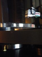
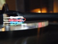
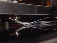
I just rewired my RB300 tonearm, with Isokinetik silver plated wire (Cardas cartridge clips with Mundorf supreme silver lead free solder) : straight loom to the phono preamp..., and finished making a custom 3kg disc to mount the motor from the Rega Planar 3 on. I also dampened the tonearm with 7 expandable earplugs, and put 2 very thin slithers of earplug foam inbetween the spring coils in the weight adjustment part of the tonearm (they ring like a bell), while it was set at 3.5g (maximum-opens the spring up totally) and then set the weight via jewellers scales - leaving the setting at 3.5g.

I have NEVER heard a Rega sound soooooooooOOOOOOO GOOOOOD...!!!

Extra wide soundstage, depth, transparancy, black-silent background, detail, with a laid back clarity...yet so much PUNCH and tight bass....

...and its still in the initial hours of being 'burnt-in'....I cant tear myself away from it.....I also have a ruby bearing in it, and acrylic platter. In the lead base, which I made from a jar stainless lid, I drilled a hole, got a paper-mate biro pen, and took the spring out, cut it in half, and put it in the hole, and used the steel bearing I replaced with the ruby one, for the platter, and used it for a 'thrust bearing' as part of the lead base.....

...man, what a rewarding effort...., some tracks evoked pure emotion....WoW

... I still need to finalise a few minor points...ie: ext-cable clamp, 3 point mini-feet on base etc...,

... that is an 'ancient' Shure M75EJ Type II on there with a near-new Swiss Huco Hyper-elliptical .2 x .7 stylus...The Nagoaka MP-200 is looking like a good cartridge/stylus....for future consideration hmmm

Attachments

  • Rega sideprofile.jpg
    Rega sideprofile.jpg
    612 KB · Views: 2,185
  • Rega wiring.jpg
    Rega wiring.jpg
    612.4 KB · Views: 2,022
  • Rega extwire.jpg
    Rega extwire.jpg
    663.3 KB · Views: 1,997
  • Rega base.jpg
    Rega base.jpg
    600.8 KB · Views: 2,044

Tannoy TS10 repair

Just repaired Tannoy TS10sub.
Green light was on but no output.
Got schematics from here.
I dont have a scope so i
used a cell phone frequency app generator to line in L/R.
Traced with input to mini speaker which i saw on Billm Audio.
(Youtube)
Signal got to audio amp board then died.
I checked many components all ok.
Caps had no signs of releasing smoke buy i ended up recapping
5 electrolytic and 3 BP caps anyway. I figure one of the BP's in line were dead.
Tested all caps off board which showed all out of spec readings.
RT1 was suspicious reading 121ohm but I left in and thought I could
jump to test if recap didn't work.
Works fine now.
As EEV Blog David Jones (Youtube) would say.
Winner winner chicken diner!

Roland AC90 Amp sound clipping on off

Hi everyone,

I am working on a Roland AC90 Guitar Amp that is playing ok on very low volume but when volume is increased slightly it starts to clip on and off constantly. Like turning volume up and down very fast. I tried to attached a video of its performance but says file invalid. I’ll try and get a different method.

I disconnected the main drivers and tested all the outputs individually through another system Mono out, phones out and left and right out and all work absolutely fine, which makes me think the problem is on the AC90 Amp board. I had a look at the components on the board and all seems ok visually.


Would anyone have come across this fault before with this amp?

Any thoughts much appreciated.

Regards

Paul

Attachments

  • 17CA97DA-DF21-4243-9382-9C6A60AC32ED.png
    17CA97DA-DF21-4243-9382-9C6A60AC32ED.png
    286.7 KB · Views: 226
  • 23E4E419-F24F-4137-A2DD-53CC799CBD92.jpg
    23E4E419-F24F-4137-A2DD-53CC799CBD92.jpg
    852.9 KB · Views: 222
  • 3BD98F65-D82B-4682-9705-A95F4ACFF8BC.jpg
    3BD98F65-D82B-4682-9705-A95F4ACFF8BC.jpg
    859.8 KB · Views: 207

0 Bias Class B, Possible?

Based on the definition, class B amplifier should have 0 bias current. However, I have not seen any hifi amplifier with a pure class B design (with 0mA bias), even labeled with Class B. They all have some bias presented, such as 10mA.


Couple Question.
1. Is amp with 0 bias output stage possible? It is efficient, runs cool. Why nobody use it.
2. It seems to boil down to the distortion. We have solved the switching noise of class D, why nobody solve the switching noise of class B? Maybe somebody did, I just don't know.

Digidesign 888 | 24 interface DIY mod

I recently bought a Digidesign Mix system consisting of several DSP PCI cards and an 8in/8out interface called "888" . The system uses a PC/MAC for running Pro Tools TDM. The problem was that the interface is a bit outdated and the sound is not extremely pleasing. The sample rate and bit depth reaches 48KHz/24bit maximum. Taking into account that the newer Pro Tools HD system is really expensive, I bought the older MIX system with the perspective of modding the interface to unveil the hidden capabilities.

Before starting the mods, I searched the internet for relevant info and didn't find anything. After months of experimenting I found the best combination of opamps and caps regarding my personal taste: Quick opamps with robust lows and detailed highs.
Here is what I did:

-Replaced all AD711 with LME49710
-Replaced all LF353 with LME49720
-Replaced all N5542 with LM6372
-Replaced L7805 with L78S05 and replaced the heatsink as well
-Replaced all SSM parts with equivalent THAT.
-Replaced the switching PSU with a bigger one of greater ampere value (+15V, -15V, +5V) because the new opamps draw A LOT more current.
-Applied decoupling ceramic COG caps 10nF/50V to all opamps
-Replaced all SMT electrolytics (most of them are 10uF/50V) with Panasonic FK (smaller size and far better specs).
-Replaced the 220uf/35V caps around the L7805 regulator with Panasonic FM 1500uf/35V

The sound changed DRAMATICALLY. And after adding/replacing the caps, I had no thermal issues.

Objective Guide to Op-Amp Rolling - Part 1

Hi,

For my last blog article, I compared the performance of:
  • Texas Instruments LME49720
  • Texas Instruments OPA2134
  • Texas Instruments LM4562
  • Texas Instruments LM833
  • New Japan Radio NJM2742
  • Analog Devices LT1352
  • Texas Instruments NE5532
  • New Japan Radio NJM2732
  • Analog Device LT1169

See here:
Objective Guide to Op-Amp Rolling - Part 1

Regards;
Leo

Crossover on a ground plane

Hello

I was thinking of assembling my next xover on a single side copper plated PCB like this one. So everything connected to the ground is soldered through a little hole to the copper plated part, the remaining connections wired p2p on the other side, and the components affixed with cable binders/hot glue.

What would be the advantages or downsides? Has anyone experiences. I was also considering to get oriented grain steel foils, which would then be used to wall the inductors, and that would also be connected to the ground plane.

Room Gain for ported subwoofer

Hi guys ... Please see the attached image.
This is a Winisd simulation of a ported sub.
Black - without room Gain
Red - with room Gain starting from 28hz

Now the question is ...
1. Is the increase in SPL due to room Gain looks realistic ??
I mean how close is the Winisd estimation to the real world.

2. Room Gain works differently for sealed and ported subs ??

Attachments

  • IMG_20210805_220332.jpg
    IMG_20210805_220332.jpg
    145.2 KB · Views: 238

Sub amp proximity to main speakers?

Sub amp is Dayton Audio SA1000, 950W @ 4 ohm, 1/3rd duty cycle, class AB, Carver down-tracking PS, ca. 29#, in production since ca. 1995 with only minor series change: added HP main speaker filter, subsonic filter, switchable 20 Hz EQ, rest of the amp unchanged.

Two SA1000 power a 4 sub array, two subs per L/R side. SA1000 are in Dr. David Griesinger's phase quadrature tuning, the L and R sides separated by 90 degrees to further maximize the array's natural mode damping.

The two front subs also serve as main speaker stands; each side wall has a sub.

To minimize SA1000 output cable length I sited each SA1000 vertically only an inch from a cabinet housing a reverberant field accessory speaker driver, an Eminence coincident 10" with compression driver (separate xo.) Imaginary V-lines from the sweet spot pass through the center of the Eminence 10" directly behind the sub/stand/main speaker.

The SA1000's horizontal face plate and the baffle (22 degrees from horizontal) housing the Eminence 10" are both 16" above the floor.

Overall performance improved a lot, including the bass, vs. my prior SA1000 siting with longer output cables.

How would you define perceived risk (if any) Re. SA1000 proximity to main speakers or 10" sub drivers? The Q presumes no speaker driver, esp. the 10" sub, is on 90 degree axis with SA1000.

Hypex amp and psu modules / lot 2

This is a fully working set of Hypex modules. I used these to drive my LX521 speakers. This set makes 8x400W amplifier. All modules are directly from use.

The lot includes following modules:

4pcs SMPS400A400 V14
8pcs UcD400OEM V6
Some wiring + connectors, if needed
Aluminium parts and any other parts in the photos are not included

How about 300€ for the whole lot or make me an offer of quantities that you need.

Photos here: Hypex2 - Google Drive

Attachments

  • IMG_20210809_091906.jpg
    IMG_20210809_091906.jpg
    1.1 MB · Views: 235

Grounding arrangements for star ground

Lets not bring device-to-device ground loops into the picture, for now just assuming the amp byself with the following components on seperate boards, each with it's own ground.

Power Supply
Low current input stage
High Current output Stage
RCA input
Speaker output


So we have 5 grounds here, staring all 5 of these components to a common point results in 120 hz hum.

What arrangement of star grounding(s) would result in the least amount of hum? I have been playing around with different combinations for about a hour and a half now and I can't eliminate the hum.

Ultra low noise amp with JFET's - How to reduce the THD ??

Hey guys!

I'm trying on building some nice simple ultra low noise amp with noise values below the 1 nV/rtHz level. Read many papers and threads about that topic and built up several little amps with low noise JFET's like 2SK170, 2SK369 and IF3601. I use them in source mode going into a non-inverting Opamp LT1028 as second stage. My noise values and bandwith are good.. reached like 0,3 nV/rtHz and bandwith up to 1 MHz. So that's good, but what's not so good is the THD ! Often I got like 3-6 harmonics resulting in THD's of 0,5 to 3% so that's way too high for my application. I need some value below 0,1%.
Biassettings of the 2SK170 for example are like Uds = 8V , Ugs = -0,12V and Id = 6 mA. So those values should work out for good linearity in the input and output curves. But they don't :-( Mostly I get strong second harmonic.
I put up my basic schematic and a picture of those bad harmonics I get, hoping that anyone knows how to effectively reduce that THD!! Or is it not possible in a source-circuit to drop the THD below 0,1% ? Do I need some complementary stage or feedback to get better?

Supply voltage is +-12V not 5V and signalsource is like 10kHz with 10mVpeak.

Thanks for your answers,

Greetings
Tobi

Attachments

  • forumsbilder.jpg
    forumsbilder.jpg
    33.8 KB · Views: 1,774
  • Id_Abgleich.jpg
    Id_Abgleich.jpg
    27.1 KB · Views: 1,397

What JFET should i choose for a preamp?

Hi all.

I have build quite a bit with BJTs and opamps over the time, but I feel it's time to play with JFets, now that I'm in the planning phase of a preamp.
I struggle to understand noise figure on JFETs. My local supplier have the following:
2N5459: Noise figure: 3,0dB af 1KHz; Rg = 1mohm
BF245A: Noise figure: 1,5dB at 100 MHz; RG =1kohm
2SK246: No noise figure in datasheet
2SK117: Noise figure: 1dB at 1khz; Rg = 1 kohm

The 2N5459 is quite cheep, while the 2SK117 is expensive, so what is enough? I'll need normal line-in and a RIAA for MM.

AK4458VN and AK5554VN for sale

Hi,

I am offering the following AKM ADC/DAC for sale :

40 pieces of AK4458VN 32bit 768kHz 8ch DAC (39USD/piece)

40 pieces of AK5554VN 32bit 768kHz 4ch ADC (39USD/piece),

bought from Digikey in Aug-2020 for prototyping which never happened after AKM plant fire.
Components still in original sealed packing, not opened yet.
Only for sale as whole packing (either type).

Attachments

  • AK4458VN_1.jpg
    AK4458VN_1.jpg
    474.2 KB · Views: 90
  • AK5554VN_1.jpg
    AK5554VN_1.jpg
    417.7 KB · Views: 98

Kenwood L-07M info needed please

I have a pair but alas no circuit diagram, they are both working fine and show good 50k square waves stable on the scope and have equal low noise, but one is warm and the other is cool, so i need to do a bias adjustment, and also dc offset adjustment.

I've found 3 pots on the input/driver board, which I have no idea which ones what. One has to be for bias which i need to do, the other for DC offset which i also need to do and the third I have no idea what it does.
Does anyone have the info or a diagram on which does what. It's so dark and dingy down in there and cramped, I can't even see the emitter resistors so i can check the bias across them.

Your help will be grateful
Cheers George :xeye: :xeye:

KENWOOD L-07 CII preamp

It's my first thread here.

I have a Kenwood L-07 CII with a problem on the right input phono MC stage ( noisy with cracking... ).
But without diagram impossible to repair.
And also impossible to find service manual, schematic, information about, ...

Please I need your help !
Raymond

My preamp :
An externally hosted image should be here but it was not working when we last tested it.

buzzing input...

Dear builders
Uhm...
My preamp has an annoying buzz. it's not very loud (music overshadows it) but constantly there.
It is not being attenuated (level is constant).
I disappears when I unplug the only input, a USB-dac.
swapping the dac doesn't change, I use a halide DAC HD (usb-powered) or a furutech ADL gt-40, more a preamp than just a dac)

Am I describing a ground-loop?

Many thanks!

Rookie question about thermal pastes

Rookie question about thermal pastes / Rectifier Q

Hi all,

I've had to unbolt this heatsink to move my PCB so I can replace the speaker relay on the board. About to put it back together and thought maybe this paste is insulating the rectifier from the chassis ?

I've looked up the datasheet and it states 'Case to Terminal Isolation Voltage 1500V' which I think means it doesn't need insulating. However I'd rather double check with you guys before blowing my amp up 😀

Thanks,
Rob.

Attachments

  • 20210807_150030_resized.jpg
    20210807_150030_resized.jpg
    861.2 KB · Views: 207
  • 20210807_150038_resized.jpg
    20210807_150038_resized.jpg
    385 KB · Views: 206

FS: Ian Canada streamer project

Hi Guys

Because I can get a good deal on a commercial audiostreamer I will no longer pursue this project. The deal concists of the following parts;
1A FIFOPI Q2 Reclock Module FIFO PCM 32bit 768kHz DSD1024 DoP with Accusilicon presicion clocks
23A SHILDPI
20A TRANSPORTPI Digital Interface SPDIF Low Jitter
5A ES9028Q2M DacHAT
6A I/V Standard output board including OPA1612 and OPA1622 op-amps
3A ESS SABRE 90X8 controller with display
8A ESSC Controller Extension Kit
I'm asking $450 shipped.

Attachments

  • Ian Canada Boards.jpg
    Ian Canada Boards.jpg
    565.2 KB · Views: 1,066

VTR-Project:Umatic DUB to Y/C conversion

Hi !

Since I have a couple of Umatic-VTRs around, I wanted to integrate them in my Y/C-video setup.

INTRO:
The S-Video Y/C-format uses Y & C signals, where the C-part is encoded @ 4.43 MHz (PAL)

To those who don't know - the 2 Umatic - studio VTRs came with DUB-connectors. That was a 7-pin port, that provides

1. separate Y-line (the luminance-signal), which is fully S-Video Y compatible (4.43 MHz)

2. a "color-under" coded C-line, which,depending on the tape-format works at different frequencies (<-and this is the trouble-maker - it's running at 688 - 924 kHz)

The Umatics provided these ports for better-quality machine to machine dubs, in order to circumvent the composite en/de-coding circuitary, which generates quite a loss in vid. quality.
The signals present at those dub-ports are basically as they get recorded on tape..


So I made a bit of investigation :

* According to my handy TV-technician-Cookbook, *all* home VTR are using (recording with) the color-under technique.
A VHS (PAL) for instance 626.9kHz, a Betamax 685.5 kHz & 689.4 kHz

* All VHS & Betamax VTRs are treating it's signal in the following manner:
1. they split it up into the Y & C-components - using BP/notch-filters
2. they modulate the C-component down to 626.9kHz

So all I need to do is use the same technique that a VHS-VTR uses to de/-modulate the FBAS 4.43 into it's internal subcarrier-format & vice versa - then I'm done right ?


* Reading further on, I found out, that the C-conversion is done rather quite simple - by applying some average FM-voodoo.

1. the C-signal gets filtered trough a BP-filter, to ensure we have a clean 4.43 MHz *modulated* signal present.
2. then the signal gets converted DOWN by simply mixing it with
a) a 4.434MHz color-carrier
b) an Oscillator, which is running exactly with a difference of 626.9kHz above the C-frequency (5.061 MHz for instance)
- which leads to a new subcarrier @ 626.9kHz !

* This voodoo is reversible - by simply applying a 5.061 MHz oscillator to the 626.9kHz color-under-coded (modulated) signal !

(- and maybe cleaning it up a bit with a filter - though in theory it's ready to use !)

CONCLUSIONS:

- since I'll start to build this converter firstly for Y/C (S-Video)-ports, I don't need to worry about filtering, since the C-signal is already present in a "clean format".

- So the only thing I'd need to build is a precise 5.0xx MHz oscillator...

QUESTIONS:
Am I correct about my conversion theory ?

Anyone made a Y/C-to composite AND composite to Y/C-converter - or something alike ?

Anyone out there using umatics, wanting to do (or have) the same thing ?

Anyone made an *precise* 5.00xxx MHz (and I mean precise at the "x"-ses 🙂) oscillator ?

Should I go the PLL-route - or fiddle around with a quartz ?

How about building a low(er)-frequency oscillator & using clock-multipliers ?


Thanks for any hints in advance & happy holydays to everyone !

In the meantime, I'll play around a little bit with my oscilloscope and some transistor HF-oscillators..

My F4 build (questions, bragging, and other thoughts)

Hi there

Just as mighty ZM suggested, I would like to start a thread about my F4-build. This is my second power-amplifier after ACA, so many details are really obscure to me.

The build-process and everything that comes with it is a great, no, a fantastic experience, thanks to all here @ diyaudio.

Although it is nearing completion, I very well may have one or the other question.

I will post those, as well as presentations of the process, as follow-up posts right here.
I‘m confident they will be answered [emoji4]

Before I begin to shamelessly exploit your knowledge [emoji83], let me say thank you so much for your patience, sense of humour, sharing expertise, and above all of course, thank you very very much Mr. Pass!

Noise in my stereo tda2003 amp

I got a loud noise in amp tda2003 amp.

When I connect the amp to a 12volt battery the noise in my speaker ca be barely heard.But when I connect it to an unregulated power supply (15volt transformer,rectifier,4700uF capacitor) I get a loud noise.

I did some experimenting -added an LM78.. regulator.At 18volts I get the noise.At 15volts the same.But at 12 volts the noise is gone.Maybe its volume is reduced enough not to be detectable by ear.

I tried to move cables around within the enclosure-power cables away for audio cables but nothing happens. I even took the transformer entirely out of the metal box .The result is that the noise get even louder.

I suspect a ground loop,a cold solder connection or even a bad component.I have no idea how to pinpoint the problem.Maybe its the tdas themselves.

What else can I try?

Here are the schematics and some pictures of the amp within the metal case.
As DIY as it gets! ????????????????: TDA2003 stereo amplifier with tone control 20 watts (10+10)

tda1.jpg


tda2.jpg


tda3.jpg


tda4.jpg

In Search Of Cambridge Soundworks P1000 Sub Control Module

I know this is a long shot, but I've got a beautiful CSW P1000 sub in absolutely mint condition, but no control module for it. Does anyone have one of those sitting in a basement somewhere? I'd be happy to buy it off you. It's making me sad seeing that gorgeous bassy beast sitting there idle just because it's missing this component.

Earthquake tnt td5x

Hi all
This 5 channel amp came with two channels not working. It using TDA8920BJ IC each for two channels. I changed the IC now all 4 not working. Audio signals reaching the ic and there is oscillations on pin 1. This board totally have 3 494 ic. Anybody have any suggestions will be highly appreciated. Is there a way to force channels to play?

Attachments

  • 20210806_100503.jpg
    20210806_100503.jpg
    1,004 KB · Views: 100

Motorola SH12E speaker impedance

restoring a simple Motorola SH12E hifi record player, and a few holes got in the speaker cones while cleaning the cadmium oxide off the frame with a brass brush dremel tip, so i figured i might as well replace them wholesale.

something doesn't line up for me, however, when looking at the specs for the output section. i'm hoping the attached pdf of the schematic works, if not, this one is easily google-able.

what i am seeing is each 6BQ5 in triode mode, class A, which should mean it wants to see 3500 ohms of load impedance. this schematic shows the impedance ratio of the OPT to be 500:1, so the speaker impedance should be 7 ohms; the standard 8 ohms being even easier of a load to drive.

each speaker measures about 7.3 ohms of DC resistance, indicating they are 8 ohm speakers. but they are wired with two in parallel for each block (one 4", one 6"), which should mean that the total speaker impedance is 4 ohms... right? seems like this would be way too hard of a load for the single 6BQ5.

does the big 5uF cap between the two speakers affect the impedance? that's my best guess, i come from a guitar background and have never seen a cap between different sized speakers like that before.

Philmore # TS60 6.0" Square Flanged Speaker, 8 Ohm 10.0 Watts – MarVac Electronics

thinking this sucker, and its 4" cousin, would do the trick. thoughts?

also actively seeking literature and resources on the belt drives for these units, including how to recognize different styles, and how to maintain them.

Attachments

Projects by fanatics, for fanatics
Get answers and advice for everyone wanting to learn the art of audio.
Join the Community
507,654
Members
7,882,876
Messages

Filter

Forum Statistics

Threads
405,967
Messages
7,882,876
Members
507,654
Latest member
HelioRizzo