2 small sub-bass modules driven by 1 plate amplifier for home office?

Hi

After recently converting to 2 smaller (BK) subs for my main 2 channel system, I am wondering about building a powered bass system for my home office.

The components I am considering are:
2 x Dayton Audio DCS165-4.
Dayton Audio - DCS165-4 6-1/2" Classic Subwoofer 4 Ohm

1 x BSB200
BSB200

The amp is rated at 200w RMS into 8ohms/275 into 4 and AFAIK is what they use in their XLS200 subwoofer. The drivers are 100w/4ohm items.

My plan is to build all three into separate cabinets for flexibility - the sub cabs (small and sealed - not ported/PR etc.) will be stackable if that works best or could be positioned separately for optimum smoothing. The amp will have a separate accessible position. I plan to wire the subs in series (100w each).

The space under my desk is limited, hence small cabinets - I have had a BK Gemini II there before but it was impractical. I’m not trying to produce really low end, rather to support/smooth the area from mid 30hz up to the 65-ish area. The benefits in terms of soundstaging etc. of dual subs in my main system have been considerable and I would like to reproduce this effect if possible in the office system. The main speakers (on the desk) are Mission 731i and amplification is either an AVA Meastro 50 or an Arcam A18.

My main question is whether driving both drivers off a single plate amp will be an effective solution? Also, has anyone else done a similar build - effectively 2 compact passive bass modules driven by a single amplifier?

Regards

Alex

Replacement midrange driver calculations

I have an active 3 way (Linkwitz Riley) speaker system with 6 60W amps, using Vifa 013-wh-00-08 as the mids. One of them has died, Im looking at replacements.

Vb for the Vifa is 2.2L, and so is the actual mid enclosure. I was contemplating Peerless 830860 as they get good reviews, which would fit with a bit of woodwork - its slightly larger and has flat edges.

For the Peerless a Vb of 4.8L comes out of Unibox. But since I cross over at 200/300Hz Im thinking an actual Vb of 2.2L wont make much difference. Is that a fair assumption?

But a max power input of 14W is suggested (The Vifa design comes up with 40W). Im thinking that means this driver isnt suitable for a closed box design? Or is that only going to be an issue if the design is used for bass/woofer ie not rolled off at 2/300Hz?

Any guidance is welcomed.

Looking for Harman Kardon hd7600 parts.

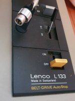
So, I bought a Harman Kardon HD7600 CD player to match up with my HK amp and tuner handed down from my parents, but lo and behold, when it arrived it no longer functioned. Many hours of fruitless searching and trial and error, I have a pretty good idea what's wrong, but I need to find an assembly that doesn't appear to be available anymore (pics below).

Does anyone know where I can get one of these, or even just a replacement spindle?

The player itself appears to work fine, but in its current state it simply spits CDs back out and refuses to play.

Also, is there a forum where I can get help with troubleshooting?

Single gain stage transistor amplifier.

Hi All,

Completely new here,
I've gotten hooked on this DIY audio amp building.
My goal is to replace a Marantz 2226B with a DIY integrated amp. So far I have had good results, but not enough to beat out the Marantz ( it may never happen). I have 90db speakers and can blow go too loud with 4-5 watts. Personally I like lower watts.

So I have tried the Chip amps...but I love the simplicity of a Single ended amp. To me there's no sense in creating a class A/B chip amp if I already have a Class A/B amp...that sounds good.

So I want to find/ develop a circuit that uses a single gain stage single ended transistor amplifier. I had a darlington amp work...but not enough volume. I'm trying to stay away from mosfets- I always come up with more distortion on the simulator with mosfets...and seems to give me a headache when played...awsome transparency though...just too sharp on the highs.

So am I trying to do the impossible? I don't want to rock the windows to a rattle...detail is more important.

Thanks for reading this and for any help you may have.

Solid state R2R attenuator using analog switches or multiplying DAC

I'd like to get opinions on building an attenuator that uses modern analog switches or a multiplying DAC. I've seen this method mentioned a few times and one example of a finished product but it seems it is still rarely done by the DIY community.

After searching through the forums there seems to be a lot of opinions on solid state attenuation but it looks like much of it is not based actual experience. It also seems that analog switches have a reputation that was gained 10 years ago but the analog switches available today are quite different, some having RON of < 1R.

The basic principle seems to be: VI conversion > R2R attenuation > IV conversion. There are quite a few very high end preamps that use this method, eg:
- Mark Levinson 32 and 38 preamps: Pic here.
- Luxman Luxman Electronically Controlled Ultimate Attenuator (LECUA, used is multiple products): Details here
- Accuphase AAVA: Discussed briefly here.

bbp built one, details here and here. Looks like it achieved very good results but he never shared the whole schematic.

While these implementations might sound complex with many analog switches and some ICs to control them, the same can be achieved with a single DAC and Opamp IC. Mark Levinson also does this. BV has mentioned a couple of times that he has achieved good results with DAC8043. It is detailed in the datasheet in figure 3 (VREF is the input):
qpFMHNV.jpg


Here is an Analog Devices Circuit Note about using this method for attenuation: Circuit Note | CN0025 | Precision, AC Reference Signal Attenuator Using the AD5546/AD5556 Multiplying DAC | Analog Devices

The DAC8043 might be good for testing as it comes in a DIP package but there would be better options once it was tested, like using AD5439 with ADuM7440 (SPI isolation) and a OPA1612.

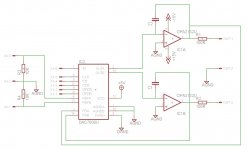
I've attached a schematic using a DAC7800 and a dual opamp.

What do you think? Anyone experimented with this? An SPI controlled 1024 step attenuator that is better and more flexible than a PGA2310 and easier to use than a CS3318?

Attachments

  • Untitled.jpg
    Untitled.jpg
    99.3 KB · Views: 4,234

Amp Design Question

Morning, I’ve been looking at the schematics of B&K and other mosfet architecture amps and it seems each new design had more mosfets. My AV5000 S2 has 4, the AV125.5 that replaced it had 6 and my old REF7250 had 10 per channel. That means to perform the same repair I’ve done to the AV5000 on a REF7250 would be a total of 50 mosfets, for 300 solder joints! Is the increase a matter of making the mosfets work less by splitting the amplification between more components or is there an increased quality of sound by additional power transistors? Or both?

Bi-amping Dali Ikon 6 with a Minidsp 2x4hd?

I've got a pair of Dali Ikon 6 and will be getting a Minidsp 2x4hd- one pair input, two pair output (mid and bass). The Dali have 2 mid drivers and 2 tweeters, and are able to be bi-amped.

Can I sent one output of the minidsp to the tweeters and the other output to the mids? Good idea or bad? I'm new to DSP

edit: sorry if this is the wrong sub-forum. I didn't want to clog up the others with a non-diy question

Power conditioner build

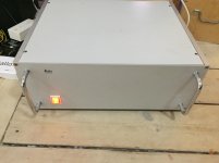
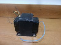
I’ve rescued this old Leitz power supply from a container at work, it was used to power some kind of scientific equipment. Something had leaked inside of it, so I’ve gotten rid of all (weird!) stuff that was inside.

I’m now building a power cleaner out of it instead, and since I'm a complete beginner I could use some comments and help 😱

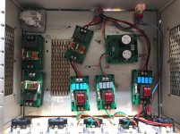
Inside it I now have a number of FO-felix’es. For a little bit of experimenting I’ve set them up differently; the ones with red coils I believe are 3A max (220v), the ones with copper coils are 18A max. The one with ATL written on it is a DC blocker, apparently potentially useful when used with a transformer. 2 of the boards are in line for mounting.

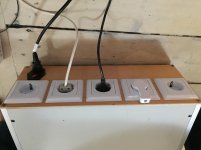
The big challenge I have is that I don’t have and cannot get earth in my apartment. All power outlets are only 2 wires 220v, phase and neutral. Naturally the chassis therefore cannot be earthed either.

All the pcb’s are fitted with nylon stand offs, but they are not yet screwed to the bottom of the enclosure.

I’ve fitted an IEC inlet with a fuse, and every FO-felix also has a fuse (after I bought all parts I’ve come to realize that I can’t even draw 18A from my outlets, so I could have used coils with lower rating but better supression of noise. And the 18A fuses seems to be redundant, as the mains fuse in my apartment would blow before these).

Does it look ok safety wise? Or am I lucky to be alive? Any tips or anything I should pay special attention to? Would safety be better if I used wood for the floor too?

Thanks !

ps1.jpg

ps2.jpg

ps3.jpg

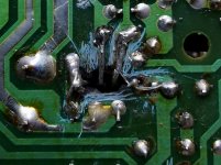
nad 3130 Centre voltage adjustment issue

im having trouble adusting the centre voltage on one channel only, which currently sits outside of the specified ranges of 0v +/- 30mv (currently varying up and down between 40mv and 50mv ) so i dont want to leave it.

the idling current is within limits, so thats ok
soft clipping has no infulence, nor does the impedence switch


with the solder short removed the pot is having no influence.
I have spares of these so ive elimintated that as it is perfect 0-1k


when you turn the amp on it works ok, so its a bit tricky tracing this one
ive checked for all the obvious things visualy, but i dont want to start pulling loads of components out unessesarily unless i realy have to as i could do more harm than good.😕


any ideas?


cheers

Attachments

  • 3130 centre voltage issue.jpg
    3130 centre voltage issue.jpg
    216 KB · Views: 224

very very simple DJ mixer aka summing amp?

Hi there,

I was going through this DIY DJ mixer thread on the forum, and I noticed there was some talk about a very basic DJ mixer set up (mancuso inspired) where say for example: you have two turntables, then you connect the turntables to two phono amps, and then you run that to I guess what would be a summing amp (??) and then run the "resulting" signal to your amp and furthermore speakers.

I thought this was really interesting. The possibility of having a very simple mixer with two stereo channels in and one (maybe another for cueing) stereo channel out as a basic unit which you could then add an isolator or filters to in the output stage could be really great. Because, once you take a DJ mixer and remove all the eqing and effects, you're basically left with a summing amp with phono stages right?

my idea was to just get two really nice phono amps (possibly tube, and yes I'm aware tubes are **** in terms of fidelity, but pleasant coloration can be nice sometimes) and then hook them up to a summing amp and then maybe just get an isolator for the master output if I want to eq it...

So, I guess I'm looking for a simple/reliable summing amp schematic someone out there might recommend. And, also, would this be possible to do with a passive summing box type setup? I don't think so right? why?

Any input is greatly appreciated.

Cheers,
ben

Tubes for sale

Sale:
6J32P — 46 pcs. for $5 ea.
6N6P — 44 pcs. for $3 ea.
6N6P-I — 333 pcs. for $3 ea.
6N8S — 78 pcs. for $2 ea.
6N9S — 9 pcs. for $2 ea.
6N23P — 54 pcs. for $10 ea.
6N23P-EV — 33 pcs. for $20 ea.
6P6S — 84 pcs. for $3.5 ea.
6P14P-EV — 400 pcs. for $10 ea.
6P14P-ER — 400 pcs. for $12 ea.
6P3S-E — 100 pcs. for $7 ea.
6S4S — 13 pcs. for $25 ea.
GS35B — 10 psa. for $100 ea.
GS31B — 7 pcs. for $70 ea.

NAD 7240 PE-state of this.

ive seen some bodge jobs, but go knows how whoever got it like this
its drawing quite a bit of current on the lamp tester, but all fuses are in tact so hopefully i wont have to work too hard with it


biggest challenge is going to be making something reasonable out of whats left of the board

Attachments

  • IMG_20210804_135803.jpg
    IMG_20210804_135803.jpg
    334.1 KB · Views: 170
  • IMG_20210804_141742.jpg
    IMG_20210804_141742.jpg
    255.6 KB · Views: 179

Help assessing a couple of modifications on tritrix TL

Good Morning,

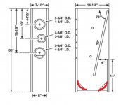
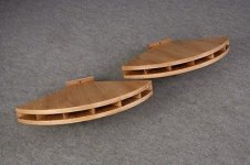
I am brand new to speaker building (so type slowly). All of you are way beyond my ability so laymans terms would be appreciated. My first build is the old TriTrix TL. I have cut my own cabinet per the drawings and few things on Mr. Campbells site. I am trying to figure out how energy travels down the transmission line. I have read it rides on air as a wave, others sites say it moves air. I as a woodworker have the ability to change the 2 corner waveguides that are flat and direct sound like light using 2 mirrors at 45°. I am trying to figure out if rounding them will be beneficial but there are a lot of caveats possible. Should I just leave it alone or is there enough theory of how the energy travels that it will be beneficial? The 2 corner waveguides would be doubled in thickness to achive this and that would change the size of the small chamber it creates (if this chamber is actually active). Do waveguides reflect energy, as in right angles, or does energy travel down them using their sides like RF?

Thanks for any ideas
Donny

.

Attachments

  • cabinet mod 2.jpg
    cabinet mod 2.jpg
    113.5 KB · Views: 93

FS: TOKEN THF-51S NOS

Sold: TOKEN THF-51S NOS

Sold!

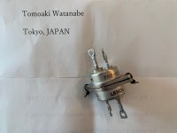
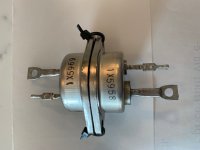
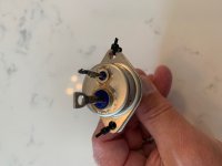
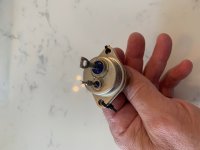
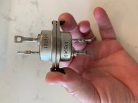
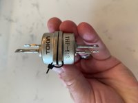
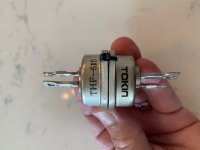
I'm selling a pair of TOKEN THF-51S. These were purchased from watanabetomoaki, a trusted seller of these SITs. They are not matched, but the serial numbers are close, 1X5969 and 1X5958.

I'm selling because I already have a couple of pairs these SITs, one pair in a SissySIT amp and the other pair will be used in the Singing Bush or similar SE amp, and want to fund some other projects.

I'm asking $XXX. The price includes shipping in the USA and PP fees.

Attachments

  • IMG_2515.jpg
    IMG_2515.jpg
    343.1 KB · Views: 217
  • IMG_2516.jpg
    IMG_2516.jpg
    324.6 KB · Views: 213
  • IMG_2517.jpg
    IMG_2517.jpg
    264.4 KB · Views: 204
  • IMG_2518.jpg
    IMG_2518.jpg
    301.3 KB · Views: 202
  • IMG_2519.jpg
    IMG_2519.jpg
    300.6 KB · Views: 201
  • IMG_2520.jpg
    IMG_2520.jpg
    298.2 KB · Views: 74
  • IMG_2521.jpg
    IMG_2521.jpg
    333.5 KB · Views: 64

Denon pma 510ae, static noise in left channel

Ok. Got this Denon pma 510ae amp. It has a low static (white/Pink) noise in left channel, But the music sound fine otherwise. So easiest to hear the noise when there is no music playing. The noise changes when turning the volume knob. Most noise is at about 1/4 volume and 3/4 volume. But when turning on source direct the noise rises more and more the more volume i give it. The signal path is separated in three sections. There are the input section on the main board, and a volume and bass treble balance aso on the front panel PCB connected by i wire . An Its the power stage on the main board. I disconnected the signal wires to the power stage and it became quiet. Its probably not on the main board input side either. I disconnected the left signal wire coming in from the input side and there was still noise. I put another pot parallel to the main pot, no difference. Any ideas what could be the source of the noise? Is it The tone controls?

Attachments

  • IMG_20210711_171503.jpg
    IMG_20210711_171503.jpg
    987 KB · Views: 364

Budget 300B Build Video Series

I am starting on a more adventuresome project, a 300B amp based on the classic JC Morrison 6SN7 design, using a regulated DC power for the heaters.

I understand this is sacred ground I am stepping into, and this irreverent amp I am building, using cheap Edcor iron, I'm sure will draw the ire of some, but I'm doing this for the shear fun of education and the Zen peacefulness of the construction process.

I'm robbing the iron out of a Blueglow/Kegger KT88 build I built, that I'm no longer using. The main expenses at this point is the chassis ($40), some various passives and some 300B-Z tubes with sockets ($225 on sale). I will probably end up in another $100 in misc parts if I don't melt anything in the process.

You can follow along with this build on via this YouTube playlist. Right now I've posted a couple of thought process videos in the planning stages. I've collected most of the parts, and the chassis should be here next week to dive into the metal work.

I have a feeling this one will end up in a different place than my initial planned path, but I do want to stick with a coupled 6SN7 driving a 300B as the end point.

300B DIY Budget Tube Amplifier Build Series - YouTube

DC servo with RC filter question

I am now designing a simple CFA mosfet amplifier that needs a DC servo.

The servo action is injected in the NFB node.

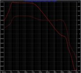
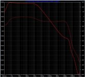
With the servo output unfiltered I am noticing a spike near 3.5Hz in the OLG plot. This spike is accompanied by a phase inversion.

Filtering the output of the servo with an RC (R19 20k and C6 47u) I can greatly reduce the spike and reduce it's frequency (now small peak @ 1.4hz) and phase is not severely inverted.

Increasing the value of this capacitor gives even better results (As an example see the plot with C6 1000uF).

My question is:
Does the RC filter in the output of the servo reduce it's speed ?
How high can I go with the filtering capacitor ?
Is there a drawback in using such servo ?

1st image - Amplifier circuit
2nd image - Servo circuit
3rd image - OLG plot without filtered servo
4th image - OLG plot with 47u filter
5th image - OLG plot with 1000u filter

Attachments

  • CFA amplifier.JPG
    CFA amplifier.JPG
    135.9 KB · Views: 254
  • CFA amplifier SERVO.JPG
    CFA amplifier SERVO.JPG
    51.8 KB · Views: 244
  • OLG without servo filter.JPG
    OLG without servo filter.JPG
    216 KB · Views: 219
  • OLG with servo filter.JPG
    OLG with servo filter.JPG
    223.4 KB · Views: 195
  • OLG with servo 1000uF filter.JPG
    OLG with servo 1000uF filter.JPG
    223 KB · Views: 217

Dumb Cap Substitution Question

I just built a preamp kit (Korg Nutube B1) where 10uF 25V polarized electrolytics were specified for input and output caps. Even though I used Nichicon FG's, I have enough space to plop film caps in there instead.

Assuming the holes in the board are big enough for the film cap lead diameters (big if), is there any reason why I can't swap in film caps for polarized electrolytics?

BLH for Fostex FE168e∑

Hi

i recently build my first pair of small BLH Speaker and i really like them. After listining to them for a while i decided that i need a larger pair for my livingroom. After brwosing through the possible drivers, i decided it have to be the 168ez, i really like the designe (oh and of course the 6,5 inch drivers from Lii Audio but i guess they wont fit in a horn).

Now i am looking for a fitting enclosure. As usually size matters :/ and i have looked for some enclosure suggestions that fit into my living room. I ended up with the following

-BK16 ( according to many people a suboptimal choice)
-The D1 Horn from Nagaoka ( Very similar to the BK16 but a bit larger)
-And the Fostex Suggestion for the FE 166 NV (the 168ez has a sigificantly smaller Vas than the 166 NV)

They all would fit really nice regarding their size but will they sound good with the 168ez ?

Of course i am open for further suggestions 🙂

IR2153 Soft Start

I have a problem with my diy smps for class D. Sometimes a transistor explodes when turned ON. Unfortunately, it also takes circuit 2153 with it. Apparently missing soft start circuit. Runs absolutely reliably when it survives the start.
I need to implement a soft start circuit. I found two similar schematics. Version 1 - via LED to pin1 (Red line in schematic). Version 2 - to pin3 (Blue line in schematic) Please advise me. Which is better?

Thank You.

attachment.php

Attachments

  • spst.jpg
    spst.jpg
    140.9 KB · Views: 18,264

Audio dummy load

For years I've been using a wirewound resistor with some leads and banana plugs as a dummy load for testing amps.

I thought I would buy a proper one but I couldn't find anything pre-made (MCM used to sell one...)

So in case anybody is looking for ideas, here is what I made:

dummyload.jpg


dummyload_inside.jpg


More details here: Audio Dummy Load

The chassis came from Landfall Systems, the extrusion from Heatsink USA, and the resistors (a bargain) at Surplus Sales of Nebraska.

Pete

Where to buy thick diameter cable for DIY RCA interconnects?

Hi all. I've got some rather large RCA plugs that I would like to use, but I can't seem to find any brands of cable that do a big enough overall diameter. The plugs take up to 10mm OD, but all I have are various van damme cables which are only up to 6mm and are too small to be clamped into the large plugs.

I would be most grateful if anyone could let me know where I can buy some 9mm or 10mm unterminated cable for RCA interconnects, preferably online and in the UK.

Thanks in advance.

Port Tuning Frequency & Port Volume

I'm still dumbfounded by the pair of floor-standing speakers I got for free. The driver is a Peerless SKO-165 which claims a resonant frequency of 42Hz. What would you recommend as a port tuning frequency?

The second question is a little more complicated: a single 6.5" driver in a 22 litre cabinet is a waste of space. What are the advantages of increasing port volume? I can attain a frequency of 42Hz with a port of 45 * 90mm. But can achieve the same frequency using 65 * 170mm. What are the advantages of the bigger port.

If you cite WinISD or Hornresp in a brief reply, I'll probably ignore it. In my brain the mention of the aforementioned software translates to 'I don't know'. You see, you are saying, 'There's software for that'. Unfortunately, I comically reminded that several drivers have driven their cars into lakes after blindly following the software.

Unusual Mesh PTP Amp Layout ID?

I've been trying for ages to locate pics and info on this point to point layout. Basically a friend described seeing it somewhere, his description was that all components were set in a wire mesh that stretched across the chassis of the amp, and soldered point to point, and he can't recall where he saw the image. So I don't have much more to go on, but it sounded really interesting, does anyone recognise this vague description? It wasn't a guitar amp. It sounds a bit like an unusual gainclone layout.

Irf3205 reliability?

So I just had a return from an eBay sale on an MTX RT1000D, which apparently shorted a 3205 in the power supply for no apparent reason. This was a S-D short, and it had to have happened at low/idle power since the case of the device was still in perfect condition. Typically if they fail at high power they blow the case apart and melt stuff, this one I didn’t even notice till I put a meter on it. These all came from the same batch, out of the same stick from mouser. Anyone else having reliability issues out there amid this semiconductor shortage?

A very bad Sound-smith retipping experience

I just want to share a very bad experience after trying to get my Clearaudio Concept MC retipped by Sound-smith in NY. The original cart was in a very good but used condition, still sounding very nice but I decided to get it renewed by Soundsmith based on a recommendation. After getting the cart back I noticed a significant channel imbalance but it took me 3 months before actually properly measuring the output of everything in the signal chain. The left channel was clearly 6dB down with both L and R response curves being identical. I asked them to check their work and they accepted that as a warranty claim. At that second inspection the technician (David Moskowitz) said that he found metal debris??, rotated coils and potentially shorted coils in the cart. He initially rendered the cart unfixable, just to come back next day with a message that he cart was fixed and sent back to me. I organised a second cart specialist to inspect the cart and give me his professional opinion. His conclusion was that the original retipping job was not done correctly and that the subsequent fix was just trying to mask the real problem.

I asked Sound-smith for a refund of $450 paid for the service, just to be accused that I caused all the problems with the cart by not using it correctly! Now I do not have the money or the cart that works. I can only advise everyone to be careful next time when you consider them for a retipping job and especially if you end up communicating with their technician David Moskowitz.

CFA Class A Circlotron with stability issues. Thoughts invited.

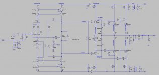
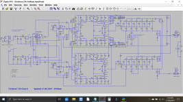
This is a very unusual thread as it is really asking for help/expertise and asking whether anyone can spot any possible issues related to problems that have appeared in real world examples of this design. I know that there is some serious expertise on the forum when it comes to design and build of CFA designs, whether you feel you could offer an opinion or make suggestions 'essentially for free' is up to you. It is quite an interesting circuit though.

It is only fair to say right at the start that only the simulation file is offered and that no other details are available. My only connection in all of this is in having been asked to try and help out.

The file has been produced by another technician working on repairing this amplifier and the people involved in the design and production of the amplifier have agreed to the simulation file being discussed. It has become a problem child.

It appears the design has had issues with 'repeatability' and problems have occurred in service. These typically manifest as high frequency instability and under some circumstances hum and buzzing which appear to be related to the times the amplifier is oscillating. The buzzing reduces as the unit warms.

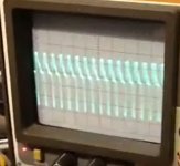
Typically the amplifier may oscillate at power on and although essentially non-destructive it does burn up the 10 ohm in the C/R network across the speaker terminals. This oscillation appears to be in the 300 to 400kHz region and can be picked up on AM radio. This oscillation I believe is in the 16 volt peak region (so I'm assuming over 30 volts across the speaker terminals).

When the amplifier is not oscillating, it can be provoked by simply turning a nearby electrical appliance on/off or by switching from balanced to unbalanced operation. Should the amplifier then burst into oscillation then it seems this is sustained and it can not be stopped unless the power is removed.

There is also a low level higher frequency oscillation (around 5 MHz in the real build) that is visible when the speaker relay is not connected.

The real design seems somewhat critical on semiconductor component types used as fitting different gain groups (for example in the driver stages) changes the nature/frequency of the oscillation but does not provide a fix. Getting the semi's 'right' also seemed to fix the low level hum that some examples had experienced.

(I suspect the hum issue is related to the instability rather than a simple case of hum due to other more mundane reasons)

The simulation file should click and run providing you keep the model file in the same folder. The models are for a handful of devices and are from Bob Cordells site.

Under the upper row of output devices are two resistors used to set the bias current. This allows the user to use a lower power option when needed.

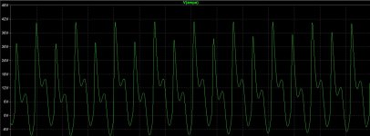
In simulation I have been able to generate very similar looking oscillation to the real world designs by adding a little parasitic inductance (20uH) to the signal feed to Q1 and Q30 base's as shown in the attached image.

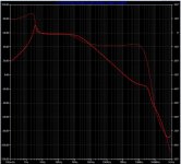
The attached scope shot shows the real problem.

And that is really as far as it has got. Any insight or thoughts that anyone has on this would be welcomed.

Attachments

Clearance around a Behringer DCX?

I'm getting ready to put my system back into action.
I don't have a rack mount and need to knock something up quickly.
Unit is going into a cheap IKEA TV cabinet with only passive ventilation.
I've read the manual several times and if there is information about minimal clearances I have missed it.
Can the members here give me a quick guideline to a good minimum clearance around these units please.
Space is tight or I'd simply allow 1RU top and bottom
Thanx in advance

DSP with Asian ADAU1452 DSP Board+AD1938

Hi guys…

The site is great, and most of it is over my head. But thank you.

I am coming here with my hands help up. Help. I have searches all over. I am a total novice and most things I read have trouble understanding.

The Asian boards do not come well documented, and I have no idea what is in and what is out unless it is obvious. All the boards seem different, and this confuses me.

I have wanted to do DSP and Speaker Cross-over for many years and it is all very complex. I only want to do 2-Way Cross over and Sub. I would really love a digital in and digital our so I can use my own DAC’s.

But I think, please do not shoot me, I think this is an OK combination…ADAU1452 DSP Board+AD1938 Audio CODEC Board+USBi Emulator Burner USB Programmer | eBay

But the seller and other sellers, have no information. I really do know what all the outputs are or how to hook it up or if and where to put power.

Also, I cannot find instructions on how to use these boards with Sigma software to do all the DSP.

I have been looking for over 2 years and I am still confused.

Has anyone used this board and willing to show me??? I am no technical bloke.

Billy Bags Amp Stands,12x12, Matched Pair, Designed for Aleph 2s or Aleph 5

Pair of Billy Bags amp stands. Asking $200 for the pair.


These were designed for the Pass Aleph 2s or Aleph 5, which they fit perfectly, but of course they can be used with other amps. The usable size on the top is 12x12, with the rails adding an inch or so on each side.

I'm willing to sell just one, if you have an Aleph 5, but I'd much prefer to sell them together.

I do not have boxes for these (obviously, really, right?) so would prefer something local. But I can certainly cobble something together for shipping. I'd recommend a little plywood crate, as they are heavy and will not play well with cardboard, I don't think. (I can do that easily enough. I've got lots of plywood lying around.) That's why I've set the shipping weight to 20lbs. But shipping cost will be whatever the actual cost is, to be worked out between me and the seller.

PC Hum/HDD noise into preamplifier

I am looking for help to solve a small amount of noise, consistant with HDD operation, mouse movements, etc... Heard at the speaker and enough to be annoying.
Set up is an Elekit Amp and Elekit Pre-amp, turntable and PC, with RCA out> into the Pre-amp. When listening to vinyl there is absolutey no noise, it's perfect. If I decide to listen from the PC (J-river/Flac), i.e. use a different input at the pre-amp, there is annoying humm as above. I have a power board that filters and everything is plugged into the same board from 1 AC outlet. I have tried a few of the ferrite chokes on the power cords to no avail. Pulled the PC apart and looking at the sound card, chassis, etc... I can see little screws that appear to earth everything as it should. Looked around on the forum and wouldn't know where to add a wire to stop a ground loop, if that is the issue, from occurring.
It is a recently built PC with a EV brand sound card.
My question possibly is, if the noise can't be solved, is it easier to purchase something that will use SPIF/Toslink (PC has this) in and RCA out (to the pre-amp), that doesn't reduce the sound quality, and get around the noise issue that way, or is there more I can do to solve to problem at it's source, i.e. in the PC.
I can add images of the PC internals, etc.. if that helps.
All help appreciated as I'm fairly new to the audio world.

James

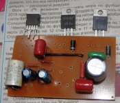
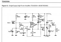
TDA2030 with transistors

Hi there!
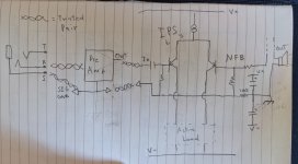
I decided to try scematic TDA2030 as a tranzistor driver. And i have some questions about that schematic.
Did anyone do such a scheme? Does it sound normal? Will that schematic give me some troubles with installation and tuning?
Starting at what output power will additional transistors begin working?
What power supply unit should I use? How many watts?
And in this scheme, the gain factor is 10 as I understand it. Is this enough for an input signal level of 500 mV? What values of pR4 and R5 should I use?
I will definitely try this scheme. I already made a circuit board and almost soldered all the components.

Attachments

  • P3310064.JPG
    P3310064.JPG
    732.6 KB · Views: 1,589
  • P3310068.JPG
    P3310068.JPG
    916.3 KB · Views: 1,387
  • P3310066.jpg
    P3310066.jpg
    216.7 KB · Views: 1,395
  • Снимок.JPG
    Снимок.JPG
    73.3 KB · Views: 1,560

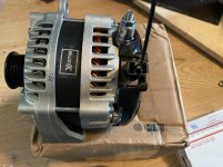
High Output Alternator

I’m finishing up my stereo system in my truck .

The last thing I need to do is install the high output alternator and battery bank .


I will be running this alternator separate so it only charges the back battery and will have nothing to do with the stock charging system this is a stand alone alt .

I tried contacting the manufacturer but never heard back .

This alternator has a external regulator.

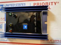
Here are some pics but it’s been awhile since I hooked up systems .

My question is

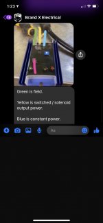
1 terminal of the regulator goes to constant power
Another Terminal goes to ground

Then there is a terminal that goes to the field
And last terminal goes to switched power/solenoid output power .

The plug on the alternator has only 1 wire coming out .

So the question is what is the field wire ?
And what is the switched power/solenoid output ?

Wondering how I hook this up ?

I need to know what to hook the wire coming out of alt goes to
What the field wire goes to ?
And the switched power/ solenoid output goes to ?

Any info would greatly be appreciated

Attachments

  • B5E3E603-0197-46C7-B9BD-3B13B52D580D.jpg
    B5E3E603-0197-46C7-B9BD-3B13B52D580D.jpg
    993 KB · Views: 137
  • B08429B7-2C83-41B1-A9C2-0823B0066924.jpg
    B08429B7-2C83-41B1-A9C2-0823B0066924.jpg
    918.2 KB · Views: 138
  • 1ED21E8B-10B0-4931-A6BE-F8A1AD9496C6.jpg
    1ED21E8B-10B0-4931-A6BE-F8A1AD9496C6.jpg
    74 KB · Views: 140

Signal Ground Question

I've been preparing for my next build, and wanted to get the whole signal grounding thing right. I have Doug Self's book, and I have been referring to Fig 25.1 on page 600 (6th ed). I'm not sure if I'm allowed to post that here, but it is a helpful diagram.

I wanted to draw it out and see if it made sense to me, and hear if anyone has any suggestions.

My main takeaways are:


1. Local rail decoupling capacitors need to have ground at star point
2. Speaker return have ground at star point
3. NFB ground should be with signal ground


My main points of confusion:


1. In preamp, do I add an additional return path for signal ground to PSU ground on its PCB? Or, do I only allow preamp signal ground to be returned through the main amp unit and its star point? In the picture, there is no connection to signal ground to PSU ground that comes in with supply rails.
2. Is the 100 ohm resistor that separates signal ground and PSU ground at the star point necessary?


"drawing" 😱 is attached, appreciate any feedback/discussion. Thank you!

Attachments

  • PXL_20210722_204325312.jpg
    PXL_20210722_204325312.jpg
    638 KB · Views: 685

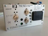
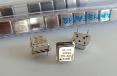
[Europe] FS/FT Various parts / NOS DAC MOSFET XO PSU...

Attachments

  • Alim_LAB_DSL_POTS.jpg
    Alim_LAB_DSL_POTS.jpg
    392.1 KB · Views: 234
  • CXO-48MHZ.jpg
    CXO-48MHZ.jpg
    179.9 KB · Views: 253
  • LEMO.jpg
    LEMO.jpg
    628.9 KB · Views: 239
  • LUMBERG.jpg
    LUMBERG.jpg
    443 KB · Views: 233
  • TAMURA_6.3x1.25VA.jpg
    TAMURA_6.3x1.25VA.jpg
    278.6 KB · Views: 242
  • P6NB80_Power_MOSFET.jpg
    P6NB80_Power_MOSFET.jpg
    178.1 KB · Views: 152
  • B7NK80_Power_MOSFET.jpg
    B7NK80_Power_MOSFET.jpg
    222.5 KB · Views: 140
  • LM2596_DC-DC.jpg
    LM2596_DC-DC.jpg
    252.4 KB · Views: 135
  • BB_DAC7644.jpg
    BB_DAC7644.jpg
    158.9 KB · Views: 134

another JL 500/1 - no power, no output

This amp was previously working, today it seems to have quit.

Be aware I've been using this amp with faulty supply wiring. Fused distribution block had a loose internal connection. This was discovered and repaired as of today.


JL 500/1, main board revision 10


Tested 10-pin connector.


Supply voltage: regulated 14.2v from bench power.
Pin 1: 0.0
Pin 2: 0.0
Pin 3: 0.54 v
Pin 4: 5.65v
Pin 5: 145 mV
Pin 6: 14.15 V
Pin 7: 0.0
Pin 8: 40.2 mV
Pin 9: 192.3 mV
Pin 10: 0.0


PCB looks pristine. No burnt soot, no bulging caps, no hot spots that I can identify.


Other than double checking power leads, I'm unsure how to proceed. Any guidance is appreciated.

Application of golomb rulers to sparse line arrays

Inspired by this...

"Dipol 08" Baffle Dimension and List of Crossover Parts

I decided to do my own open baffle golomb line array.

A lot of testing with previous prototypes showed that I want a narrow but long/high open baffle line array without any power or frequency tapering.
I decided to try eight units per side.

Perhaps the following will help somebody struggling with the application of the golomb ruler to such a so called sparse line array.

I found some statements that it is impossible to apply the ruler to a bigger number of speakers assuming that the base unit of the ruler needs to be the speakers vertical dimension.
So a 8 speaker golomb line array made of 10cm speakers will have a total height of 340cm because an order 8 golomb rulers length is 34.

Golomb ruler - Wikipedia

But this is a too narrow interpretation of the Golomb ruler.
Golomb rulers help to get an optimal distribution of units over a given length e.g. where you do not have enough units to cover the entire length (sparse line array).
"Optimal" means that the DISTANCE between ANY two units in the array is UNIQUE.
It is all about the distances not the values or the ruler

distributed.net: Project OGR

The 8 unit golomb rulers values are
0 1 4 9 15 22 32 34
which is written as distances
1 - 3 - 5 - 6 - 7 - 10 - 2 (= 34)

The room height is 250 cm
I wanted a line array that is at least 70% of the height and decided to make the array 180 cm high.
The speakers vertical dimension is 12cm x 8 speakers = 96cm covered by the speakers.
So there are 84cm left of my baffle
Divided spare room by the ruler length of 34 = 2.5cm
This "base unit" is multiplied with the golomb distances between the units,
e.g. from 0 to 1 = 1 * 2.5, from 1 to 4 = 3 * 2.5, etc.

Finally added arbitrarily 4 cm on top and bottom of the baffle just to have something to fix the thing somewhere.
The center of the array is at listening height.

754818d1557158340-ultimate-baffle-gallery-dipolv4_all-jpg


I attached the DSP settings and measurements at different distances and heigths
They show that the speakers melt nicely together at about 350cm distance which is my listening position.

Attachments

  • line_array_dist_150cm_diff_heights.JPG
    line_array_dist_150cm_diff_heights.JPG
    104.8 KB · Views: 461
  • line_array_dist_250cm_diff_heights.JPG
    line_array_dist_250cm_diff_heights.JPG
    107 KB · Views: 446
  • line_array_dist_350cm_diff_heights.JPG
    line_array_dist_350cm_diff_heights.JPG
    106.3 KB · Views: 448
  • reckhorn_curves.JPG
    reckhorn_curves.JPG
    101.6 KB · Views: 459
  • Like
Reactions: Naturlyd

volume control relè

Hi everyone.
I'm trying to design and build a simple relay volume control. I would like to do it with the requirements that I am going to list below:
- simplicity
- pure electronics, no PIC, microcontroller, firmware and software.
- easy to repair in case of failure
- single entrance
- remotely controlled with Ir or RF remote control
- no display in my opinion is not needed.
- no SMD but integrated with base so you can replace them without unsoldering.
- silent
- each relay of the signal group must have two separate contacts to obtain two channels
- functions: increase / decrease, mute / restore, storage of the volume prior to switching off.

I have already prepared the heart of the circuit but I ask you for some advice on choosing the components.
- which relays to use for the signal to obtain silence and long life?
- which single coil bistable relays to use to obtain silence and
lasting in time?
- which resistances to use?
- which configuration do you recommend to use for the resistance chain
? series? shunt? ladder?
- how to neutralize the micro-bounces of the relay contacts?
- which system to use to avoid overlapping two volumes
when do you change? I thought of inserting a small delay circuit when the relay is switched on. what would you do?

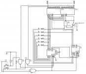
I briefly describe the circuit I have attached.
the two counters in cascade CD40193 have 2 inputs to increase or decrease, they control two 74HC154 and the outputs of the latter go to control the relays dedicated to the signal.
by enabling or disabling the two inputs E2 of the 74HC154 the mute / reset function is obtained.
the NAND U1 gate has the function of updating the outputs with the inputs of the CD40193 at power on, through the LOAD input.
the six bistable relays have the function of memorizing the volume prior to switching off.
of course the circuit is not complete, the remote control circuit is missing, the one that controls the bistable relays, the delay circuit of the signal relays.
Invia commenti
Cronologia
Salvate
Community

Attachments

  • controllo volume.jpg
    controllo volume.jpg
    137.4 KB · Views: 774

multiple soundcards as active processor for HT?

I'm planning to build a 5.1 surround system for my home theater (see thread http://www.diyaudio.com/forums/everything-else/282286-diy-home-theatre-where-start.html) with all active crossover and individual amplification. 3 way frontstage and 2-way rear surround

A friend of mine built a carputer about 10yrs ago where he would use the different output of a surround sound car to drive active 3-way frontstage. Would it be possible to do the same thing with an home theater? If it has been done, what kind of equipment would be adequate?

smd soldering in the EU

Hey there diyaudio community,


my fine motor skills lately just aren't what they used to be. However, I have some unpopulated PCB's and all needed parts laying around for quite some time now and would really like to at least have the DAC finished, but it would take me forever with my shaky hands right now. They are good enough for soldering point-to-point or trough-hole, but just not for those teeny-tiny smd parts.


Does anyone have experience with a PCB assembly ~smd-soldering~ service in the EU?
Or better, would maybe a member on here be so kind and do the smd soldering job? Against payment of course or maybe a payment plus NOS tubes, chokes, transformers or other parts I intend to sell somewhen anyhow.


Any help is greatly appreciated and I hope this is the right sector -otherwise please move it to the correct one.


Thanks,
Brzzl

DOD 834 Series II active crossover

Hi folks

I'm having no end of trouble trying to get my new active crossover setup working.

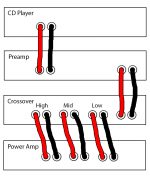
I have a NAD 1000 Preamp feeding into a DOD 834 Series II active crossover which splits the signal into Hi, Med and Low, which I am then feeding to a Sonance Sonamp 1230 power amp working in bridge mode to give 6 channels.

The problem is that when connected as below, with cables I made that have a mono 6.35mm jack on one end and a male phono on the other, I am only getting sound through one channel.

I've verified with a multimeter that all the cables are working properly.

If I press the stereo-mono switch on the front of the DOD 834, it changes the behaviour, it appears that now, the highs are on one channel and the lows on another.

I'm most confused, I can't for the life of me figure out what is wrong.

Attachments

  • Bridged 4.png
    Bridged 4.png
    69.3 KB · Views: 226

HT room with a large openning

Hey guys...

We have a HT room in a duplex house.
Room size is 20X14X11ft.

The room is not completely closed, because there is a large opening (6ft x 11ft) for the stair case that connects ground floor and first floor.

How necessary is it to close this openning for pressurizing the room with tactile movie bass?? (Basically install a big door)

Is it possible to pressurize the room that has a big openning ??

Quadratic/Skyline diffuser questions.

A friend of mine has been asking me about building him either some quadratic or skyline diffusers. He lined every wall in his listening space with acoustic panels and he's now decided he doesn't like how dull it sounds.

I purchased a book detailing the BBC designs of diffusers and figured that would be a good place to start. He's asking about making some pretty large panels to hang from his 10' ceilings, 4x8' size panels.

My question for anyone whom might know is. Are the size of these types of diffusers scalable?

For example if a quadratic diffuser calls for a 4x4" square well, can that be expanded to a 6x6" square well?

Or in the case of a skyline style diffuser where plans call for 2x2" blocks at different heights. Can that be scaled to say a 4x4" block and still use the same heights outlined in the plans for 2x2" blocks?

Most of these designs make a roughly 2x2' panel, if I were to expand this to 4x4' instead of essentially making 4, 2x2' panels can these designs be scaled to accommodate a larger size panel?

Protection Circuit - Crowbar - Zener vs SBS

Hi

I have bee looking at crowbar circuits and came across this thread. In it is decribed the dc protection circuit used on the quad 405. It uses a Silicon Bilateral Switch to activate a triac which then shorts the amp out. It also contain a filter network to ensure the thing doesn't trigger all the time.

My question here is simple. What advantage in this instance does the SBS hold over a zener? The only thing that I can see is that it may be a bit more accurate with the "trigger voltage", but surely this voltage does not realy matter.

The reason I ask is that these SBS's are horrendously expensive but at the same time I am convinced that quad must have made this decision for a reason.

The Intellectual People Podcast - JDS Labs

John Seaber set out on a mission. He wanted a well performing headphone amp. Little did he know that his search would form a very successful business manufacturing an enhanced version of Chu Moy's cMoy design. Selling tens of thousands of these units, yes, you read that right; ultimately led to his own design. His story is quite neat to listen to. Enjoy!

How did NwAvGuy help JDS Labs? | John from JDS Labs | Ep 37 - YouTube

Attachments

  • JDS Labs Thumbnail.jpg
    JDS Labs Thumbnail.jpg
    86.3 KB · Views: 106

FS: Several drivers. Another clearance

Time for another clearance:

2x SBAcoustics SB17MFC35-8 midwoofers. NOW SOLD.


2x SBAcoustics SB26STCN-C000-4 tweeters. NOW SOLD.


2x HIVI TM1A tweeter + midrange. In their original box. Never used. Bought 4 months ago and opened just for pictures.
Asking 60€ for the pair.


2x HIFIDIY AL-100 AMT tweeters. In their original box. Never used. Bought 4 months ago and opened just for pictures.
Asking 20€ for the pair.


2x Audaphon MB18-8 midwoofers. Used but in very good condition. An incredible well built unit.
Retail 50€ each. Asking 50€ for the pair.


2x SEAS 27TDFC H1189-06 Tweeters.
SOLD.

Paypal fees and shipping not included.
For several units price will be dropped.
Questions, please, PM me.

Pair of top of the line carbon fiber woofers with 4 inch magnet

These are a pair of woofers from emerald physics top of the line open baffle

carbon fiber
huge spider
largest magent

made by eminence

pictures: Emerald physics 4.4 - Album on Imgur

this ad is for just the pair of woofers

i;m giving the woofers away for free but whether i have to do two boxes or one box you have to pay for all packing and shipping cost via UPS

6SN7 > 6SN7 > 300B , 6SN7 DC 300B

Hi DIYers,

I am working on an unique directed coupled 300B amp.

All triodes are common cathode configuration.

2 stage 6SN7 amplification, first stage 6SN7 and second stage are capacitance coupled, second stage 6SN7 and 300B are direct coupled.

I don't use high watt resistance to raise cathode voltage of 300B, instead I use negative voltage supply for second stage 6SN7.

I use 866A tube in B+ and EY84 in B-

All parts and chassis are ready for assembly.

Happy to hear your comments!

Coral Beta rubbing voice coil / cloth surrounds

When further listening to my newly arrived and otherwise good sounding Coral Beta 10Bs, I noticed a buzzing sound on certain bass notes (mainly lower cello and middle electric bass). When I unplugged the buzzing driver and gently pushed the cone inwards, I heard a rubbing sound. Very scary. Only if I pushed it to one side however. I suspect that either the voice coil is damaged, or I need to re-align it. Maybe both. Anyhow, I need to somehow remove/release the cloth surrounds and spider. Anyone done this before? What type of glue can I use to stick the surround to the frame again, if I manage to salvage it? Also, is there a place where I can buy new white cloth surrounds for a 10" speaker?

JL Audio ProWedge CS212OG-W6v3 vs JL Audio CLS110RG-W7AE

Hi, 1st post! Got a burning question which has been asked to death. As per title, can't decide on the above. Please help. & it has to be these 2 only strictly from JL Audio.

-1st option is 2 x 12W6v3 subs in a dual opposed sealed JL enclosure powered by an HD 1200/1 amp - JL Audio ProWedge CS212OG-W6v3

-2nd option is a 10W7 sub in a sealed JL enclosure powered by an HD 750/1 amp - JL Audio CLS110RG-W7AE

The car is a Mercedes Benz CLS63 Shooting Brake :car:

Sound Quality is my main priority and saving boot space. I've heard that the 12W6v3-4 sounds better than the 10W7 but others say they all sound good.

I rarely listen at reference loudness - mid volume mostly. I still want to be thumped in the chest or massaged by bass though when in the mood!!

The 10w7 would occupy slightly less space & also cost a bit less. I suspect the 2 X 12W6v3 may have more control and composure as its rated at 1200 watts vs 750watts for the 10W7.

Obviously the 1st option has more cone area and will be working less comparatively. But the 10W7 has 23mm x-max vs 19mm for the 12W6v3

I appreciate that custom enclosures may yield better results as they're bigger than JL Audio's apparently conservative sizes. But it has to be from the above JL's enclosures as I will be changing cars next year. Decisions, decisions, decisions... Thank you in advance 🙂

10W7AE-3

Free Air Resonance (Fs) 30.6 Hz
Electrical “Q” (Qes) 0.578
Mechanical “Q” (Qms) 7.647
Total Speaker “Q” (Qts) 0.537
Equivalent Compliance (Vas) 1.28 cu ft / 36.1 L
One-Way Linear Excursion (Xmax)* 0.9 in / 23 mm
Reference Efficiency (no) 0.17%
Efficiency (1 W / 1 m)** 84.3 dB SPL
Effective Piston Area (Sd) 59.8 sq in / 0.0386 sq m
DC Resistance (Re) 2.75 Ω

12W6v3-4
Free Air Resonance (Fs) 26.919 Hz
Electrical “Q” (Qes) 0.487
Mechanical “Q” (Qms) 9.365
Total Speaker “Q” (Qts) 0.463
Equivalent Compliance (Vas) 1.920 cu ft / 54.37 L
One-Way Linear Excursion (Xmax)* 0.75 in / 19 mm
Reference Efficiency (no) 0.11%
Efficiency (1 W / 1 m)** 85.4 dB SPL
Effective Piston Area (Sd) 75.338 sq in / 0.0486 sq m
DC Resistance (Re)*** 6.493 Ω

DIY Subwoofer Design help

Hi there,

I have an 18" Mackie branded (but built by Eminence) driver laying around that I got off a friend a while ago. I would like to build a box for it to put it to use, and so I put the T/S parameters into WinISD. It defaulted to an absolutely massive 17.3 cubic foot box, which does not seem correct - or is it?

The parameters are as follows:

Re 3.20 Ohms fs 38.3 Hz
Le 0.72 mH Mms 145.5 grams
QM 8.03 Mmd 122.0 grams
QE 0.51 Cms 0.119 mm/N
QT 0.48 Rms 4.354 N*sec/m
Xmax 6.67 mm Vas 238.4 liters
Pmax 450 Watts SD 1188.0 cm^2
Bl 14.85 Tm VD 792.1 cm^3
Coil Diameter 4.00 Inches EBP 75.3
Gap Height 0.375 Inches Magnet Weight 109 ounces
Efficiency 2.54 % Winding Width 0.900 inches
SPL 96.1 dB 1W-1m

Could someone please tell me if i'm doing something wrong? Or would you recommend to just get a new driver.

Thanks,
Joe
Projects by fanatics, for fanatics
Get answers and advice for everyone wanting to learn the art of audio.
Join the Community
507,624
Members
7,880,643
Messages

Filter

Forum Statistics

Threads
405,890
Messages
7,880,643
Members
507,624
Latest member
Neilonpoint