Mid Range Speaker Recommendations

Hello,
I'm currently designing my first speaker built or new HT, but I have a difficulty to select a mid range driver which is able to sustain good flat response between 400Mhz - 4kHZ. Re tweeter I'm homing for Vifa xt25bg60 which seems to have a good response. And for the woofers I'm considering Epique E150HE-44 5-1/2"

The idea is to build a 3 way tower speakers and a center speaker LCR.

Any suggestions for good mid range?

ES9038PRO DIYINHK

Hello guys, want make dac on this board.
Maybe some one has experiense of building?

I have some question, maybe someone can give me a advise:

1. Capacitors around chip, NP0 ceramic will be ok?
2. Oscillator NDK NZ2520SD will be ok?
3. KEMET Aluminium Organic Polymer Capacitor will be on on digital supply?
On analog supply will be elna silmic II.
4. Power stabilizers LT1963? Or need extreme low noise LT3042?
5. ES9038 have high output current in mono mode, which op amplifier which
one to prefer?
OPA1688 :75mA, OPA1612:55mA, OPA1622:145mA
6. otput stade capacitors xicol polystyrene, dale resistors?
7. I think don't used a I2C controller because PCM/DSD and I2S/SPDIF
switch automaticaly?

4253153527da.jpg
[/url][/IMG]

b3fc9cf8a2f8.jpg
[/url][/IMG]

6fe8e4a70287.jpg
[/url][/IMG]

What should I upgrade or replace as part of a restoration project (Hafler DH-220)?

I've been working on a Hafler DH-220 as a learning project. I just got it back to operating condition (yay!) and I want to finish the project by cleaning up the wiring, replacing the connection hardware, and replacing or upgrading as many of the caps or other parts that are deemed worth it.

Currently I plan on replacing the power filter caps with higher capacity Nippon capacitors. I plan to replace the electrolytic caps on the driver boards, but I haven't selected a brand yet. I'm considering replacing more of the capacitors, but I haven't identified a clear reason to do so, or a brand to use if I do.

Any suggestions for vectors for improvement, either reliability or sonically?

Some other Source Follower Configurations

I have been thinking about some other configurations than the 3 classics published in Borbely's article JFETS : New Frontiers. I hope I did not re-invent the wheel by accident.

To avoid any trouble with copyright issues, here are the links to figures or circuits referred to in the article :


http://www.borbelyaudio.com/adobe/ae699bor.pdf

http://www.analogzone.com/col_01302004.pdf

http://www.diyaudio.com/forums/head...dphone-amplifier-post1130743.html#post1130743

http://www.diyaudio.com/forums/soli...rch-preamplifier-post1507926.html#post1507926

Taylor Source Follower

http://www.passdiy.com/pdf/zen-ver2.pdf


Enjoy. 😉


Patrick

Non USB streaming options

Apologies if this subject has already been covered and I have not managed to locate it it. I have almost convinced myself that I want a streaming option that does not include USB connectivity. Now before I go any further I should be clear and say I have only ever streamed Tidal using my inexpensive Activo CT-10.

I have everything I need to go to the next USB stage of streaming, a new fanless PC, master clock, 2 new Mirage USB cables. But at the back of my mind there is the constant thought that I will get a better sound by building a streaming rig that avoids USB connectivity however I still have a lot to learn on this front, hence this post.

Right now I am attracted to the idea of Raspberry Pi4 combined with a Pi2AES but I am more than happy to consider other options. IS2 connectivity is also an option as I am going to upgrade my Ares2 to a Pontus2 in late September. Any advice & thoughts are welcome, even critical ones 😉 Thanks PB

Good sounding and fitting Truly Wireless Earbuds.

Hi team,

having recently purchased a pair of Samsung Galaxy Buds Pro true wireless earbuds, for their convenience, and ease of use. While they sound acceptable, I CAN NOT get them to stay in my ears, it is HIGHLY frustrating. This is not even anything strenuous, like running, or skipping etc.

My question is, what are people's experiences with fitment and DEFINITELY sound from True Wireless Earbuds?

In the perfect World there MUST be a set of good sounding earbuds that stay in place during running?

I appreciate anyone's input.

Ideas for a 47 SE amp in pentode mode.

Lately I got a bug to build a fleapower amp using the early globe style 5 pin tubes. I picked up a pair of RCA 47 and a pair of 27 tubes and have a pair of 8W 7K OT. Probably going to get a matching globe type 80 rectifier to go with it. Not seeing much online as far as schematics, but it shouldn't be too hard to come up with something. I think this will be a fun project!

Anyone have some ideas or seen schematics for using these early tubes?

Audio Engineering Components ARA-412-27-G?

I've got an opportunity to pick one of these up, cheap. There's precious little about it on the web - basically one ad from a 1978 issue of Recording Engineering and Producing (?) magazine.

Looks like an RTA built around a small CRT oscilloscope; they also made a version that would plug into your own scope, for $1500 less. Appears to be about 6RU tall.

Does anyone know anything about this device, or this company? They've still got a web presence as part of Audio Intl., but there's nothing about this or anything like it. It apparently still works, so I figure if nothing else it can be an interesting conversation piece.

Attachments

  • Screenshot_20210827-175215_Drive.jpg
    Screenshot_20210827-175215_Drive.jpg
    734.9 KB · Views: 126

Neo3-Off BG vs GR vs Sounderlink

I just got the 2x Sounderlink Neo3PDR from aliexpress and decided to measure some:

The drivers measured are:

2x Sounderlink Neo3PDR
1x BG Neo3PDR
2x GR Neo3 (no felt on sides, so more similar to Neo3W)

The setup is at 50 cm distance with SPL calibrated with an an SPL meter to -6 dB to be equivilent to 0 dB @ 1m. The drivers were measured in free air nude in dipole mode.

ALL drivers were driven with 1 2khz LR2 highpass. No individual EQ was applied for any driver.

All in all the Sounderlinks measure really well, they are more efficient than the BG and have comparable distortion but in my sample of 2 the consistency is garbage. If you run an active setup with DSP and one channel for each and you measure and apply EQ for each speaker individually then they seem perfectly usable.

The GR Neo3s are extremely efficient, but I did not expect them to have that much distortion. I was suprised hence why I hooked up my other tweeter. And even when reduced by -3 dB to 0.7W it still distorts more at the same SPL. One difference though is that I did solder the terminals on the GR but quick, carefully and with 1mm wire.

Attachments

  • Sounderlink Neo3PDR #1 1W.png
    Sounderlink Neo3PDR #1 1W.png
    189.6 KB · Views: 1,562
  • Sounderlink Neo3PDR #2 1W.png
    Sounderlink Neo3PDR #2 1W.png
    189.7 KB · Views: 1,534
  • BG Neo3PDR #1 1W.png
    BG Neo3PDR #1 1W.png
    182.6 KB · Views: 1,502
  • GR Neo3 #1 1W.png
    GR Neo3 #1 1W.png
    200.4 KB · Views: 1,511
  • GR Neo3 #1 0.7W.png
    GR Neo3 #1 0.7W.png
    199.9 KB · Views: 1,473
  • GR Neo3 #2 1W.png
    GR Neo3 #2 1W.png
    207.8 KB · Views: 619
  • GR Neo3 #2 0.7W.png
    GR Neo3 #2 0.7W.png
    203.2 KB · Views: 671
  • DSC_0460.jpg
    DSC_0460.jpg
    985 KB · Views: 800
  • Like
Reactions: ScottG

NAD 304 not powering up

Hi all,
I've got a non functional NAD 304 for free in order to repair it.
The owner said that it suddenly stopped working in the middle of a party.
I thought it'd be a simple fix like a power supply issue/fuse or even some kind of overload protection kicking in because of a short but it turns out I might have an open primary on the power transformer.

I desoldered the secondary of the transformer going to the board and tried to power it up with no luck.

I even tried to power it up (with a lamp in series) directly from the primary (bypassing the switch) but again no signs of life.

I get absolutely no ohm reading (OL) between the red (hot) and neutral (black) of the primary.

The transformer has other windings for 110V operation but I only tried the 220V so far.

I might try the 110V taps too which might be okay but I'm very curious what might be the issue here.

I opened up the transformer (broke the external shield plate and removed the insulating tape) and nothing seems or smells like it's burned up.The enamel wire seems okay so I suspected a thermal fuse might have opened.

Thing is there is no thermal fuse there (not within reach anyways) so it's kind of strange that the transformer primary "opened" with no signs of overheating etc..

Does anyone know if that's really the case with these amps?

4 transistor preamp, -100db thd floor

It's time to play "transistor golf." Here's a simple preamp using four bipolars. It simulates better than -100db distortion floor in the worst case (20kHz large signal) and less at more typical conditions.

This is a mod of a Sanyo JCX-2600K preamp on the factory PCB, and four transistors is all it had room for. (From the factory, the circuit has only 2 bipolars and simulates to around a -80db distortion floor -- which is no better at mid-band than at 20kHz.)

If there were budget for a 5th transistor, it would be nice to cascode the input transistor to defeat any early effect and nonlinear Cob. Those effects show up since source impedance is high (100k volume pot.) Regardless, simulation suggests these effects aren't too bad.

Here's the circuit and loopgain plot. Two-pole compensation yields >70db of feedback for most of the audio band, dipping to 60db only in the top octave. There's gobs of stability -- 70 degrees of phase margin and >30db of gain margin.

Attachments

  • sanyo_pre.png
    sanyo_pre.png
    79 KB · Views: 698
  • sanyo_pre_loopgain.png
    sanyo_pre_loopgain.png
    53.8 KB · Views: 682

VU Meter Driver

Hello All,

I have always loved the look of analogue VU meters on an amp, so I’ve purchased a kit from eBay that includes this board. Admittedly it is more for the visual entertainment as opposed to function and I may just have it hooked up to my preamp output.

TA7318P VU Meter Driver Circuit Board Stereo Module Tube Amplifier DB Level IC 889970793033 | eBay

The unit has low level inputs to be driven from a pre amp as well as high level inputs for speaker output level measurement. There is not a lot of info or instructions for the board and the sellers information is translated to English, so it is not very clear and my interpretation of the info is a guess at best. Some research from google has indicated though that the high level inputs should only be used on an amplifier that has a negative speaker connection with a ground reference type which I believe the Aleph J and other first watt projects are. A poster on another site drew out the schematic below. My question is if anyone thinks this connection would damage the output of my aleph J or M2x? My curiosity about hooking it up to the speaker outputs is out of curiosity to see what my amp may actually be outputting when cranked up.

Thanks!

Attachments

  • FEADEF13-67DE-4D1D-A3E8-8C7E6B536A0E.jpeg
    FEADEF13-67DE-4D1D-A3E8-8C7E6B536A0E.jpeg
    377.6 KB · Views: 2,304

Which way to build opposed?

I am building an wall unit for TV and audio, and one set of cabinets will be the bottom of a three way that will essentially be subs (but may extend a bit into woofer frequencies depending on testing & where I decide to put the XO.) The other 2 in the 3 way are 8" Scan 22W/4534g woofer into an SB26ADC tweeter in an AugerPro waveguide. This will all be playing into an open concept living room / dining room / kitchen type space that is nearly 1000 sq ft. and a total nightmare for audio (hardwood floors, smooth ceiling, hardwood shutters.) I got what concessions I could in terms of WAF, and this is where I ended up.

Current plan for the bottom end is 2xSB34NRXL opposed on each side, but have not yet bought the woofers yet, so driver is flexible. The 2 ways on top are currently built as large bookshelf style speakers until I get this thing built and then they'll build into the solid panel in the outer bookshelves as seen in the "innie" picture. There is a ~7" deep cavity behind the TV that hides approx 250L / 9cu ft per side after taking into account the bracing. Plan is to build with a port tuned to 16-18Hz and have the option to experiment with both ported and sealed configurations. Each side is powered by a Hypex FA253, so I can use the DSP to tune in the FR for an F3/F6/F10 much lower than the natural tuning.

I can build these in an "innie" or "outie" configuration (see pictures). Both have similar outward facing manifold area per speaker, and both will be covered by grille cloth so that aesthetics are not a part of the equation. I can get the drivers braced together better & the slot port is easier to build in the "outie" config, but the "innie" config seems like it would be the traditional way to build a manifold like this.

Will it make much of a difference either way? Is there a compelling reason to build it one way or another outside of how well the drivers are coupled together? Both variants can use threaded rod through both drivers, but in the "outie" config I can also brace the magnets together.

Attachments

  • Variant1--innie.png
    Variant1--innie.png
    29.9 KB · Views: 125
  • Variant2--outie.png
    Variant2--outie.png
    28.8 KB · Views: 122

TDA8932 2 x 15w... connections

Hi there I need some professional help with an amp board that I bought from Ebay…
Digital TDA8932 Amplifier Board 2x 15w
Digital TDA8932 Amplifier Board 15W/30W/35W Mono Amplifier Module Low Power NEW | eBay


information from the site says ….” Speaker Interface: 2.0mm pitch 2PIN”. So I tried a Molex connector PH2.0 2-Pin (spacing 2.0mm) . It doen’t fit and the seller wasn`’t very helpful. Is anybody familiar with this particular module? I need to find the proper cable/connections. Obliged for any help

Vox AC4C1 + ValveWizard FX loop

Hello all,

I have a Vox AC4C1-12 amp to which I'd like to add an effects loop, and I'd appreciate some advice on how I integrate the two.

I have the ValveWizard effects loop PCB. I couldn't find a decent schematic for the amp, so I drew one out based on a rather blurry image from TDPRI and my own inspection of my amp. The only differences are the power supply (TDPRI schematic is incorrect) and the tone stack configuration (which I _think_ I have right.)

The Valve Wizard effects loop is here:

fxlooppcb2.jpg


My questions:

  1. Do I insert the effects loop into the amp circuit at C16, i.e. remove C16, and insert the loop in its place, and move that cap to C1 in the loop circuit, so it still acts as the coupling cap?
  2. I don't think I need the R9/R10/R11 network in the effects loop, as the output of the loop is going into the master volume. Is that correct?
  3. I'm planning to use the B+2 tap on the power supply to drive the loop. I measured that at about 280V - I think I need Rp in the loop to be 10k, and Cp 47uF, based on an example configuration from the valve wizrds site with a similar B+. Is that right?
  4. I don't know what vlaues to use for R1 and R2 in the effects loop. How would I work that out?

Thanks in advance.

Jon

Attachments

  • Schematic.jpg
    Schematic.jpg
    503.6 KB · Views: 856

Adding Muses volume to SSE

I'm planning on adding a Muses remote control volume module to my SSE and I was told I need to implement a muting relay. As a beginner I'm looking for some advice on the best way to do this.

This is the module:
VCU | academyaudio

And this is the power supply I got for it, which I plan to install in parallel with the main power transformer:
https://www.mouser.com/ProductDetail/MEAN-WELL/PD-2512?qs=V9a8iPeg90zL57YT5CaFMw==

Are there ready-made muting relays I can buy and if so where do they do in the signal path? Or are they easy to DIY?

5v 500mA PSU

Pretty small requirements. I’d like to DIY a “clean side power” for an Allo Digione Signature player. There are several options for kits on eBay and Alispress, I’m not opposed to that route - if someone can recommend one. Or a design. Thanks!

DigiOne Signature Player SPDIF Out

They also have two power supplies

Nirvana $60
Nirvana SMPS

And Shanti $160
Shanti Dual Linear Ultra Low Noise PSU

Attachments

  • C2F91DA9-E8D7-480D-8A41-12DC19A51598.jpeg
    C2F91DA9-E8D7-480D-8A41-12DC19A51598.jpeg
    439.1 KB · Views: 218

Streaming Radio - why cant they just stream the bits unmolested?

Ok, I admit for free you cant complain, but it seems various digital streams are all over the map regarding EQ, level and maybe even compression FAIK...

Seems someone got the idea "we can process this stuff any way we want and as long as it sounds better over someone's Amazon Echo, they'll land on us over that other station"

Why? Advertising revenue? Are people really that lazy that they cant adjust the sound to taste on their own device - so the station has to do that for them?

I believe my beloved Jazz Groove boosts the bass. Damn them! Other streams like our local KNKX and international "Mother Earth" do not. A stream like "Smooth Jazz Boston" is modulated so strong it knocks me out of my chair when I pick that station.

All the CD ripped music on my server is more quiet than any of the internet streams...

Philips CDM-1 and error correction

I made an interesting observation with the CDM-1 transport in my Philips based CD-player. I built in a LED connected to the EFAB output of the SAA7210 error correction chip. This output indicates for the SAA7220B/P chip that there is an uncorrectable error in the decoding process, and interpolation will be needed.
The LED is dark on most CDs. It sometimes flashes, not very frequently. But when I play a burnt CD (written on PC) it usually flashes like crazy. If the player is willing to recognize it at all. This CDM-1 does not accept 80 min writable CDs that are common nowadays. I have a more than 20 years old 74 min CD-R, and here comes the strange thing:
At first play the LED did not blink at all. It sometimes blinked only around the end of the CD. But at the second play it blinked very frequently.
After several eject/insert I found that either it has very few errors during one play, or it has many at another play.
My theory is that this might be due to mechanical tolerances in the transport. Perhaps sometimes the CD is better centered, sometimes not.
Interesting, isn't it?

When is Enough, Enough? Class AB .001% Distortion

I know there is always a bigger fish in the Sea.

It is always interesting to see and discover new topology
and methods for lower distortion.

Its not for heated discussion.
Maybe a reason for self honesty.
When is Enough, Enough ? As far as actual needed distortion?
Assuming the actual original source of the music has higher distortion.
And even very well built speakers have higher distortion.

.001 Distortion a reasonable number to say.. it is good enough?
Understanding of course seeing a better number when designing
is exciting and something to be proud of.
But what is the threshold between the number game, and what
is actually realistically needed.

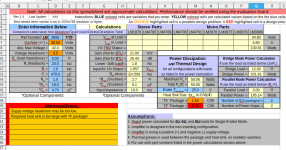
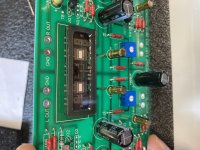
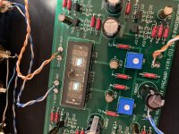
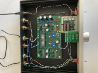
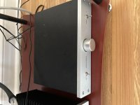
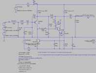
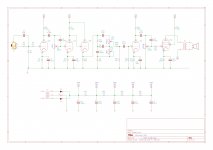
Anyways, playing around with somewhat typical Class AB amplifier.
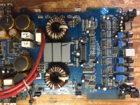
This is a design of mine below.
I just found using common high quality transistors.
Using Feedback current sources.
Then Basically keeping the second gain stage simple eliminates rail stick.
And Using a basic current mirror and boosting up the LTP current higher
than usual. Around 6ma
Seems to hold up rather well for distortion.

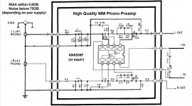
R3 and C2 seem to be the real magic,
this network seems to make the
amplifier rather stable, and allows C7 to remain rather low. Which seems
to defy a majority of possible THD at High Frequency.

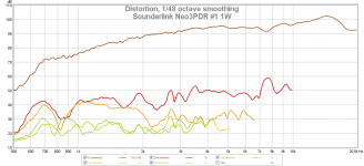
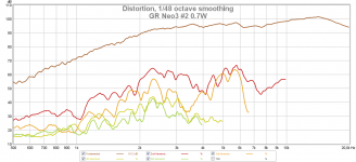
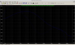
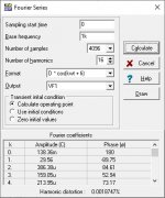
.001 % Distortion @ 1 kHz
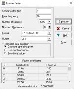
.006 % Distortion @ 20 kHz

attachment.php


attachment.php


attachment.php


attachment.php

Attachments

  • PHARAOHEXTREME3.JPG
    PHARAOHEXTREME3.JPG
    102.4 KB · Views: 998
  • P1K.jpg
    P1K.jpg
    51.4 KB · Views: 607
  • P20K.jpg
    P20K.jpg
    51.3 KB · Views: 606
  • PScopeClip.jpg
    PScopeClip.jpg
    71.6 KB · Views: 581

Discreate Class A CFA Solid State Preamp

It all started when I started researching about Current Feedback Amplifier
I found this
http://hifisonix.com/wordpress/wp-content/uploads/2017/10/CFA-Front-End.pdf
Before trying to make a full blown Class AB 100W CFA amplifier with Quasi Complimentary FET output.
I made my mind to try to make a Line Level Preamp with CFA input stage with Class A Operation.
Main purpose for me is to learn solid state Amplifier design, I am bored with OP-AMP at this point of time.


Design goals[More like Wish list]:-
*10Vpp Swing without Clipping with Dual 18V supply.
*Complete Class A Operation
*Zero Global Negative Feedback [Local Compensation is necessary]
*Harmonic Profile Shall be Dominated by H2
*H3 shall be close to H2 to add necessary psycho acoustic feel of detail.
*Anything higher than H4 shall be below -120db [As H5 and Higher are responsible for listening fatigue]
*Higher order than H2 shall descent monotonically and H2 increases with increase in Frequency
*Close to 200V/us Slew rate
*Higher than 400Khz bandwidth

Use Cases:
*Line Pre Amplifier
*Headphone Amplifier for Inefficient Planer Headphone
AMP-Concept.png


I hope all of you will help me in my journey to make some Solid state amp

🙂

Attachments

Weird valve amp oscillation

Hi everyone, I have a valve guitar amp ( 5E5A schematic) that I have been using since 2005, it has recently had all its electrolytic caps replaced, it has a strange oscillation when I turn up either volume knob, it's really faint, untill I plug a guitar lead in then it's a loud noise, its a fast oscillation sounds like a cat purring, was wondering if anyone has come across this before?

multiphase class D

I've been thinking about releasing this idea into the wild to see what happens for quite some time now. I tried to get away from the ring oscillator method of spacing the phases, but haven't come up with anything that works comparatively well let alone elegantly.

There are some known problems.

Current sharing in the real world. In spice everything is intrinsically matched, so this problem goes missing there, although purposefully drifting various values has some interesting effects. For one thing there usually has to be at least the minutest obvious difference between phase legs or all of them tend to stay marching along together as if it were one big parallel inverting leg and complete waste of redundant circuitry.

The funny diode clamp at the comparator input is responsible for the "carrier-less" frequency locking. However, there is an irritating limitations with it that is kind of hard to explain because I don't even fully understand how it works when it does. But if you play with this thing long enough you soon notice that the opposed pair of coupled trapezoids coming off the capacitively loaded clamp end up getting compared against the long ends instead of the short ends. The result it that instead of slopes that run linear all the way up to 0/100 of duty cycle, they come apart and the phases let go of each other as the whole oscillator plan blows up, until the input signal drops down to the point where comparator inputs cross again at regular intervals. Whoever comes up with a way to get something like this to run all the way up to 100% duty cycle while keeping all the legs locked together and balanced, gets the prize.

Oh yeah, and in reality you need a handful of isolated gate drive supplies. 🙂

I have built a single phase version of this with a nifty little resonant gate supply and regular silicon FET output. If you take the clamp stuff away it basically turns into a Putzeys amplifier. Even one phase gets to be a lot of tiny transformer windings. For the pulse transformer I ripped the base drive core out of a bunch of old CFLs. For the comparator I used a AD790. I tried a real build with LT1711 on a ground plane board and it oscillated to beat the band. I mean that thing would not stop talking to itself. I might have been able to tame it but went another way. I doubted it would be better than the 790 in this application anyway.

If someone did this already, especially if simpler or better, let me know. EPC models are big and clunky. To run this you'll need them EPC Device Models

Attachments

Custom Preamp / Small Amp Enclosure

Unable to source a preamp chassis that I liked, I decided to design and fabricate my own.

Attached are photos of a preamp build using a Broskie Aikido™ line stage, Erhard Audio phono and power supply boards, and an inexpensive relay-switched input PCB.

The PCBs are mounted on a sub-plate that can be raised with stand-offs, which allows for through hole and point-to-point builds.

Attachments

  • Front view with cover.jpg
    Front view with cover.jpg
    73.4 KB · Views: 329
  • Rear Panel Open.jpg
    Rear Panel Open.jpg
    99.5 KB · Views: 320
  • side angle view.jpg
    side angle view.jpg
    86.9 KB · Views: 332
  • Front View Open.jpg
    Front View Open.jpg
    98.4 KB · Views: 329
  • Inside View.jpg
    Inside View.jpg
    220.2 KB · Views: 321

DIY 2 Way With 4" Woofer Needed

I recently picked up these powered BT speakers from Amazon, model R28BTUS. They sport a 1” tweeter and 4” woofer. Didn’t need them, but for $25 what was I to do? Crossover is a 2.2uF cap on the tweeter. Drivers wired in series. They aren’t too bad with the ports stuffed, but they very likely can be improved.

The Overnight Sensations using the HIVI T20-8 and B4N design appears to be a very good fit to the unit’s .18cf (5.2L) cabinet. The OD of the B4N frame is .1” larger than the existing, might be able to sand out the difference. The hole for the tweeter will need a bit of enlargement, but that should be easy. Even the odd port looks pretty close to what is needed. Driver costs would be $23 per side, about as low as can be expected. I have good stash of crossover components, so I’m not that concerned about crossover cost.

Are there any other 2 way designs out there that use similarly sized (or somewhat smaller) drivers in about a 5L box that I should look at? Is there a full range driver that might fit with no modifications? The drivers can’t be surface mounted, the grill is flush to the front baffle and there would be no room.

Attachments

  • SPK DIMENSIONS.jpg
    SPK DIMENSIONS.jpg
    320.5 KB · Views: 1,012
  • R28BTUS.jpg
    R28BTUS.jpg
    305.6 KB · Views: 566
  • Overnight Sensations.jpg
    Overnight Sensations.jpg
    221.9 KB · Views: 544

How to build the F5

...Well, this thread will be how I build mine. 🙂

Nothing out of the ordinary, Peter Daniel boards, single transformer, Tech-DIY transistors and other bits, HiFi2000 chassis.

I have collected all the pieces and finally today the chassis arrived from Italy! I am ready to start!

DSCF3561.jpg


DSCF3564.jpg

Here is the obligatory "armory" photo. Only one of the amp channels shown.

DSCF3567.jpg

The rear panel. I thought I ordered an Inlet Module with a switch, but I didn't read the datasheet well enough, and it has a neon light power indicator instead. Oh well. Luckily I have a couple of nice bat-handeled switches, I will use one here. The Jacks and RCAs are also from my box, I think they are Vampire.

DSCF3565.jpg

Here are the contents of the Tech-DIY F5 kits, the Peter Daniel's boards, and a couple of silpads. I also have micas and grease, I will most likely use those.

DSCF3566.jpg

The PSU components. Vishay rectifier blocks, Peter Daniel PSU board, resistors, 33,000uf capacitors, CL-60 thermistors, and a big-honkin' 600VA transformer.

When I was determining the transformer size necessary I must have had a brain-sneeze, I must have only thought of one secondary! 😀 Oh well, it was only $20 more than the 'proper' (400VA) size. The 4-pin caps will work on the board with just a bit of modification.

DSCF3562.jpg

If you were wondering, the Peter Daniel boards are very small. Also very nice!

That's it for now, I will post more photos as I progress.

Amplifier for 14 ohms headphones

Hi all,

I’m after recommendations on diy headphone amplifiers for a nice old pair of Sony headphones I’ve unearthed that seem to be very low impedance, at 14 ohms.

I have a nice case, in the size and style of a quad 405/34 stack it will sit on, some nice neutrik socketry, a 20va 18-0-18 transformer and the bits for a power supply.

I have read around the topic and have been convinced that class A is the way forward at these power levels.

The headphones themselves are rated at 1000mW, which at 14 ohms and 102dB/mW sensitivity would be deafeningly loud. Never the less I have calculated this to be about 10v pk-pk and 300mA output is needed ( to allow some margin).

I would be grateful for suggestions as to designs, so far I am liking the idea of knocking the three transistor amplifier on this forum together but would be interested in more powerful projects to build and try to compare.

Kenwood KD series t/ts repairs, advice needed

I've been using Kenwood KD series decks for over 15 years. I decided to change all the electros on the first deck that I thought was the problem for non-functioning - it wasn't and now the second deck has ceased to function.

Both the bearing systems are fine as are both the TX since the power reaches the PCBs.

I will now have to do continuity checks on both and I do have a site that bought up a lot of Kenwood's KD components but if I cannot fix the problems does anyone know an experienced repairer who can help.

I live in France, so I need at least an EU source that can help - thanks in advance.

  • Poll Poll
EBS3 what was your experience? (Lavoce 12" tuning)

Does EBS (extended bass shelf) give good results?

  • Yes, go for it!

    Votes: 2 100.0%
  • No, Not worth it in this case.

    Votes: 0 0.0%

I am building a 2 way with a Lavoce 12 WAN123.00 woofer. I am considering a ebs3 alignment. This will lower the f3 from 64hz to 50hz. I am wondering what other peoples experiences have been with a similar situation. I guess that I will have to pull the 3db down above this shelf like it is part of the baffle step. I would like to be able to use this without adding a sub to make it sound okay.

Thoughts?

How much to spend on DSP

Hi there,

I'm in the process of sorting out all the parts to make a class D plate amplifier.

I'm looking into buying a DSP board so that I can bi-amp rather than using a passive crossover.

I've seen a few options around-

-MiniDSP
-Dayton audio
-Sure electronics

The miniDSP option is about €100, which is a bit pricey as that's about the same as I will be spending on amplifier modules. Then there's a massive gap down to the Dayton and sure boards at about €20-30.


Does anyone know about the relative strengths of these products? It's there a significant difference in the quality of the signal coming from a MiniDSP unit?

And most importantly, does anyone know of any OEM manufacturers who make reasonably priced boards?


Thanks
Peter

SPDIF out of TV low level (once D to A'd)

I have a 9th generation Pioneer Plasma and if I use the Optical SPDIF out, to any DAC the resulting analogue signal is very low.
If listening to music content it fills my room but, a little more, if watching a concert for example would be great.

When I was fixing TV's for a living, the Digital out always, no matter what Manufacturer, seemed low to me.

I was thinking of using a cheap DAC chip, using an OP Amp to raise the analogue level to say a good 2V rms and then A to D-ing the signal using a circuit similar to what must be available at the O/P of the average Minidisc unit.

Thoughts and any other possible solutions greatfully received.

P.

Schematic for REL T-3 (and a few other questions)

Anyone have a schematic for the amp i an REL T-3 subwoofer?

My T-3 is blowing fuses. I'm pretty sure the output transistors are shorted. The appear that way when measure in the circuit. I'll pull them today and retest.

In tracing the circuit, it does not appear that there is any voltage regulation for the output transistors. Current flows from the transformer to the PS caps and then to the transistors.


I can't find any VR ICs on the board, though there is one op-amp that could be in a part of a VR circuit.


Is it comment for outputs to be driven from an unregulated source?

Finally, assuming the transistors are bad and a replace all 4 (2 NPN, 2 PNP), are there any guidelines for setting the idle current if I don't have a schematic or manual? Should I just leave it as is in that case?


thanks,


James

Overture design guide issues with heatsink and voltage

Hi friends,

I've got my LM3886 stereo system running now for a test and I re-checked the Overture Design Guide spreadsheet after double-checking the supply voltages.

I'm not sure if I should be worried about the supply voltage being +- 38.5V, which leaves 3.5V headroom. Should I be going for a smaller output voltage on the secondaries on the transformer (currently 25V)?

It also seems to think that the heatsink is going to cause me trouble. I've felt the heatsink and it feels lukewarm after 30 minutes of listening. Does this mean the design doc is wrong or I am not outputting 100W ?

I've filled in my values in the spreadsheet and attached the screenshot below.


EDIT: I've got thermal paste on one chip (the other will be done in the next few days), and no insulation washers. I've got the TF package, the one without the metal tab on the body.

Attachments

  • Screenshot_20210810_165300.png
    Screenshot_20210810_165300.png
    155.1 KB · Views: 271

Please Help me identify these speakers

Hi there folks I recently bought these old speakers ,they seem to be coaxial speakers .I have spent 3 days on the internet trying to find out what brand of speaker they are without any luck so i can repair the high frequency drivers in them .The high frequency drivers are very small compression drivers with 25mm phenolic diaphragms ..the person i bought them from says they were built around 1965ish..if you can identify them please let me know so i can save these speakers...thanks in advance folks
Ill add the photos as soon as i can work out how to upload them here

LC & LCL DC Filament Supply: The Choosing of the Choke

Evening all,

I've been embarking on more elaborate power supply designs, while going through Thomas Mayer's blog bit by bit. I'm wanting to include in my next build a choke input filament supply such as these examples, from his blog:


76aDhDr.jpeg


J1kCuwU.jpeg


So I'm shopping up the components that aren't just on the shelf, and that means just the high current chokes... I won't be using 220, and it will be 5v from the transformer to 2.5v filaments @3amps for two 45 tubes.

The questions I have are:
1. What is the motivation to use a high-quality choke in this position, eg a $150 Lundahl? Why would I not use an $8 toroidal from mouser with the same inductance and current ratings? Is wire gauge important? Why wouldn't we all just go out back to that dead washing machine in our yards, pull the motor and unravel the wire, fetch a nice stick from the woods and wrap ourselves up the medieval clay-pot battery-accessory of an inductor that we all can have for free?

2. Will precise inductance matter much at all in this position? As long as DCR is right, am I correct that I can use a wide range - and would it be correct that I can go ahead and stick to the low end of that range, to minimize size without impacting the function? Say, 1 to 10 mHy?

Thank you in advance for any information. Links are quality input in my book.

Modifying 100 watt LXI amplifier circuit

Hello every one, I would consider this my second major solid state amplifier project, but with this one it will be like rebuilding an entirely new amplifier, so I am making an attempt to make the best one I can from what I've salvaged from this one and whatever else I can find in my junk piles.

The amplifier is made by Sears (go figures, considering there is no info what so ever about it). It produces 100 watts into 8 ohms and consider how cheaply made it is, it sounds really good and is a well designed amplifier. I even took the time out to draw up a schematic, which can be used for the convenience and personal use of others.

I have many ideas in mind of how to modify the circuit for improvements, but only understand the basics, so I am looking for ideas of what would make this circuit better, more current capable and efficient.

I have made a few posts on the Class "A" Hybrid Amplifier thread but have not had much help there since this is a class "AB" amplifier, that I indeed want to turn into a Hybrid of some sort, mainly to get rid of the obsolete chip fet at the input stage of the amplifier, so I am more than willing to be walked through the modifying process, as I now have all SUMMER!!! 😀

Here is the original schematic that I drew up, if there are any reasons why what I drew up may not work please let me know! I will correct it as necessary. 🙄

Attachments

  • lxi amplifier(small).jpg
    lxi amplifier(small).jpg
    66.9 KB · Views: 980

FS: 7 & 9 Pin Tube Socket Extenders/Adapters

I'm offering a set of (1) GC #9243 standard 7 pin and (1) GC #9244 standard 9 pin tube extenders, each labeled "TV tuner socket adaptor." Both are about 2 3/8 inches high. Other than a bit of tarnish on some socket pins and test terminals, these are in nice shape and are tested & working.

$28 for both, free First Class USA shipping included. PayPal only.

Attachments

  • upper_view.jpg
    upper_view.jpg
    406.7 KB · Views: 97
  • lower_view.jpg
    lower_view.jpg
    316 KB · Views: 94

Yamaha CA-610MKII Restoration/upgrade

I'm looking to renew my Yamaha CA-610MKII. I've had it since 1996.
It is from 1977 I think and is all original and works.
Looking at the Schematic, none of the transistors are available unless you go on ebay. I don't have a problem replacing capacitors as they are available.

I found this website that someone named S.Kinder renewed one but left out cross-reference parts he used!

Vintage Hi-Fi Audio Restorations: S.Kinder's Yamaha CA-610 MKII Integrated Amplifier Restoration

I like what he did and there are a few transistors in the pics and reading that show what he used and are available from mouser/digikey.

So I made a list of part numbers and the substitutes that I think will work. Took me all day!

I'm asking for help if anyone could verify my selections are good and if not, please let me know of alternatives.

I really want get this unit a little more current as far as parts.
For the cost of the replacement semi's, I think it's worth it.

Please let me know, any help would be good...

Thanks all

Attachments

  • Screen Shot 2019-02-22 at 10.21.11.png
    Screen Shot 2019-02-22 at 10.21.11.png
    588 KB · Views: 365
  • Parts.jpg
    Parts.jpg
    148.5 KB · Views: 310
  • ca610_ii.pdf
    ca610_ii.pdf
    2.3 MB · Views: 163
  • Parts.txt
    Parts.txt
    772 bytes · Views: 150

What is going on with the price of valves!?

I'm a casual observer of valves on eBay, just noticed this £1500 (2000 USD) auction. Maybe I don't have the nose for a bargain but just seems like a load of TV/radio valves. Could not see any of the crazy price audio things. Well I suppose it's £1 per valve. So not bad value. I just surprised someone would pay so much and need so many!


Very Large Collection of Old Radio Valves | eBay

Attachments

  • Screenshot_20210822-191631.png
    Screenshot_20210822-191631.png
    752.8 KB · Views: 813

DML as surrounds for atmos theater?

Greetings from an interested newbie to the DIY speaker realm.

I am going to be building a sub set up to sort of match some furniture.

The rears don't have many good options as far as a match goes but if a DML could serve well as a rear surround I have some decent options. The ceiling speakers can be worked around in a few ways but DML might be pretty interesting for that application as well.

Sorry if this has been previously addressed I looked around a lot and used the search function however I didn't find any discussions on it.

Is this a stupid idea because the surround effects are supposed to be lower and DML's are going to be too "loud" when driven by the decoding Amp?

My limited general understandings would be the DML have little bass response below 150htz is that a concern with surrounds? My experience is pretty limited and involved pretty crappy surround speakers in the past. Some Polk cubes that honestly never really sounded much better than an 8 dollar RadioShack 9 volt transistor radio.

Thanks for any feedback.

Questions related to using Cadsoft Eagle-help available

Hi all,
I want to start this thread to answer questions related to using cadsoft eagle effectively. I have been using eagle for over 2 years now and done many layouts of single sided and two sided ones. Although sprint is preferred by many to make simple analog layouts, I prefer eagle because of its compatibility with schematic.
All you need is a carefully checked schematic and correct devices, voila you are guaranteed to have correct layout.
I dont say i have mastered eagle, but i would say i am about 60% proficient.

I still have no capability with making ulp's. never felt the need to, as there are many many ulp's available on internet that get the job done.

This is not going to be a tutorial thread, just question and answer thread.
and would cover questions related to the following topics
1. making sch
2. cloning an sch
3. making packages, symbols and devices
4. making layouts
5. Cloning layouts
6. importing gerbers for cloning
7. DRC for home etching and for manufacturing
8. generating BoM
9. Generating gerbers
10. Generating pdf's (positive images and negative images of solder masks and copper layers), mirroring them, etc
10. any other

In the process of answering questions, this thread hopefully will also lead to make me more proficient in eagle and help in finding something new which I hadnt used before.

Thanks and regards

Prasi

Korg B1 + S11 Regulated PSU

Hello,

I have a Korg B1 + S11 Regulated PSU for sale.

Korg B1 with best parts: Nichicon, Takman, Black Gates NX, TKD Poti, Elma Switch, Cardas RCA Connectors.

The S11 PSU is in my opinion the best option for the Korg B1.

The aluminum front plates are powder coated.

The price for both is 400,- € ‚ plus shipping.
I can unsolder the 6 Black Gates NX and reduce the price to 300,- €, plus shipping.


Kind regards

Andreas

2SK76 2SJ26

Hey guys, I need a favor if someone is willing. I have these parts and I think they are suspect, I got them some time ago from a vendor I have had luck with in the past, but I have limited curve tracing available to me. I have a total of 8 parts that I'd like to get tested.

I would be happy to pay if someone has a curve tracer capable of checking them out and matching.

PM me if you are willing and we can discuss the parts and payment.

Thanks

JT

Dayton PC83-8 (3") test results

I picked up a couple of these new Dayton 3 inch poly full ranges Dayton Audio PC83-8 3" Full-Range Poly Cone Driver for testing. I thought I share the results here as they were designed as a full range.

I was curious about using them as a midrange, the spec sheet indicated they should have a wide dispersion up to around 4KHz. They'll also do double duty as a test speaker an active cross over project.

The tests are geared towards off axis performance, distortion, and I did EQ them and listened for a while. The cobbled up enclosures will be sufficient for that purpose.

Index to trials:
1) Box 8L - Dayton PC83-8 (3") test results
2) Cylinder 4L - Dayton PC83-8 (3") test results
3) Box 8L + large baffle - Dayton PC83-8 (3") test results
4) MLTL - Dayton PC83-8 (3") test results
5) Omni opposed drivers - Dayton PC83-8 (3") test results
6) Le Cléac'h 7-Petal Horn - Dayton PC83-8 (3") test results
7) Le Cléac'h 11-Petal Horn - Dayton PC83-8 (3") test results
8) Fixing the Le Cléac'h Petal Horns - Dayton PC83-8 (3") test results
9) BP8 'subwoofer' to get some LF performance Dayton PC83-8 (3") test results
10 ) Bass Reflex - Dayton PC83-8 (3") test results
11 ) Tractrix Rectangular Horn - Dayton PC83-8 (3") test results

Bleeding resistor + led

Hi,

I'm building a phono tube preamp from Valvewizard:

The Valve Wizard

With this power supply:

The Valve Wizard

I'm using the last schematic, without the voltage doubler. But I've notice that the 100k 2w resistor it's getting very hot.

My B+ voltage is 350V

And I use a switch with 12V led:

Aluminium Switch with Blue Light Circle 2NO2NC 250V 5A O19mm Black - Audiophonics

So, If my math's are right. I need a 33k 5w resistor?

Thanks.

Pioneer FX-88-ZI Tuner

This Tuner is an integral part of my Mum's system.
It has stopped responding to most of the buttons.
Free download pioneer fx 88 zl service manual
From the schematic, the buttons, all tactile switches not capacitive, all connect to the micro-controller.
I suspect the limit of my ability will be to ensure the mcu is receiving +5V.
Is there anything else I can possibly test for?

When on a station it appears to work perfectly.
Projects by fanatics, for fanatics
Get answers and advice for everyone wanting to learn the art of audio.
Join the Community
507,624
Members
7,880,654
Messages

Filter

Forum Statistics

Threads
405,890
Messages
7,880,654
Members
507,624
Latest member
Neilonpoint