SSHV2-P.C.Bee V4 Mosfets-ES9018K2M DAC-LT3042 DIYINHK-PSU+3/5/7V- Controller ES9018K2

SSHV2-P.C.Bee V4 Mosfets-ES9018K2M DAC-LT3042 DIYINHK-PSU+3/5/7V-Controller ES9018K2M

1. Pee Cee Bee V4 Two board plus 4 selected Mosfet 2x ECX10P20 2x ECX10N20 55 euro plus ship..SOLD
2. ES9018K2M DAC Isolated with ELNA Audio Cerafine 100uf/10V made in Japan with LM opamp. 30 euro plus ship..
3.0.8uV Ultralow noise DAC power supply regulator +3/5/V, 1.A LT3042 DIYINHK 35 euro plus ship.. Sold
4. PSU type D Reflector +3/5/7V 4ΧMUR 860, Μain Cap 10.000uf/35V Panasonic , Panasonic 1000uf/25V Low ESR, WIMA 0.22 uf MKP 35 euro plus ship..
5. Controller for ES9018K2M DAC 45 euro plus ship...
6. Salas SSHV2 with XTP08N100D2 IXYS SOLD

Attachments

  • SSHV2.jpg
    SSHV2.jpg
    98.2 KB · Views: 1,203
  • IMGP0027.jpg
    IMGP0027.jpg
    988.6 KB · Views: 1,137
  • IMGP0028.jpg
    IMGP0028.jpg
    981.5 KB · Views: 1,115
  • IMGP0029.jpg
    IMGP0029.jpg
    987.1 KB · Views: 1,073
  • IMGP0030.jpg
    IMGP0030.jpg
    815 KB · Views: 1,048
  • IMGP0031.jpg
    IMGP0031.jpg
    1,012.5 KB · Views: 478
  • IMGP0034.jpg
    IMGP0034.jpg
    922.6 KB · Views: 445
  • IMGP0043.jpg
    IMGP0043.jpg
    545 KB · Views: 370

L12 120w amplifier kit on eBay....anyone familiar with it?

2pcs L12-2 120W+120W power amplifier kit | eBay

The above link caught my attention a while back...mostly due to the fact I have a toroidal tansformer that will mate with it and enough PRP resistors and Black Gate caps along with other high end replacement parts i can tweak it with.

Just wondering if anyoneis familiar with it or could comment on the circuit shown in the ad....is this a quality design? Think its worth $35 to give it a try?

Thanks!

New Dayton MX "Max-X High Excursion DVC Subwoofer" line

There is a new subwoofer line available at parts-express, called the MX "Max-X High Excursion DVC Subwoofer". It is available in a 10, 12, and 15 inch models and costs less than the equivalent Ultimax. Excursion is listed - somewhat confusingly - both as a Klippel verified 70% BL rating (called 'XBL', no relation to XBL2 motors) and a mathematical (lower) Xmax. I think it came out on April 15, 2020, though I never saw any marketing for it.

Notes from AVSForum:
"If this is indeed them finally releasing the HE series they teased a few years ago then there isn’t an 18. It was planned but never materialized."
"I'd say it's more about trade-offs than one being better than the other. For sealed, I'd lean towards the UM and for ported towards the MX."

Marketing Blurb for the 10:
The Max-X MX10-22 10" dual voice coil high excursion subwoofer from Dayton Audio is built for incredible low frequency extension and high SPL. This affordable driver combines durability, efficiency, and maximum displacement into a great looking speaker that will deliver the deepest bass with power and authority. Optimized for use in compact enclosures this driver is ideal for home subwoofer designs and high impact car audio systems.

Key Features

±13.7 mm Klippel verified excursion and maximized surface area for excellent displacement capability
Seamless dish cone is extremely rigid and durable with a sleek and modern look
Custom tooled surround allows long throw while maximizing cone surface area
Extensive venting cools the voice coil enabling high power handling with low power compression
Dual spiders maintain linear excursion for lower distortion even when pushed to the limit
The dual 2 ohm voice coils give you the ability to get the most out of any amplifier

Links:

Dayton Audio MX10-22 10" Max-X High Excursion DVC Subwoofer 2 Ohms Per Coil

Dayton Audio MX12-22 12" Max-X High Excursion DVC Subwoofer 2 Ohms Per Coil

Dayton Audio MX15-22 15" Max-X High Excursion DVC Subwoofer 2 Ohms Per Coil

Tubelab SSE troubleshooting

Hi all,


I've been the happy listener to a Tubelab SSE that I built some 3 odd years ago. Just a few days ago I turned it on and now the volume output is drastically lower. I used to be able to listen to things at 50% volume but know I have to turn the knob up to almost max to get it back to where it was. I've replaced all of the tubes already and it hasn't solved the issue. Does anyone have any troubleshooting tips that I can use to identify the source of this problem?


I'm not an expert at electronics and was only able to build the SSE because the instructions were clear. I do have a multimeter and a general knowledge of electrical safety though.

Tube Amp Power Transformer

For sale is a power transformer for a tube amplifier. It's chassis mount so it takes a bit of work with a nibbler for it to fit on the top plate. The upside is that it transfers heat to the chassis better.

It has cloth leads in good shape and I put on some new 10-24 nuts so you won't have to hunt those down. I can get the primary and secondary DCR in the next couple of days so someone could model it in Duncan Amps PSUD II

It's quite beefy I'd estimate it at around 6.5 lbs. The laminate stack is very thick and should work great for a 50 watt Push-Pull EL34 amp as an example. It has both 12.6 and 6.3 volt windings so you could run some 12AU7s in the signal and phase inversion sections and 6.3 for the output tubes and use the 5 volt for the rectifier if so desired. If you go with solid state diodes you'll only need two for full wave rectification so you can splurge on expensive ones and should be able to push over 400 volts for your B+ (probably 25 volts or so lower with tube rectification).

Tested at 123.1 AC line voltage at my residence I measured the following voltages with the related colored wires with the transformer unloaded. The higher filament voltages are due to the higher AC input than typical and being unloaded.

Black-Black: AC in (123.1 volts)
Red-Red/Yellow-Red: 373-0-373 volts (746 Center tapped)
Green-Green:14.46 volts
Brown-Brown: 7.22 volts
Yellow-Yellow: 5.41 volts

This should handle a quad of EL34 on the filaments. Four to five 12AUX tubes, and 3 amp rectifier tubes like a 5U4GB and at least 250 ma on the HV.

Price is $50 plus $18 shipped to the lower 48 via a USPS medium flat rate box. Sorry, shipping only to the US.

Attachments

  • DSCF6158.JPG
    DSCF6158.JPG
    450.6 KB · Views: 120
  • DSCF6159.JPG
    DSCF6159.JPG
    453.3 KB · Views: 124
  • DSCF6160.JPG
    DSCF6160.JPG
    458.6 KB · Views: 113

Tube hybrid CC/CV bench power supply with preregulator.

I designed this power supply using two EL36 pass tubes, and a thyristor pre-regulator. This supply should give constant current and constant voltage capability at relatively low cost.

The thyristor chopper/pre regulator should keep the voltage over the triode mode EL36 at about 100V. EL36 cathode current is in excess of 220mA continuous, so it is possible to make a 200mA supply with a single tube.

The control is just a simple cascode of two LM317AHVT to give CC/CV capability.

Please tell me what you think, i have the PCB nearly done.


Tenative specs are 1.25-400V out with TYN812 thyristors and a 400VAC 500mA transformer for 250mA DC out.

Attachments

  • board.png
    board.png
    176.7 KB · Views: 178
  • Schematic.jpg
    Schematic.jpg
    525.8 KB · Views: 174

Sony V-FET Amp 5650 - excellent FS

I have too many V-FET amps and so letting this one go - Sony TA-5650, - not modified. It works fine and I adjusted the Bias / works beautifully.

Prefer US buyer - contact me for details / price shipping payment. If some one in the Austin TX area , you can pick it up

Attachments

  • DSC02683A.jpg
    DSC02683A.jpg
    1 MB · Views: 430
  • DSC02674.jpg
    DSC02674.jpg
    1,021.9 KB · Views: 424
  • DSC02679A.jpg
    DSC02679A.jpg
    1,019.9 KB · Views: 413

wooohooo! Three Rowe AMI amps for $200NZD!

At last! For the past four years I've been reading stories about dumpster finds, thrift store bargains etc etc from you lot - now I got mine!

Anyone got any info on these? Supposedly from Rowe AMI Model L jukeboxes, they appear to be stereo, I suspect 12a*7 drives EL84... Pretty excited to get these babies home and have a play!

Attachments

  • roweami amps.jpg
    roweami amps.jpg
    78.3 KB · Views: 463

1:2 stepup input transformer, tube amp.

Recommendations please for a really transparent 1:2 stepup transformer for a 2-stage 300b/2a3 amp. Input tube would be typically one with a mu of around 20 like ECC99, EL33 or EL84 in triode etc.

In my case please include input transformers available in the UK/Europe. However it's also possible to order from the USA or elsewhere and factor in the import/shipping cost, so all possibilities are on the table. Obvious examples would be:

Sowter
Lundahl
OEP
Slagle
Hammond broadcast range
Jensen
Cinemag
Other......

I'd be particularly interested in discussions of core material, e.g. amorphous, nickel, finemet etc. and which is best for transparency and clarity.

Recapping crossover, odd value series combinations?

Hi there,


I'm thinking of recapping my Mordaunt-Short MS35Ti with new caps.


The originals are 4uF for the tweeter, and 7uF for the woofer.


I can't find direct replacement 4uF caps for the tweeters. The closest I can get to is to put 12uF and 6uF Alcap Low Loss non-polarised electrolytic in series. That should get me 4uF.


Is there any issue with putting different value caps in series for the crossover? Will it mess with ESR or sound quality if they are odd values?


Thanks

Not DIY but I need advice

I need a new Subwoofer amp and a dinosaur is available on eBay.
Before I make an offer is the old Alesis Matica 900 generally a reliable unit and easy to repair if anything goes wrong?
Only looking because cash is very tight due to Covid.
Link to eBay item
[USA] 22kg!! Alesis matica 900 450 watts x2 power amplifier | eBay
Not paying the asking price but I made what I think is a fair offer.

Replace a surround>??

I have a pair of 15" woofers on the shelf with a disappearing folded paper surround. It seems that they have disintegrated in a very short time after putting to one side.
They are cheap drivers and not worth paying $200- to repair but a replacement foam surround is $50- for the pair.
Two questions; how difficult is it to replace a surround if I leave the spider in place and does replacing a paper surround with a foam change much?
Speakers are from Jaycar and I bought them about 20 years ago and they were worked hard in my party boxes but VC still seems OK, no scratching etc.

MTX TH-1500D

Hi,


I repair MTX amplifier and accidentally shorted the power supply of the preamplifier board during measurements with a multimeter. As a result, the diode (most likely the zener) was damaged. Its designation on the PCB is D104. The PCB designation is MVP305-C 07/02/08

There is a similar diode on the other side and it seems to me to be the same as the damaged one, but I am definitely not. It seems to me that the circuits with two IRF540N mosfets can generate + - 15 voltages for operational amplifiers. One of them has been short-circuited and now I have + 45V on the TL074C operational amplifiers. 😡


Does anyone have this amplifier or its photos in high resolution or know what kind of diode it is?I would be grateful.

Attachments

  • rsz_20210903_120754.jpg
    rsz_20210903_120754.jpg
    1.1 MB · Views: 147
  • rsz_20210903_120843.jpg
    rsz_20210903_120843.jpg
    1.1 MB · Views: 126
  • rsz_20210905_160815.jpg
    rsz_20210905_160815.jpg
    940.9 KB · Views: 130
  • rsz_120210905_182456.jpg
    rsz_120210905_182456.jpg
    1,003.5 KB · Views: 169
  • rsz_20210905_153718.jpg
    rsz_20210905_153718.jpg
    940.4 KB · Views: 113

FS: Bruno Putzey’s balanced preamp + Maya line stage PCBs

For sale is:

two unassembled PCBs: the Bruno putzeys balanced preamp plus the Hans Polak input extension/relay board PCBs

One Hans Polak input PCB with smd components premounted

Two Hypex regulators [note: these are being retained and are no longer part of the sale]

One Vicol audio/Maya advanced R-2R preamp kit for use with the aforementioned boards. It is an OLED screen and has BT ability.

None of these boards have been used; they are as they were when I received them. Assembly instructions and BOMs are not provided. I never assembled this and have subsequently went another route.

Make me a offer, plus PayPal fees plus shipping. Ships from 94609.

Attachments

  • 7632AD12-91DC-4827-91E6-4E5C61732CC0.jpg
    7632AD12-91DC-4827-91E6-4E5C61732CC0.jpg
    1.1 MB · Views: 471
  • 1F1A6216-7A5E-4CA6-85D4-C750D87994DF.jpg
    1F1A6216-7A5E-4CA6-85D4-C750D87994DF.jpg
    1.1 MB · Views: 452
  • 8DDDCA27-334F-4FA6-9750-FA999745E558.jpg
    8DDDCA27-334F-4FA6-9750-FA999745E558.jpg
    720.8 KB · Views: 438

WAW dipole

Hello,

I need some help before starting my new project. I intend to make a woofer assisted full range dipole, using one 4.5 inch full range and two 12 inch woofers (per speaker)

Full range driver that would be used:
https://www.sonido.hu/adat_pdf/sfr-145a.pdf

Low frequency drivers to be used:
SB Acoustics SB34NRX75-16 12" Woofer, 16 ohm

The idea is to make a semi-passive dipole. I would like to add a first order crossover, since it's the simplest and offers phase coherence. All drivers would be fed the same signal from a single DA converter. Parametric equaliser would be used (whether by mini dsp, or inboard Linux tools) before DAC.

Possible baffle design would be similar to one from the link under. I have no idea how would this baffle design impact frequency response, so its open for changing.
http://www.pureaudioproject.com/cube-10-open-baffle-speakers/

I can source Sonido easily, so I'd like to build the system around it. Unsure about aforementioned SB drivers. They have pretty high inductance. How would two of those drivers' inductances affect the bass frequency and crossover? I've found cheaper drivers with less inductance, but they all tend to have high resonance frequency.
Also, since it's going to be a dipole, sonidos frequency is going to have downward slope towards lower frequency. I'm not sure how much of an overlap between the 4.5 inch and 12 inch drivers there would be and if a first order crossover would be usable. Maybe with some equalisation afterwards?

I'd really like that first order crossover, since a in-phase frequency response is a general idea behind this project. Other than that, the simpler, the better.

Thanks ahead.

Stefan

Flip terminals on audio receiver need repair/clean of debris

Hello,

My usual forum for anything DIY Audio is at Full Range speakers. But I have an issue with a Yamaha RPU100. These are very old USB 1 units of which I have both as a new purchase and one from Ebay.

The unit in question has given full performance on and then off for no reason after sitting unused for years due to other setups.

I've had the case off to inspect for any damage. These units have been lightly and carefully used.

For all that I can only diagnose the problem as being outside the case at the
speaker flip terminals (the red and black sort.) and that something, some wire fragment from the twisted bare leads, is shorting out the audio. Just reassembling everything may get it going. But if moved, things go dead again.
The flip terminals are not easily removed as in other older audio where something unscrews and you change the part. These flip terminals go to
a fine wire block that is soldered onto a tiny 'daughter board" inside the case.

There's nothing visibly damaged to repair if I were good enough to do that.

That leaves the outside and anything I can use to clean out the cavity of the flip terminals. Compressed air with a fine tube nozzle will just move whatever it is around.

Other things I thought of: Are there any fine pin jacks that can be used instead of bare twisted wire? Or is that even acceptible?

The other last resort I thought of was to cut into the shell of the flip terminals and then inspect and blow out what wire fragment might be in there.

If this topic has to be moved to some other subforum, apologies. I have not dealt with such questions before.

ClassDaudio power supply

I am planning to build the F6 this winter after building 2 ACA's last winter. Can anyone comment on the pros and cons of using Class D Audio's large power supply with a Antek transformer (AS-4218)
Large 60,000uF Power Supply
versus building the DIY universal power supply. Do I lose anything performance wise? Does cost look to be roughly comparable? This is my first venture into power supplies and I confess I am trying to keep it simple.

Decware ZKit1 -- Board & Electronics

I ordered a complete set of electronics to assemble a Decware Zen Triode. I have the board and all of the electronics including two substituted components that were approved by Steve Deckert. I never assembled it. Everything is new. I have Mouser and Quest part numbers. So, the painful work is done! You get the other parts and do the fun part!

$100 plus shipping.

Port unwanted noise/ resonances

Hi all.
I'm building a two way speaker.
in order to do some tests for the box volume and port tuning , i build a test enclosure.
I'm testing different volumes and tuning frequencies.

The drive i use is Dayton Audio DS135-8.
The suggested volume for this drive is ~5 liters.

during measurement of the port i notice unwanted peaks which are very high in db SPL.
They are to low to be port resonance.
I tried 2 port diameters: 35mm and 28.

Attached is an image with the test results and enclosure description.

initially i had the port on the top
Port with a length of 53mm and diameter of 28 (this was an initial guess on the ruining frequency.

You can see there are meany peaks.
I then moved the port to the back of the box and the 220Hz beak disappear.

I change to a bigger port, diameter 35mm and a length of 60mm.
no effect on the peaks.
I also increased the box volume to 9 liter instead of 5. no effect.

Can you say what is the source for these peaks? can it be fixed?
Thank you
Ran

Attachments

  • test 2.png
    test 2.png
    263.5 KB · Views: 265
  • 20200206_122055.jpg
    20200206_122055.jpg
    261.5 KB · Views: 258

Phonic mixer repair

I've got a phonic powered mixer in for repairs. The original issue was that the output was distorting. Previously two techs has been inside. I noticed that the two big filter caps C3& C4 has been changed to 6700uF and op amp IC502 has been replaced.
When I got the unit the output also was very low. After retouching some solder joints around the op amp which was previously replaced. The dropped output issue was resolved. I used my 8 ohm woofer and it seemed to work and I didn't hear any distortion. It is when I connected a 4ohm two way speaker I heard the distortion, the distortion is also specially in the HF region.
I looked for obvious culprits like bulged capacitors and dried joints and I couldn't find any. DC offset measured across speaker outputs were also very low and it settles around 1 to 2mV.
The service manual doesn't show the voltages which should be present and it doesn't give any instruction on any adjustments. I was hoping that you could share some ideas on what to look for. I am going to scope out the audio path tomorrow.
Also I would like to ask about the potentiometer API 500 what it be adjusting?
Thanks in advance.

Attachments

SEN / CEN All JFET IV Converter Evaluation Pack

I now open a GB thread for the SEN / CEN All JFET IV Converters, as published in Linear Audio Volume 2.

Some details and discussions of circuit variants can be found here :

http://www.diyaudio.com/forums/digi...-sen-evolution-minimalistic-iv-converter.html


The content of the evaluation pack can be found here :

http://www.diyaudio.com/forums/digi...on-minimalistic-iv-converter.html#post2688677

Each will cost 50 Euros including registered air mail but excluding Paypal fees.
Delivery is FOB, i.e. we are not responsible for postal losses.

To make life easier to source P-JFETs, I shall make available 40 pairs of 2SJ74BLs, matched to better than 30uA Idss.
These can however only be purchased in combination with the evaluation kit, and limited to one pair per person.
The additional cost will be 5 Euros plus Paypal fees.

I shall leave this open till end of September.
Minimum subscription is 60 packs, before we can start lot production.

You can subscribe by putting down your details in the following list.


Patrick

.

6-7" midbass suggestions 90-91dB/W @ 6-8 ohms

I'm looking for a pair of nice 6 - 7 inch midbass drivers with 90 - 91 dB/2.83V @ 6 - 8 ohms. Budget available is up to $300 per driver.

This is for a high end 4 way system and needs to cover roughly 300 -1000 Hz and should handle a good amount of power (and enough xmax) to allow for higher than average output levels at lower THD. Drivers with smaller voice coils (less than 38mm) won't work for me here due to excess power compression. Yes, I'm probably asking for alot here.

Most of the more common Seas, Scan Speak, Vifa drivers either don't have the sensitivity or power handling. Considered some pro audio drivers as well, but the ones I looked at don't have a track record (ie. distortion measurments, etc). Availability is also a problem here in the US for some of the more boutique type drivers.

Any info would be appreciated.

NAD power envelope

NAD made 2 amplifiers that looked identical, the 3130 and the 3240PE


from the outside they look identical but inside a very different story.


which part of the circuit would be the 'PE' bit, or is it just the entire make up of the circuit?

the 3240PE has alot of transistors in comparison to the 3130.


It would just be good to know as i will be working on a few amps going forward with the 'PE', and they look quite complicated.:yes:


The attachments have been scanned from my original manuals ,are realy good quality and may help others who have poor quality ones


many thanks 🙂

Attachments

EPIQUE by Dayton Audio

..new pricey range:

http://www.daytonaudio.com/index.php/epique-by-dayton-audio/epique-drivers.html/

8":

Epique E220CF-8 8" Carbon Fiber Cone Neodymium Driver 8 Ohm

https://www.parts-express.com/pedocs/specs/295-634--epique-e220cf-8-spec-sheet.pdf

5.25":

Epique E160CF-8 5-1/4" Carbon Fiber Cone Neodymium Driver 8 Ohm

https://www.parts-express.com/pedocs/specs/295-630--e160cf-8-specs.pdf


..While the smaller driver doesn't interest me much, the larger 8" is interesting: with decent efficiency and a lower fs than is typical for the Sd. A limitation is excursion.

For those with deep pockets, the Morel Supreme TSCM634 mid might "pair" very well with 2 of those 8"s.

Need help with AMC CD8 cd player

I have one of these and it's a very nice player, but has a problem. If anyone is familiar with the transport part of it, I would appreciate any help.

About half of the time, it fails to spin up the disc. You put the disc in, drawer closes, then it doesn't spin up. After a few seconds, it opens the drawer and the display reads "open". I've operated it with the cover off and tapping on the transport sometimes makes it work. Not always. Other times it works by itself with no help. Clearly some type of intermittent.

I've re-soldered everything I could on the transport, plugged and unplugged the connectors, etc. No improvement.

This is not disc-related. It reads both cd and cdr just fine and sometimes it will fail to spin up the same cd it just played. 🙁

Nested feedback: best practices (Baby Huey and beyond)

Hi,

I'm very happy with my BH EL84, and today I tried to make my BH 6V6GT (working in AB2 at 340 V and 30 mA on a 8k Raa loadline) more similar to my sonic prefrences.

Actually the BH has three feedbacks:
- current cathode feedback on the phase splitter (a trimmer between the two cathodes and the ccs);
- 23% UL connections for output tubes' screens;
- 14% shade feedback on output tubes.

What I'd like to do is to add some nested feedback, so I went to search on the forum for... hey, there's no threads about it on the tube forum, let's open one!

I read Wavebourn that pushed alot on nested feedbacks, claiming better tha triode performance with negative feedback a-g1 on power tubes plus negative feedback from power tubes' a to drivers' cathodes plus variable positive current feedback from speaker's output to driver.

So I played a bit on LTspice and got interesting results (still to be applied in reality) with:
- current cathode feedback on the phase splitter (a trimmer between the two cathodes and the ccs);
- 23% UL connections for output tubes' screens;
- 30% shade feedback on output tubes;
- 820k from each output tube's anode to driver's cathode (phase splitter's ccs to be adjusted increasing its current accordingly);
- 220 mOhm on secondary winding, sending the signal to the opposite side of the phase splitter, with 470 Ohm to ground.

The interesting thing is that varying those values, harmonic "cascade" can be significantly changed.
Has anyone a recipe for different feedback ratios that gave him good results?

Thank you in advance
Roberto

MOSFET output stage gate protection Cordell style

Hi,


I came across slides from Bob Cordell showing details of the DH-220C amplifier. Those slides were presented during the Burning Amp convention 2016.


The output stage gate protection looks unusual. I'm pretty sure this circuit is superior to a simpler way like back to back Zeners, but I can't figure out why.


Somehow I feel stupid for asking because this is such a simple circuit, but can somebody more knowledgeable please explain it to me?
Why is this circuit any better than just back back Zeners between gates and source?


Thank you very much!

Attachments

  • Cordell_bias_spreader_gate_protection.png
    Cordell_bias_spreader_gate_protection.png
    71.8 KB · Views: 395

Velodyne Subwoofer_PSU not working

Hello

I'm testing a ir2153 based smps powering a Audio Amp as it´s not powering the subwoofer. I have verified both MOSFETS drive by IR2153 are blown same as the IC, so I have replaced all of them. For the first attempt I disconnect the Amp for testing the PSU and connect a 100W series bulb for testing purposes.


When I switched on the mains supply the bulb turned on and turn off, oscillating all the time. Is that a normal behavior? does it mean that the IR2153 is providing output to the Mosfets with no issues or does it mean that there´s still any short or issue in the pcb?


I appreciate your help.

The Price of Vinyl

I was buying new audiophile vinyl in the 90s some of which are now ludicrously expensive. I suppose monetising vinyl had to come - is there anything that hasn't been monetised.

So I now I have registered with Rhino and with Mobile Fidelity. Today I got an email from MF they are doing their usual 2 x 45 RPM versions of the Eagles LPs.

I always thought that Desperado was one of the best theme LPs made and not only in the 70s', I have 3 copies.

Then I looked at the price @ $125😱. Then I looked at the postage to France $50.09😱 That means 20% TVA on the whole package = $210 plus maybe a Customs inspection charge as well = no thank you.

These are just crazy prices, I suppose copies (only 7500 will be pressed) will appear on discogs - anyone interested @ $1000?

soundcard opamp advice.

Hi Thanks for reading.


I have an asus stxII soundcard and am suffering a lot of treble loss, something about the card is attenuating the high frequencies.
The card uses 3 opamps, two muse8920 and one muse8820. I noticed from the datasheet the 8820 has a very low slew rate of 5V/µs, i have a few other opamps the opa627, the jrc 2114d , opa827, lm 4562 and the slew rate on these opamps is much higher 20-30 V/µs
With the faster slew rate opamps the treble loss problem disappears, but returns with the muse 8820, but the thing about the muse 8820 is that the midrange and bass sounds much better, more detailed than any of the other opamps.
Why do you think this is? Is a low slew rate detrimental for treble response, and beneficial for bass and midrange response. Why should this be, do you have an explanation for this.


How to select thermal pads: Thermal resistance, thermal / electric conductivity

Hi friends
Those numbers are confusing (still)...
A good thermal pad has a low thermal resistance and a high thermal conductivity, is that correct?
And a lower resistance is somewhat more important then high(ish) conductivity? (I understand it as: Since a pad barely has mass, a lower resistance helps to accelerate the transfer into the heatsink...)

Electric non-conductivity: how high should I aim for electric insulation (correct term?) of those germanium-biguns and some such beasts
(Or, to shoot down all that questioning, should just put some keratherm under all those buggers? 😀 )

Micro ATX board for htpc, with lga 1151 support

Hi Thanks for reading.

I am wanting to purchase a new micro atx motherboard for building a home theatre pc. I have a 6th-generation Intel LGA1151 processor and would like a mobo which accepts this. Also a reliable board. My last mobo died and took the hard drive with it and I lost 8 TB of data, still smarting over that.
Also do you know of there is any advantage to purchasing a gaming board, they seem to use more power and have higher specs, but does it have any meaning for improving htpc. I heard asus mobos are good so am leaning towards them but will welcome any mobo recommendations. I have an asus stxII soundcard to reproduce the audio, and for the picture i am hoping to use the mobo's built in solution, do you know of any mobos with a good graphics adaptor.
So I need: 1. micro atx motherboard 2. 6th-generation Intel LGA1151 processor support 3. High reliability 4. Good graphics adaptor 5. Budget is £200
Many thanks.

New to DIY..pls help

Hello all,

New to the forum and new to the DIY fun stuff. I just purchased a set of PCB's for Audio Note Kit 1 300B amp and currently in the process of purchasing myself all the components.

The kit instruction is asking for a "2.5V ADJ Regulator LM1084 ADJ".

Since I am a mechanical engineer need your help 🙂.
For adjustable LM1084 I can only find either:

LM1084IT-ADJ

or

LM1084IS-ADJ

Can you please help me select the correct part?

Thanks!

Problems with Ipad

I am not sure if it was a change on the DIY audio site or an update on my IPad but about 6 mos ago my IPad started crashing on pages with lots of pictures. Also at the same time picture formatting changed, they are much larger than the text boxes. Also for some reason when I upload pictures it randomly rotates them. The pages are crashing half a dozen times a night, I have tried all of the IPad Safari suggestions and turning Java scrip off seamed to help but then nothing works right.

Thanks
Bill

Modern speaker kits + reasonable parameters

Hi All. For the last number of years I've run a JE Labs 2a3 SET amp into Altec 604's. It sounds great. Like any good hobbyist I think I'm ready to move on to the next thing and build a little bit more.

Like many other people I am planning on building an Aleph J / M2 / F6. Haven't decided on the model yet, leaning toward the Aleph J.

I originally intended on powering KEF LS50's with a Firstwatt style amplifier, but it appears that the LS50 load is decidedly not a good match for an amplifier like that.

So I am now looking at high quality speaker kits. I am hoping to find something more modern (compared to my Altecs) and something that is physically smaller. Shouldn't be hard to do, right? Here's what I'm looking for in a speaker:

- DIY / kit
- ~90db/w/m or above sensitivity
- Reasonable load
- 10" driver or less
- 2 way
- Floor standing or bookshelf ok. Preference for floor standing but it's not a must.
- Ballpark ~$2k USD or less

I am aware of kits from Madisound and Solen. Interested in what I see from SEAS and ScanSpeak. Not interested in full range / Fostex / Lowther style setups.

What else should I be aware of?

Luxman L-100 mute circuit

Hello,
I'm repairing a L-100 amp. Recapped power supply, mute circuit part, output stages. All working and adjusted, except mute won't turn off. It comes on and when I touch it again there is only 0.3 Vdc on the base of Q310. All electrolytic caps are new. All semiconductors are measured. Q309 and 310 were replaced, no change.
Any ideas on how is this supposed to work?
Thanks,

Fender Ultimate Chorus Amp - Hum

Hello
I have in my workshop a Fender Ultimate Chorus Amp, which is suffering an AC Hum on the Clean Channel. This happens when you plug an Earthed 1/4" Plug into either Input Socket. If You then change channel with the switch on the front panel, the hum vanishes.
Same if You plug into the effects return socket, which then isolates the preamps from the Power Amps.
Work done so far: Replaced all electros in and around both Power Amps. Also replaced the Main Filter Electros known to be a problem in these amps.
I cannot see excessive AC Hum Signals on the Preamp Power Supply lines.
I will post Scope Traces, taken at the output terminals of the RH Power Amp, LH is similar --

Horn Design Help

Hello everybody. I've become really interested in horn design and have recently become the proud owner of a cnc router. This has presented me with the ability to fabricate horns relatively easily. I have begun researching horn theory and design and have downloaded hornresp and If I'm being honest I'm finding it difficult to get to grips with. I'm also struggling to find any resources to get the ball rolling again so was wondering if anyone could suggest anything they have found useful as a learning resource. I should probably also mention that I intend to start by making mid to high range horns but I have heard that hornresp is mainly for bass horns. Is this true? If so, any advice? I have a few spare p-audio BM-D750 compression drivers (link below) financially this seems to be a good place to start. If anyone could offer any help it would be massively appreciated.

P-Audio BM-D II Series BM-D750 100W 2" Throat Compression Driver

PS. I would also be open to collaborating if anyone has a horn design they want making.

Cheers everyone

Volume control (digital attenuator) for USB

I'm nearly all digital and bi-amped:

1. MacBook (important to note: no digital attenuation available for some of my music sources (such as web using Safari) when Breeze or monitor are connected as output

2. "Breeze" USB to SPDIF/coax box

3. Behringer DCX2496 DSP (using the SPDIF/coax input and analog output)

4. 4-gang analog volume control pots with a handy knob near my chair

5. analog amps.

Now i am going tri-amped and must upgrade the 4-gang pot. Somewhat nutty to make a little box with 6-gang pots and likely there'll be tracking errors in among the pots.

So the natural replacement would be an adjustable digital attenuator on the USB line between the MacBook and the Breeze converter - with a knob and in a little box. Or in the middle of the SPDIF/coax line.

Obvious as this sounds, I haven't found such gizmos.

Any help re-thinking my circuits or finding the gizmo greatly appreciated.

Ben

Small speakers with XT25 tweeters

I have a new speaker project. A couple of years ago, I made a modified Seas Idunn kit with a Satori TW29R tweeter and I still like them a lot!

Here what I'm looking to do is a small speaker model that will serve as a secondary sound system to go with my television. I'm not looking to do something hi-end, I just want to have fun and learn, practice before tackling a much more ambitious project. A 4-inch woofer and a textile dome tweeter, or finally, something soft, smooth and silky. Warm.

In the past I had found it a bit tedious to build the boxes, here I want make it simple and by Solen I will buy an mdf box kit from Part Express, this one :

Denovo Audio Knock-Down MDF 0.23 cu. ft. Mini Bookshelf Speaker Cabinet

About ten years ago, I had been to the Audio Salon of Montreal for a unique reason, to find out what type of tweeter I liked best. And me these are the textile domes my favourites, I hate metal domes and even more ribbon tweeters, even Raals. I really like the softness and warm sound. I had listened to several very good commercials speakers with Vifa XT25s which sounded really natural and soft, there are surely better, but here I do it for fun and these tweeters are excellent, and at a good price. But I'm not sure which one are the best :

Solen Electronique Inc. | XT25BG6004
or
Solen Electronique Inc. | XT25TG3004

As for the woofer, after some research my choice for the moment is a small 4 inch Tang Band which seems to me well built and of which I have read very nice things:

Solen Electronique Inc. | W4-1720

But now I'm not sure, maybe these ones will be good too :

Solen Electronique Inc. | NE123W08

or this one :

https://solen.ca/fr/produits/haut-p...nrx25-4-12cm-norex-paper-cone-midwoofer-4ohm/

I have a so lot to learn, starting with knowing the right cabinet volume for the woofer I have chosen. But according to Solen's Woofer application page, my little Part Express boxes would be perfect for the Tang Band. I am super open to your suggestions. I will have to learn to calculate the filter ... And many other things!

Thank you!

Help with transformer calculations please

Assuming a transformer with a split primary and a known end to end inductance, I feel pretty good about the following.

Total primary inductance is made up of L1+L2+2M

M = K √(L1 L2)

Where I get lost is more than two series primary windings on the same core

Assuming I have 4 windings in the primary and want to work out M, would it be

M = K √(L1 L2 L3 L4)?

Is total end to end inductance then L1+L2+L3+L4+2M?

Assuming I am wrong with the second half (Likely) can you help me with corrections to the formulas?

Thanks,
Marty

Allo Katana output stopped working

Hi guys, I have an Allo Katana from a friend of mine over for repair, one leg of the big electrolytic cap on the top board got broken off so I replaced it, but the dac is not working, or at least not working properly.

What I can hear is very low level and distorted sound coming from the dac, and it responds to volume controls from Volumio/Rpi. It can be heard even if output section is turned off. When I turn it on I can hear a pop and the sound changes slightly, but I would say for the worst.

So I presume the dac and the controller are working, but something went wrong with the output section. Any help is appreciated, like where to start looking for the source of the problem? What could have gone wrong if the dac kept playing with the electrolytic cap broken off?

Thanks

3 way design in the same box

TL,DR: I've just installed some 4" woofers and tweeters in a pre-existing DIY sub box to give me the capability to go full(er) range. Currently they all share a chamber and as such the 4" woofers are basically passive radiators for the sub.

How bad is this? Obviously it's not ideal- am I at risk of blowing the amp driving the woofers as the speakers generate their own voltage?
Will the tweeters need their own enclosure too?


More details:

Hello, a really basic question but according to my use of the search function I'm the first person dumb enough to do this! Hooray!


I built a sub a little while ago; nothing special, simple port, 500w, 12" driver.


That got used for a couple of years, then a living room reshuffle made it redundant. Then I realised I could squeeze some mids and tweeters in the same box. A bit of cleverness on my end should mean I could have a 2 amp setup so I could run it sub only or full range; obviously with significant compromises because the tweeters would be at knee height.


Nonetheless this is more of a "because I can" than an attempt at quality sound equipment- so I ordered a TDA7498, scavenged a PSU, and a pair of broken speakers provided me with the rest of the drivers. I've just done an install of the woofers (not connected to amp yet!) and they're actually passive radiators due to sharing the enclosure.


What are the disadvantages of this? (I imagine there aren't any advantages!)
When I install the tweeters will these need their own enclosure too?


Thanks!

Is it ok to extend component leads with wire when facing placement constraints?

Let's say I want to mount a capacitor that's too big to fit on a board as located. Or I need to mount a transistor on a heatsink but it's not convenient to mount the board it's self there. Is it ok to extend the leads of the component with wire so the the PCB and part don't have to be located together?

Project: Crosley 52TF Radio with Zenith SS Chassis

This build envolves installing a Zenith 8ZT14 SS chassis from the 60's Radio in a Crosley 52TF shell.

The end goal is to have a Class-A radio with improved sound, along with Bluetooth / Auxillary input.

Here's the radio working on an FM frequency. Speaker is a Dayton Audio ND-65, 2-1/2", 8Ω, 15W RMS. Resonant frequency of the box is around 57 hz.

IMG_4215 | Zack Fedor | Flickr

Radio build photos. Tuning Capacitor sits to the side, bit instead of hacking the chassis I'll just leave it and get creative with the dial face. Radio tuning knob will not be the center one, as hoped, but the world won't stop spinning.

E22CA7A5-38F8-4759-9F85-B8F5F7524D13 | Zack Fedor | Flickr

C6DED3AD-2129-4668-A3AF-D647498FC7DF | Zack Fedor | Flickr

75AD798F-8DEB-4618-A85B-56433451D13E | Zack Fedor | Flickr

What is the 'easiest' DIY build (FW clone or similar)?

This thread is wonderful, lots of good stuff here, thanks 6L6 and everyone who contributes! https://www.diyaudio.com/forums/pass-labs/260319-diyaudio-build-guides.html

Few things I am considering:
--Which one has all the parts available (I read plenty here about key parts going EOL - I also see parts kits in the Store here, and 100% about that)
--Which one is going to be less-fickle to build (as in, something that is not as temperamental, something that would hopefully be a little more 'works, or it doesn't' be needing more tuning)
--Which one is more forgiving if you screw up (less likely to totally blow it up)
--Which one people here can help troubleshoot (as in a more common build)

Totally fine with needing to do basic stuff like drilling/tapping the chassis, having to find hardware to install things, having to modify plastic or metal parts to fit, etc. My biggest worry is building something that is temperamental and is fighting me...and would require special skills to troubleshoot and adjust. OK to have setbacks, part of the fun, but would like to start with something a little more forgiving.

Thanks!

Kinda new

Hello guys. Im from europe.
Was active few years ago,but forgot username...
My first steps was car amp in house...
Next was 3x8"sealed @1kw and coaxial front
Last setup was 1x15" ported @1kw and separate front..this one i loved the most 🙂

In home audio i still have diy avalon copy for listening. And diy hybrid with ported mid and exciters...

Plan in sold all this and build something badass 🙂

Line level attenuation check

Hi all,

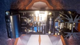
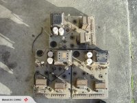
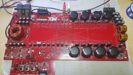
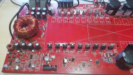
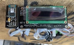
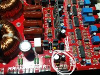
I have a Motu 8A acting as an active crossover which is connected to a Crestron CNAMPX-16X60 amplifier. I'm trying to gain match the output of the Motu to the input of the amplifier.

The Motu, being pro gear, has a balanced out but can work as unbalanced with a floating R from a 1/4 TRS, which I'm using. Measuring the Motu with a scope I see an max output of ~4.5v peak-to-peak (non-clipping).

This is by far too much for the amplifier which needs a significantly smaller signal. So I can configure the Motu to significantly attenuate the signal but I'm assuming that's not doing wonders for the D->A conversion as it'll simply limit the effective bits used.

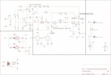
So I want to make a set of line-line attenuators with a best guess of the usual +4dBu -> -10dBV or about 11.79db attenuation which comes down to a K-factor of ~3.88.

From the specs I can see that the amplifier input impedance is 28kohm and the Motu has an output impedance of 100ohm.

Ideally I'd like to take these difference into account but I didn't find the math on how to do that exactly and which topology would be best suited for this. Any tips would be highly appreciated.

What I did find was some help on Uneeda Audio - Build your own attenuator pads where it's recommended for line-line to use a simple L topology making the input impedance leading.

The recommendation there, was to use the input impedance (28kohm) as the series and the shunt would then be ~7k2ohm.

I'm looking for some feedback on if that's the best way to do it, or if there are better ways to solve this.

Thanks!

Boston Acoustics CR85

8 ohm nominal imp Boston Acoustics CR85 has 4 ohm DC resistance?

Does anyone have a pair of Boston CR85 speakers?


CR85 is 8 ohm nominal impedance. But I get a reading of 4.0 ohms DC resistance across the speaker terminals of the CR85 pair that I just got on ebay :sigh:

4.0 ohms DC resistance is notably lower than would typically be seen on an 8 ohm nominal impedance speaker. I don't know if there might be a problem, and would like to know if this is normal for this particular model.

Does anyone have a pair of Boston CR85 that they could measure for DC resistance and report your findings here?

A bit of technique to share in PDF

Hello All,

2 PDF treating:
. Regulator testing
A comparative overview of power supply regulator designs with
listening tests by John Walton

.like Quasimodo
The Link Between The Phase Margin And The Converter Transient Response by
Christophe BASSO

may be interesting for some one

Regards
Ch

Attachments

Low power sound level meter with octave filtering

I've built the following Hackaday project as a starting point, using an ESP32 and MEMS mic:

ESP32-I2S-SLM | Hackaday.io

Next I'd like to augment it by implementing a 1/3 octave filter so that I can calculate a Leq in each band in real time, also exponential time weighting and stats calcs. I haven't tried yet but I'm concerned the processing will be too intense for the hardware and it won't keep up.

My project priorities in order are:
  • Low power (ideally <1W)
  • Ease of development (Arduino-like is nice)

I'm a bit green with MCU/MPUs but I understand ESP32 is general purpose whereas there are DSP optimized devices which can more efficiently perform this type of processing.

Questions:

  • Should I try doing this on ESP32 or is it a waste of time?
  • Is there a platform I should consider replacing the ESP32 with, or a processor I should think about partnering with it to do the DSP heavy lifting?

Quad 22 on-off switch

I am working on replacing the snubber network across the on/off switch on a Quad 22 pre-amp. For those of you who are not familiar with this piece of equipment, the on/off switch on the pre-amp serves as the on/off switch for the power amplifiers as well, connected via an umbilical cable.

When hooked up to a variac set at 15 volts AC from the wall, I am still seeing 15 volts AC through the umbilical cable, on the other side of the switch regardless of whether the switch is on or off. Looking at the schematic more closely, I notice that the snubbers are wired in parallel to the switch.

One the one hand this makes sense; on the other hand, it seems that they would serve as a bypass for the switch altogether, so that even when the switch is off there would still be mains voltage going out through the umbilical cord to the amplifier. This would explain why I'm still seeing voltage, but it would also mean that the on/off switch is effectively useless as it would be permanently bypassed.

Is this correct? Or am I missing something? I want to make sure I have it wired correctly before proceeding.

I've attached an excerpt of the schematic for the switch and the snubber. The full schematic can be seen here:

http://www.keith-snook.info/Schematics/QUAD 22 Schematic.pdf

Attachments

  • q22-switch.jpg
    q22-switch.jpg
    105.6 KB · Views: 200

DML4000a

Hi,
I had a accident and blew my dlm4000a board,
I replaced the irs2013s and the hef40001bg
and a couple of 1n4148.
Now i got signal after the dil4060b
at R19 on my scematic,
and strong signal att Q1 AND Q2.
but i got no signal at R14 and R15.
I reversed engineered this , maybe somewhere theres an error or wrong values.but main thing is there is no audio out.
I got the the right voltages like +VEE18 and so on.
Any one know what to expect out of dli4060 and how the signal get to the hef40001b, I tried to se a connection and measure, but missing something here.
any ides is helpful. 🙂

maybe someone had a replacement board, with other type of chips, when dli4060b is only on aliexpress.......

Attachments

Listening opportunities for LX-521 and CBT-36 in or near to germany?

Hi!

There are two speakers I would be specifically interested to listen to.

1) The LX-521 designed by Siegfried Linkwitz:
LX521 Description

2) The CBT-36 curved line array designed by Don Keele:
CBT 36 Circular Arc Line Array Loudspeaker | Parts Express Project Gallery

Any folks here that own any of these and would like to give me the opportunity to listen to them? I live in southern germany, so anything within Germany, the Netherlands, Belgium, Austria, Italy and the Czech Republic could probably be arranged...


Looking forward to your responses, PM is also welcome!

Cambridge Audio A500 RC static left channel

Hi, So my Cambridge Audio A500 amp has developed some static in left channel and tapping on volume knob often makes it go away for a bit. I have used the amp as just a pre amp and it still does the same thing so I dont belive its in the Amplifier section. I took have cleaned the pot with deox it few times and that hasnt solved it. I took Amp apart to see if possibly bad solder joint on the board where the pot attaches and that looks fine to me. Im at a loss. I was going to jus tse ebaout ordering a new volume pot for it but i cant seem to find correct part. Its made by Seawell for CA and looking for a suitable replacement has been daunting. Anyone have any suggestions?
Projects by fanatics, for fanatics
Get answers and advice for everyone wanting to learn the art of audio.
Join the Community
507,641
Members
7,882,267
Messages

Filter

Forum Statistics

Threads
405,945
Messages
7,882,267
Members
507,641
Latest member
Gousty