Hi all.
I'm building a two way speaker.
in order to do some tests for the box volume and port tuning , i build a test enclosure.
I'm testing different volumes and tuning frequencies.
The drive i use is Dayton Audio DS135-8.
The suggested volume for this drive is ~5 liters.
during measurement of the port i notice unwanted peaks which are very high in db SPL.
They are to low to be port resonance.
I tried 2 port diameters: 35mm and 28.
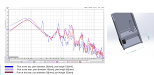
Attached is an image with the test results and enclosure description.
initially i had the port on the top
Port with a length of 53mm and diameter of 28 (this was an initial guess on the ruining frequency.
You can see there are meany peaks.
I then moved the port to the back of the box and the 220Hz beak disappear.
I change to a bigger port, diameter 35mm and a length of 60mm.
no effect on the peaks.
I also increased the box volume to 9 liter instead of 5. no effect.
Can you say what is the source for these peaks? can it be fixed?
Thank you
Ran
I'm building a two way speaker.
in order to do some tests for the box volume and port tuning , i build a test enclosure.
I'm testing different volumes and tuning frequencies.
The drive i use is Dayton Audio DS135-8.
The suggested volume for this drive is ~5 liters.
during measurement of the port i notice unwanted peaks which are very high in db SPL.
They are to low to be port resonance.
I tried 2 port diameters: 35mm and 28.
Attached is an image with the test results and enclosure description.
initially i had the port on the top
Port with a length of 53mm and diameter of 28 (this was an initial guess on the ruining frequency.
You can see there are meany peaks.
I then moved the port to the back of the box and the 220Hz beak disappear.
I change to a bigger port, diameter 35mm and a length of 60mm.
no effect on the peaks.
I also increased the box volume to 9 liter instead of 5. no effect.
Can you say what is the source for these peaks? can it be fixed?
Thank you
Ran
Attachments
I'll start the ball rolling by suggesting that these peaks may be due to internal box resonances that are audible through the port.
Is your box adequately lined with absorbent material at this stage in your testing?
Is your box adequately lined with absorbent material at this stage in your testing?
Hi
I tried adding few different materials, but the effect was very low.
i tried poly fill and it did not have any effect.
I tried Sonic Barrier 3/4" from part express. did not have more than a few pieces so.
it could only cover one side of the box.
it did not have any effect.
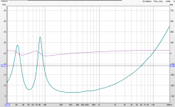
The only thing that did show big improvement is when I put a piece of heavy sponge between the port and the drive. this dumped the the resonances dramatically.
By the way, the impedance measurement does not show any issues.
see attach
I tried adding few different materials, but the effect was very low.
i tried poly fill and it did not have any effect.
I tried Sonic Barrier 3/4" from part express. did not have more than a few pieces so.
it could only cover one side of the box.
it did not have any effect.
The only thing that did show big improvement is when I put a piece of heavy sponge between the port and the drive. this dumped the the resonances dramatically.
By the way, the impedance measurement does not show any issues.
see attach
Attachments
I would be looking at the possibility of reflections at the higher frequencies from the basket and magnet assembly first.
I don't see any internal cabinet measures. You are measuring port resonances, cabinet airborne resonances, nearby objects reflections...
You have mentioned trying polyfill yet you said nothing truly specific about it.
You have mentioned trying polyfill yet you said nothing truly specific about it.
Hi Lojzek
The internal measurement are shown in one of the images i posted.
They are:
Width 150mm
Depth 250mm
High from 150 to 500mm.
At 150 it is about 5 liters.
I tried different volumes but the same effect.
The measurements are near field of the port.
I will add the near field of the drive.
I can do more test with any thing you suggest.
From the replays here i understand that the problem is internal box resonances.
suggested above was to add dumping material on the drive frame.
Did not try it yet.
I did try the Sonic Barrier (from parts express) on the magnet.
It add no effect.
Can you suggest base on the measurement and shape of the box, a damping material and how to apply it?
This is a learning project for me and i'm willing to try anything 🙂
Thanks
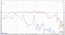
The grouping of resonances between 1 and 2k, and 4k suggest that they are relatively independent in frequency of the three cases you have tried.
I'll start the ball rolling by suggesting that these peaks may be due to internal box resonances that are audible through the port.
Is your box adequately lined with absorbent material at this stage in your testing?
Seconded.
25cm / 50cm = 680hz. That's one peak wrinkled out in the firm of a standing wave, surely.
Vent output is comb filtering with the driver's output, which is normally invisible when Options 'Masked' is active. Sim in HR's wizard and use Chamber/'Path' to watch them alter and as the delay is changed from '0' = vent and driver is radiating from the same point in space due to the vent's WLs being so large to spikes reduced to being above the driver's response, indicating this is the amount of delay required, though as you learned with the sponge, this is the pioneer's way to solve an acoustical problem with an acoustical solution 😉.
GM
GM
GM knows.
@GM, how do you measure such that you account for the path length? I suppose it becomes eradicated when merged with far-field?
@ironsf Can you clarify the box dimensions, please? A 15x25x50cm bx = ~19L. You mention a 5L and 9L box. Which is it or am I being dim?
@GM, how do you measure such that you account for the path length? I suppose it becomes eradicated when merged with far-field?
@ironsf Can you clarify the box dimensions, please? A 15x25x50cm bx = ~19L. You mention a 5L and 9L box. Which is it or am I being dim?
Last edited:
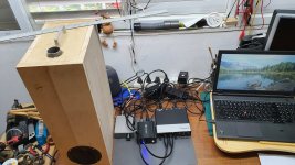
Where your port inlet inside the enclosure is at? If it is near a wall boundary like in the 3D model in your attachment, it might be your problem. If there happens to be a standing wave pressure node at the inlet it likes to go through the port. All standing waves have pressure nodes at the walls at least so thats the worst position for a port inlet to be.
Try move the port inlet to somewhere between 1/2 -1/4 of any dimension to hit some velocity nodes instead (no pressure) and see if it helps.
Cool prototype box!🙂
Ps. damping material has most effect where there is velocity, placing it at walls (pressure) isn't as effective.
Try move the port inlet to somewhere between 1/2 -1/4 of any dimension to hit some velocity nodes instead (no pressure) and see if it helps.
Cool prototype box!🙂
Ps. damping material has most effect where there is velocity, placing it at walls (pressure) isn't as effective.
Last edited:
@GM, how do you measure such that you account for the path length? I suppose it becomes eradicated when merged with far-field?
At the vent. Very far-field due to huge differences in WLs involved.
GM
Where your port inlet inside the enclosure is at?
Ps. damping material has most effect where there is velocity, placing it at walls (pressure) isn't as effective.
Has nothing to do with typical box internal reflections...........
GM
Hi
I'm in this hobby only two years.
I downloaded the Hornresp and stated some Youtube tutorials.
Thanks
I don't see any internal cabinet measures. You are measuring port resonances, cabinet airborne resonances, nearby objects reflections...
- Home
- Loudspeakers
- Multi-Way
- Port unwanted noise/ resonances