Hi
I'm in this hobby only two years.
I downloaded the Hornresp and stated some Youtube tutorials.
Thanks
Greets!
You're welcome!
OK, just noticed you joined in 2014.
GM
🙂 2014
I played and learned a little the hormresp.
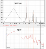
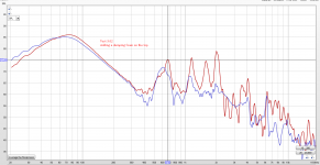
The simulation does show meany problems, and part of them are showed in my measurements.
I start to play with damping material. adding it each time on a different internal face of the box.
Adding it to the top gave a big improvement.
you can see it in the attached file - t3.02 (t3.01 is an empty box).
From here, it didn't mater what i did, i could not dump the 690hz.
according to hornresp it is the back wall. but i could not effect this resonance with the dumping material i have.
I have polyfill, sonic barrier and a very dense mattress foam.
any suggestions ?
Thanks
Ran
I played and learned a little the hormresp.
The simulation does show meany problems, and part of them are showed in my measurements.
I start to play with damping material. adding it each time on a different internal face of the box.
Adding it to the top gave a big improvement.
you can see it in the attached file - t3.02 (t3.01 is an empty box).
From here, it didn't mater what i did, i could not dump the 690hz.
according to hornresp it is the back wall. but i could not effect this resonance with the dumping material i have.
I have polyfill, sonic barrier and a very dense mattress foam.
any suggestions ?
Thanks
Ran
Attachments
The port should be placed in the very vicinity of the speaker, that's all I know 🙂
Hi
what do you mean? in the front near the driver or in the back but on the same axis ?
Thanks!
Well, looking at the various ( thousands and thousands) executions of BR boxes, I'd say both! Plus, the ones that have a downfiring port. This is because the "driver has to feel" what's happening in the box....well, no! Probably "maximising transfer function"? The thing is about resolution, i.e. over a period of time, and in audio a single cycle is looooooong! so the resonating volume of air has to be evacuated as fast as possible...but not too fast because of air velocity in the duct nor not too slow. Indeed I see all the simulations done before building the test box are for finding the correct alignment ( T_S charts for Q of the speaker+box) and for BR to find the correct compromise. But recommendations of putting the duct in the vicinity of the woofer, I see them often. Also using flared ducts changes the fluid motion...
Has nothing to do with typical box internal reflections...........
GM
Hi GM, could you tell more what you mean? Isn't effect of damping material based on dissipating energy from moving air molecules to movement of the damping material? That requires moving air molecules, velocity nodes have the fastest molecules, at pressure nodes the molecules don't move so much = not so effective.
The port inlet location thing doesn't affect internal standing waves, but it seemed the location matters what comes through the port when I did some test a year ago. That could have been my measurement mistake or setup problem as well since I haven't done too much measuring and of course I could have made wrong conclusions. I've got a prototype box with port on a detachable panel and I could flip the panel so that the port is almost bottom of the enclosure or about 1/4 along the longest dimension. Sure enough can't even find the measurements now, hah 🙂 I've been renovating our house for past several months, no time for DIY tinkering..
ironsf, if it is not too difficult move the port inlet to about center of the inside of the box and see if there is difference. If my theory has any ground, the ~680Hz peak should drop dramatically when the port inlet is center of that 25cm dimension (max velocity with the 680Hz wave).
Last edited:
Hi GM, could you tell more what you mean? Isn't effect of damping material based on dissipating energy from moving air molecules to movement of the damping material? That requires moving air molecules, velocity nodes have the fastest molecules, at pressure nodes the molecules don't move so much = not so effective.
The port inlet location thing doesn't affect internal standing waves, but it seemed the location matters what comes through the port when I did some test a year ago. That could have been my measurement mistake or setup problem as well since I haven't done too much measuring and of course I could have made wrong conclusions. I've got a prototype box with port on a detachable panel and I could flip the panel so that the port is almost bottom of the enclosure or about 1/4 along the longest dimension. Sure enough can't even find the measurements now, hah 🙂 I've been renovating our house for past several months, no time for DIY tinkering..
ironsf, if it is not too difficult move the port inlet to about center of the inside of the box and see if there is difference. If my theory has any ground, the ~680Hz peak should drop dramatically when the port inlet is center of that 25cm dimension (max velocity with the 680Hz wave).
Hi
I will try it today!
but as to port length is only 53mm, it will not be in the middle of the 250mm
Thanks
Ran
Masters ?  Brian ? Bjorno ?
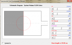
Without going too far, keeping same target response, a box suggestion, simed as OD, with stepped segments. Speaker & damping placement make huge difference, as for TL.
Brian did a nice experimentation with 4th BP speaker placement.
Brian ? Bjorno ? Without going too far, keeping same target response, a box suggestion, simed as OD, with stepped segments. Speaker & damping placement make huge difference, as for TL.
Brian did a nice experimentation with 4th BP speaker placement.
Attachments

Oh I just noticed I've used wrong term, by damping material I was thinking stuffing like polyfill, not bitumen or the like that sone attach to enclosure walls to dampen the enclosure resonances. Sorry aboutthe confusion.
It will take me some time to understand you suggestion 🙂
it's hard for me to understand the 3d picture of the box
it's hard for me to understand the 3d picture of the box
There are two things to damp with a box.
Internal energy flying around, either standing waves or rear cone internal mid energy, reflected around inside, and which can exit from a port. This latter needs careful positioning of the port's internal opening to avoid it as much as possible.
It also can be dissipated to a large extent with the use of internal absorption, eg. BAF wadding, but if you fill the box the fundamental bass reflex resonance will be attenuated, so usually it is placed around the walls to allow a central 'flowing path' for the high air velocity bass frequencies.
A compromise thickness of wadding is required to maximise each, the mid attenuation, and the bass O/P.
The bitumen application is to absorb panel vibration turning it into heat, and does the BAF with the mid energy. I'm sure you know about port diam. and length with regard to 'chuffing'.
Last edited:
Pharos, thats exactly what I was after, thanks for clearer explanation 🙂
Picowallspeaker, why not small box wouldn't have standing waves? Surely standing waves are not frequency limited only to big boxes. Higher frequency sound carries less energy so they are more easily damped though.
Picowallspeaker, why not small box wouldn't have standing waves? Surely standing waves are not frequency limited only to big boxes. Higher frequency sound carries less energy so they are more easily damped though.
Next time you'll see written "standing waves" inside an enclosure you know that the guy needs a little revision of acoustics
Hi GM, could you tell more what you mean? Isn't effect of damping material based on dissipating energy from moving air molecules to movement of the damping material? That requires moving air molecules, velocity nodes have the fastest molecules, at pressure nodes the molecules don't move so much = not so effective.
The port inlet location thing doesn't affect internal standing waves, but it seemed the location matters what comes through the port when I did some test a year ago. That could have been my measurement mistake or setup problem as well since I haven't done too much measuring and of course I could have made wrong conclusions. I've got a prototype box with port on a detachable panel and I could flip the panel so that the port is almost bottom of the enclosure or about 1/4 along the longest dimension. Sure enough can't even find the measurements now, hah 🙂 I've been renovating our house for past several months, no time for DIY tinkering..
Greets!
Lucky you! I've been 'renovating' for a variety of reasons since 2000 and thanks to years of additional storm damage, increasing health issues has me further behind than when I started. 🙁
My remark referred to the vent location in a typical box being irrelevant.
Folks saying there's no standing waves [reflections] in a typical woofer box is incorrect as stated. They are just too small to affect the intended pass band of a LF system.
Folks saying these higher frequency reflections having no bearing on the sub's output is technically incorrect also, but are easily damped as you noted.
A typical vented box is presumed to have a uniform particle density and the vent is a 1/2 WL resonator with a 1/4 WL fundamental [open pipe], so it doesn't let any noise inside the box out, it's too busy modulating [comb filtering] the backside of the cone, but its pipe harmonics does generate its own 'music that comb filters with the driver's output.
Make the box with no parallel walls < 12 degrees slope included [IIRC] and damping can be reduced to [next to] nothing.
The one's in the box is what makes them sound 'hollow', so add damping to 'taste' and if you want to damp the others, then damp the vent to 'taste'.
Then there's the delay between the vent and driver to consider, i.e. what excites the vent on the inside comes out the other side delayed, so the pioneers decreed that the closer the vent to the driver the better, to the point of originally putting the driver in the vent and still holds today in a typical vented alignment, but if we separate them by a labyrinth/high aspect ratio box/tube we can deal with these major pipe harmonics/comb filtering that does impact/limit the speaker' gain BW.
The pioneers typically used a basic reflex vent or very short duct at most due to the driver's specs required at the time, but nowadays [much] longer vents are more the rule than the exception, ditto high aspect ratio ones, hence the results you're getting moving the vent to different sides of the box.
GM
"
Internal energy flying around, either standing waves or rear cone internal mid energy, reflected around inside, and which can exit from a port. This latter needs careful positioning of the port's internal opening to avoid it as much as possible."
Can this be simulated? or trial and error?
Thanks
Are there disadvantage of making the rear wall closer to the mid woofer as possible in order to increase the standing wave frequency above the xo point?
- Home
- Loudspeakers
- Multi-Way
- Port unwanted noise/ resonances