TSEII: all was going well until...

...until I smelled smoke.

This happened three days ago while I was measuring the V1/V2 voltages on pins 3 and 9. The amp is now exhibiting the same symptoms noted in this thread, except that this seemed to occur in both channels simultaneously, and I'm not measuring a short between the drain and source on either MOSFET. Also, R14 and 25 measure their nominal 20K and don't show any obvious signs of overheating.

Some specifics:

  • The CCS ICs for V1 and V2 are apparently fine; I can adjust both to a stable 175 V.
  • V1 and V2 themselves are behaving normally.
  • Adjusting bias pots R12 and R23 has little or no effect on output current.
  • B+ for V3 and V4 is 185 V (measured between ground and plates).
  • V3/V4 current was 167 mA each (!) as measured across R18/R29
So I have several questions:

  • First, I'm fairly certain I've blown the MOSFETs, but why am I not reading a short between pins 1 and 2 (drain and source, if I've read the pinout correctly)?
  • Also, around several of the board's mounting holes I noticed that there is very little clearance between the holes themselves and the adjacent traces. The #6 stainless washers I used in my mounting hardware appeared to be dangerously close to overlapping those traces. Is it possible I've created a short to ground? Do I need to use insulated washers or other hardware?
I've already filled out a shopping cart at Mouser for lots of spare silicon, but I'd just like to know if I've overlooked anything before hitting the "Order" button (I already know better than to ask for a check on my sanity 😀).

I found it odd how the amp continued to produce somewhat decent audio after the magic smoke escaped. There was a noticeable increase in distortion and a drop in output, but I couldn't hear anything else dramatically obvious. But what really amazed me was how those cheap 2A3B's (more like 2A300B's) ate 30 W each without a burp. Not even a hint of red plating during the time it took me to realize what had occurred - which was embarrassingly substantial.

The magnetic components, however, were very unhappy. They told me not to let it happen again.
  • Like
Reactions: wa4htz

Tools for use with SMD hot air gun

I've just bought a cheapo hot air gun, the type with the fan inside the handle. I only need one very occasionally. I can usually get by with my soldering irons.

Anyway, the hot air gun came with various accessories: side cutters, tweezers, screwdriver, etc. and a strange looking 6mm dia x 100mm long rod with whiskers on the end. The whiskers are made of 0.5mm dia spring wire doubled back on itself and screwed to end of the rod.

I have absolutely no idea what it could be used for; anyone here know?

JFET COMPLEMENTARY SYMMETRICAL IPS

I am now studying a complementary symmetrical Jfet IPS to complete my most recent power amp lineup.

Initially I started with a complementary differential Jfet IPS mirror loaded but did not continue due to the difficulties found in avoiding VAS operating point variations due to beta differences and temperature variations.

So now I am using a more typical design without mirrors but in order to increase OLG I placed a Darlington over each input Jfet.

Simulations look very good but I would appreciate input from the experts before I start laying out a pcb.

1 - I am using KSC1845 as the darlington bjt for the positive IPS side that uses K170 jfets. Should I use a higher beta bjt ? What would be the best choice here ?

2 - The same question must be placed regarding the negative LTP where I am using KSA992 and LSJ74 jefts.

3 - For the VAS I chose to use a beta enhanced connection in both sides. Should I contemplate the option of cascoding the VAS instead ?

Hope this design rises enough interest so we can have a good discussion regarding this type of symmetrical amp.

Attachments

Subjective effect of Baker clamps

Over in the Headphone Systems forum, I started a thread describing a couple of discrete amplifiers I designed. The first (HPA1) is a Blameless-style circuit with TPC and very high open-loop gain; the second (HPA2) is based on Bob Cordell's error-correcting MOSFET amp driver, also with TPC.

HPA1 originally used a VAS current limiting transistor. It had severe oscillation on positive clipping, so I removed the limiter and replaced it with a Baker clamp diode, which worked very well on the test bench.

Subjectively, HPA1 mostly sounded good, but there was something wrong in the midrange. This was the impression of my audiophile friend who evaluated the amp. I didn't hear the problem at first, but it was apparent after I built HPA2, which sounded much better to my ears. (My friend has not listened to HPA2 yet.)

I subsequently removed the Baker clamps from HPA1 and my impression is doing so improved the sound. I now find it hard to distinguish the two amps.

I asked in my thread, but I'd like to ask here, if anyone has tried Baker clamps across the VAS and found they degraded the sound. What I heard was a sharpening of the tone, and a loss of ambience, "air," and soundstage. Because the amp uses TPC, the diode junction capacitance is enough to make a big change in the compensation (according to SPICE) across most of the audio band. So the VAS transfer function is heavily dependent on the diode's junction capacitance throughout the midrange.

This whole subjective listening thing is a sticky wicket. Normally, I am skeptical of "golden ear" reports and I don't trust my own listening impressions. But the difference seems real to me.

Understanding Phase Response Graph

Dear diyaudio forum,

I have ended up with the following phase response for a simulation in Hornresp. I do understand the basic idea of how phase works. However, reading this graph, I have no clue how to interpret it.

The most basic questions would be: Is this good or bad? And: What is desirable in a phase response?


Many thanks,
Simon

Attachments

  • Hornresp Phase Response.png
    Hornresp Phase Response.png
    406.5 KB · Views: 197

Non Commercial 2 Way Standmount Speaker Project

Hi all,

Here a free non commercial 2 way standmount speaker project using SB Acoustics driver, SB26ADC-04 tweeter and SB15MFC-08 midwoofer.

I keep the cabinet design as simple as possible, there we use 1" MDF without using brace inside the cabinet. The external dimension is 20x40x30 cm (WxHxD) producing about 12lts internal volume. I add 0.5" round at the side of the baffle.

This is a ported speaker design. I use 2" diameter AW PVC pipe for the port, it internal dimension is 5.3cm, and it length is 23cm (this length include 1cm flare both ends) resulting 41.5Hz box tuning.

I use felt inside upper, bottom, and side panel of the box, also use a little dacron behind the woofer. Resistors are cement resistor 10W rating for the tweeter, and 20W for the woofer. Inductors are air core 18AWG.

Measurement taken at 65 cm, tweeter on axis, 3.084ms gating, non smoothing. Hope you'll like it.


Regards,
Roy

Attachments

  • Speaker.jpg
    Speaker.jpg
    300.2 KB · Views: 370
  • Speaker Box.jpg
    Speaker Box.jpg
    508.2 KB · Views: 382
  • XO.jpg
    XO.jpg
    45.7 KB · Views: 931
  • Simulasi FR.jpg
    Simulasi FR.jpg
    281.6 KB · Views: 383
  • Pengukuran FR.jpg
    Pengukuran FR.jpg
    153.3 KB · Views: 329
  • Pengukuran Impedansi.jpg
    Pengukuran Impedansi.jpg
    272.7 KB · Views: 234

Recommendations 300b SET amp

New to tubes in general but after hearing an (expensive) SET 300b amp I know what I want to get. So looking for DIYers/local artisans who can make me an amp or recommend me a place to get one. I prefer to buy locally in Europe if possible.

There are so many makes out there and it’s so hard to audition that am trying to collect recommendations and tips for finding my happiness...🙂

Have anybody seen any other measurements of Monacor SPH-175HQ than DIBIRAMA's??

Hi,

I am looking for a driver that's I'd exactly like DIBIRAMA's measurements of this driver?? I wonder because DIBIRAMA's measurements of frequency response is VERY different than on Monacor spec sheet, but the funny thing I have been looking for a driver that behaves like DIBIRAMA's measurement for over a year.

All other drivers DIBIRAMA's have measured have been correct and you can see the trend from the spec sheet the manufacturer supply.

So, my problem is that i need to find more measurements supporting DIBIRAMA's results.

Can you guys help me out with this?

The driver is really unusual if DIBIRAMA has got it right, i goes perfectly straight to 1800, thrn a small 2-4dB peak and after that just dies of totally! I mean there's like a 28db/,,oct lowpass at 2500hz.

This is JUST EXACTLY what i need for a driver in one of my project speakers.


Can you help me out? I know it is very popular i Germany but i am only able to read and understand german. Maybe some one german here can post in a german diy forum asking my same question?
Maybe a member on here might have a measurement of it?

Please help

Best wishes JK

I hope you can help me

Mackie SRM1801 Transformer information

Hi,

Does anyone have information on the following transformers?
They are both out of a blown Mackie SRM1801 smps. ATAR 25949 andATAR 0025946.

Any information regarding secondary output voltages would be appreciated. Availability and/or a supplier or suitable alternative would also be appreciated.

Pics are attached.

Thank you.

Attachments

  • E97630F4-9972-433B-8074-854F9F34CC08.jpg
    E97630F4-9972-433B-8074-854F9F34CC08.jpg
    610.1 KB · Views: 135

SVS PC-2000

i,

I need some help to solve my issue with this SVS subwoofer amplifier.
It is a Class-D amplifier 500/1100W.

Issue is that it has no signal on output.
I measure No DC on output, so this is ok.
Measured all other DC voltages are also Ok.
LED goes Blue after turning it ON, also ok.
But when i measure what is coming to PIN.1 on AD converter
my multimeter says 2.4VDC but no (AC)signals here when SIG.generator is turned on AT INPUT.
I need some help to investigate it futher or should i just replace AD converter cause it has DC on pin .1 ?

Thanks for helping.
Also hope it can help others with same issue .

Attachments

  • IMG_redigert2.jpg
    IMG_redigert2.jpg
    897.9 KB · Views: 205
  • IMG_20211107_135355.jpg
    IMG_20211107_135355.jpg
    426.9 KB · Views: 137
  • IMG_20211107_135416.jpg
    IMG_20211107_135416.jpg
    334.2 KB · Views: 122
  • IMG_20211107_135440.jpg
    IMG_20211107_135440.jpg
    587.6 KB · Views: 129
  • IMG_20211107_135453.jpg
    IMG_20211107_135453.jpg
    495.4 KB · Views: 127
  • svs-pc2000.jpg
    svs-pc2000.jpg
    25.4 KB · Views: 108
  • AD_converter.png
    AD_converter.png
    18.1 KB · Views: 121

Replacement Parts for Alps Input Selector of Mission Cyrus II (Rotary Switch)

I am looking for very special replacement parts, which are in use inside in several Alps input selector switches. The naming of this parts I don't know.

This parts are show in the first both images under
Suche Kontaktbrucken /-schieber fur Alps Eingangswahl-/Umschalter in Hessen - Ginsheim-Gustavsburg | Radio & Receiver gebraucht kaufen | eBay Kleinanzeigen

What is the exact name of these parts and where I can order?

Thank you very much for advices.

Mount powertrans TO3 to heatsink

Mount powertrans TO3 to heatsink

Hello!

I have built a JLH class A amplifier (updated vers 2003). Now it is time to put the amp in chassi, Dissipante 4U 300mm from Modushop.biz (modushop.biz/site/index.php?route=product/product&path=207_277_279&product_id=220)

There will be one chassi per channel, ie in total two chassis (Left & Right).

Heatsinks are included in this chassi.

The power transistors MJ15003 is TO-3, in total 2 per channel.

Q: How can I best mount the TO-3 to the heatsinks?

Thanx in advance!

/Fartblind

JBL GTO1201.1

The 10uf 200volt caps are bad in this amp .

I forgot how to do this .

The amp has 4 caps .

Can I use 4 polarized caps on this amp to replace the ones that are defective ?

Like solder one positive in the board hook both negatives together and solder the positive lead from the 2nd cap into the board .

If so what value caps would I need and how many volts?

Attachments

  • D2F2484A-6F77-4FB1-9FAB-D27854769E5E.jpg
    D2F2484A-6F77-4FB1-9FAB-D27854769E5E.jpg
    995.5 KB · Views: 86

12AU7 / 12AX7 push-pull

I'm taking a shot at a mini stereo amp. Per-channel it uses 2 dual triodes to make the PI (12AX7) and output (12AU7) stages. I'm using a cheap $5 PA matching transformer for the output transformer. A couple cheap 12vac transformers will make my power transformer. I'm stepping 120 down to 12 to grab heater power then stepping 12 back up to 120 with the second transformer. A voltage doubler provides me about 300vdc. My output transformer has an 8-ohm secondary and quite a few taps on the primary.

0
62.5
125
250
500
1000
2000
4000
8000

I'll use the 4000 for my center tap and 0 and 8000 for the 2 phases. B+ will be around 225~275v to the 12AU7 and 200v to the PI.

Here's a pic of the single-ended monstrosity I built just to try it. The power stage is a parallel 12AX7 and one side of another 12AX7 for a preamp. No Criticism! I'm still on my learning curve. 😀

I've seen a design like this somewhere online but I can't find it. Anyone have it?

Attachments

  • DSCF2416 (Medium).JPG
    DSCF2416 (Medium).JPG
    161.3 KB · Views: 1,365

2-way hornloaded 130hz->up (12"&1,4")

Hello fellow diy'ers

I'm currently looking intobuilding a pair of fully hornloaded tops to match my ROAR15's, at my disposal I have a pair of Beyma liberty 8 (12E120) and a pair of FaitalPro HF206 converted to HF146 by removing the 2" adaptor housing, mounted on 18-sound XT1464.

Crossover to the ROAR15's will be between 120-150hz, so I'm aiming for a 130hz cutoff on the mid/bass horn for the 12", and I'm also aming to cross over to the 1,4" at around 1kHz, the higher the better, so the question is, is this possible? and what would be the best way to go about it while keeping it diy friendly?

My gut feeling tells me I should avoid any bends in the horn path, and something also feels right about not having a to narrow begining and go for no less than 1/2Sd, 2/3Sd or thereabouts.

Will be used mainly at home but should be able to keep up with the ROAR15's both in character and SPL if possible.

Any spontaneous suggestions?

FS: PEERLESS SLS-P830668 and PEERLESS DX25TG59-04

FS: PEERLESS DX25TG59-04 Tweeters

Hello. For sale a pair of drivers awaiting for a build that will never happen.

PEERLESS SLS-P830668 10" woofers (SOLD) and PEERLESS DX25TG59-04 1" Tweeters pair (AVAILABLE).
They have been used and tested, lets say the would have played like 30 hours, but they are in perfect shape and working conditions unless screws light marks on 10" unit holes, that will always happen.

I want to sell them together in a pack unless complementary offers arrive.

Retail price for 10" subwoofer is 80€ each and for tweeter is 30€ each.

I will sell the pack for 100€ + PP fees if apply + Shipping (10kg total package).

Add a pair of PEERLESS 830657 and you will be able to build Tarkus speaker from Paul Carmody ie:
Paul Carmody's DIY Speaker Pages - Tarkus


FS: Darpa Jr. Speakers (3 Way Bookshelf)

SOLD: Darpa Jr. Speakers (3 Way Bookshelf)

I have too many speakers, branded and DIY, and I cannot listen to them as I should, so it's time to let go one of the most surprising ones: Darpa Jr.

They won the InDIYana 2015 contest at "micro 3 way" category.

DARPA Jr uses an RS180-8 woofer, RS100P-8 mid, and ND25FA tweeter for an all-Dayton design. It’s in a 15 liter (0.5 cu ft) slanted baffle cabinet with a sealed mid-chamber.
THe cabinets has been professionally painted in pearl white metalized colour.

The mid and woofer cross at about 670Hz and the mid and tweeter cross at about 3200Hz. Crossover was made with Jantzen Audio Coils, resistors and MKT caps.

Sound is surprisingily clear, well defined and it surrounds you.
It will play a very nice bass in small rooms and will be deeper in bigger ones.

I can say they have not been played any more than 30 hours for sure. Drivers are not breaking in.

Dimensions (centimeters): 43 H x 21,5 W x 21 D.
Sens around 87dB, impedance 8 Ohm.
Weight 10kg each.

Pictured stands are not included in price, but it could be possible to include them.


Goldmund 27+ diy preamp

Hi would this be any good ?
bought with a job lot on ebay .
i have removed 1 of the 4 2N5566 dual fets and it was very closely matched .
I am currently building a Mezmerize B1 buffer .
would it be worthwhile building this in to a chassis or just stick with the Mezmerize build .
20190621_145946 by glenn jarrett, on Flickr
20190621_150020 by glenn jarrett, on Flickr
20190619_141649 by glenn jarrett, on Flickr

Pinout diagram needed for M-Audio 2496 DB9 connector

Hi all
I have an M-Audio Audiophile 2496 soundcard but do not have the breakout cable that should come with it (I bought it on Ebay). I would like to connect my music keyboard to the card's DB9 connector via midi in/out. I have the DB9 male connector but to make the proper cable I need a pinout diagram of the female DB9 on the card. I have searched the net for many hours and it seems that M-Audio has done an excellent job of keeping their pinouts secret! Does anyone have any tips?
thanks in advance,

Realistic speaker box w diff tweeters??

Was wondering what isn’t too expensive but good enough quality to try with this speakers original crossover and diff tweeters . or do I got to buy passive x overs ?
The original tweeters are misplaced somewhere but weren’t that spectacular anyways and very old .. woofers are new visiton, and sound pretty good .

Attachments

  • A8A6F47F-130E-4E73-AC7D-8C53EB19F3E9.jpeg
    A8A6F47F-130E-4E73-AC7D-8C53EB19F3E9.jpeg
    514.3 KB · Views: 236
  • 538F2D30-C31A-42BE-A2E1-64758127425F.jpeg
    538F2D30-C31A-42BE-A2E1-64758127425F.jpeg
    341.1 KB · Views: 227
  • 64B6891A-6163-430F-ADA3-CC55F817CE97.jpeg
    64B6891A-6163-430F-ADA3-CC55F817CE97.jpeg
    369.6 KB · Views: 209
  • C5924979-EB67-45CD-B8B8-F4493A77A114.jpeg
    C5924979-EB67-45CD-B8B8-F4493A77A114.jpeg
    440.8 KB · Views: 222
  • 2418A5DC-389E-4F6A-A36D-376FDF7039EE.jpeg
    2418A5DC-389E-4F6A-A36D-376FDF7039EE.jpeg
    157.9 KB · Views: 231

Can you help me with my wep page?

I am trying to bring RJM Audio up to the times by activating the https protocol (SSL). My hosting service has done it for me, but although the web pages serve ok none of the images, either inline or linked, load.

I have tried re-uploading the images.
I have checked and all the SRC links are relative i.e. SRC="images/image.png"
I have tried disabling hotlink protection.

Anyone have any ideas?

I am now so very curious about building my own amplifiers.

And have a few questions.

Does it sound as good for much less cash compared to amplifiers one can buy a-la-carte such as Schite, because I'm definitely into the building part of this.

Also what's the difference really in buying off brand drivers for car audio / home audio that aren't a superior brand?

If what I suspect is true I will finally of found peace in the universe. For now. 🙂

Power supplies and DAC misc

Miscellaneous lot of stuff I need to get rid of. Selling as a lot, shipped CONUS only.

$75 shipped CONUS

IMG_1453.jpg
IMG_1452.jpg

5.25 v power supply
9 v teradak ps, no cords
Old working minidsp 2in, 4 out, no cords or supply
9 v toroid (antek)
2x twisted pear placid BP (v2.1.1 and 2.1.2)
TP Opus USB receiver v1.1
2x TP trident v1.1 lightly used

Won’t be able to ship until after next week.

Car Audio Amp - Capacitor

Hi there - one speaker (of 8) in my car audio system is not working. The speaker has been tested independently and works fine. The amp was located under the drivers seat and suffered road salt corrosion, some of which is visible on the PCB. In fact a surface mount capacitor has now fallen off. I think the cap is shot (open circuit when I put the multi-meter on the electrodes, which are almost corroded off). I could unsolder a similar cap and test the value, but I was wondering if there is an alternative "trial and error" approach I could take to validate if this is the source of the problem? I have attached 2 pics - one of the full amp, the second a zoom in on the cap in question (before it fell off, you can see the green corrosion).

Thanks

Attachments

  • amp_1.jpg
    amp_1.jpg
    710.6 KB · Views: 116
  • amp_2.jpg
    amp_2.jpg
    664.7 KB · Views: 113

Questions about electric current and audio circuits.

1) What is electric current?

Electrons flow or electron drift is very slow, to the order of 2.3 x 10^-5 m/s.

According to the Wikipedia article:

"In physics, a drift velocity is the average velocity attained by charged particles, such as electrons, in a material due to an electric field. In general, an electron in a conductor will propagate randomly at the Fermi velocity, resulting in an average velocity of zero. Applying an electric field adds to this random motion a small net flow in one direction; this is the drift."

Drift velocity - Wikipedia

1 Ampere of current is 1 C /s . How many electrons need to flow past a point per second to generate this current? This depends on how many Coulombs are contained in copper wire and what the charge on each electron is.

Number of electrons per second = 1C / (charge of an electron * number of electrons)

The calculation is given in the article. Is this an oversimplification?

Aliexpress vifa dx25tg09

£35.32 5%OFF | 2 Pieces Original Vifa DX25TG09-04/XT25TG30-04 4'' Hifi Home/Car Audio DIY Black Membrane Tweeter Speaker Driver Unit 4ohm/100W
2 Pieces Original Vifa DX25TG09 04/XT25TG30 04 4'' Hifi Home/Car Audio DIY Black Membrane Tweeter Speaker Driver Unit 4ohm/100W|tweeter speaker|speaker pairdome tweeter speaker - AliExpress

I know....I know.....but does anyone care to comment on the provenance if these....anyone bought any?

FS: Quad of Hytron VT-25 triodes NIB

Up for sale a nice quad of Hytron VT-25 triodes from WWII, new in original military packaging. Tested in my TV7-D/U but other than that never used.

More pictures and information available on request, but for that I kindly ask for a WhatsApp or Telegram mobile number to facilitate the communication.

Have plenty of other collectible tubes of US and EU origin.

Price for the quad is 225 EUR or 265 USD, registered shipping included. Payment by PayPal Friends and Family or bank transfer, your choice.

Cheers!

Attachments

  • Hytron VT25 quad.jpg
    Hytron VT25 quad.jpg
    1 MB · Views: 212

Smoking switching power supply transformer

Hello !

I have a car amp whose scheme I can't find Ground Zero GZIA 2230 HPX but we can talk about a similar scheme - gzha-2350x.

This amplifier I suspect has a short or poor insulation in the power supply transformer because it has a very high idle current (6A).
FPQ 50N60 were tested, they had 1.5 V on low - direct polarization, I exchanged them with new ones, as well, high consumption without any load. The load is due to the low insulation of the source transformer.
The amplifier works perfectly fed separately differentially directly on capacitors.
Rectifier diodes are ok. With them removed, there is still a huge idle current consumed by the switching source. FPQ 50N60 is constantly incing.
On electrolytes there is a rectified voltage (the amplifier is powered by 2x12V / 50W in parallel which lights up 75% - so 75 W, so it would be a current of about 6A) but if it is supplied at 12 V directly, the transformer heats up and emits smoke.
I see no other load except the transformer which has a few turns on each winding.
In the primary it has 0.6 ohms.
In the secondary it has 0.2 ohms.
I am interested in who has the expertise on these transformers if the resistors are ok at 0.2 and 0.6 ohm.
It probably needs to be rewound.
I see no other explanation for such a big idle current with impeccable final stage.

Thanks

Attachments

  • service-ground-zero_gzha-2350x_pre_sch_1.jpg
    service-ground-zero_gzha-2350x_pre_sch_1.jpg
    203.2 KB · Views: 99
  • service-ground-zero_gzha-2350x_pre_sch_2.jpg
    service-ground-zero_gzha-2350x_pre_sch_2.jpg
    188.2 KB · Views: 99
  • service-ground-zero_gzha-2350x_pre_sch_3.jpg
    service-ground-zero_gzha-2350x_pre_sch_3.jpg
    255.7 KB · Views: 99

A professional 10" Bass Driver with lowest fres: McCauley's 6222; who have heard ?

A professional 10" Bass Driver with lowest fres: McCauley's 6222; who have heard ?

About
McCauley.com : Products: Components > 6222: Overview
and
McCauley.com : 6222 Specifications
there are the short form data of this in Europe hard to find model.
The high Qms value (nearly 8) are untypicall fur rubber suspension.
This transducer looks very promising, both for three-way solutions and for small subwoofer systems.
Probably this model is most of any home-audio and car stereo speakers vastly superior.

Who have heard them and in which commercial loudspeakers are this transducer in use and in which magazines like
http://www.hobbyhifi.de/Aktuell/Aktuelle_Ausgabe/aktuelle_ausgabe.html
or
http://www.audioxpress.com/magsdirx/voxcoil/index.htm
are to find test reports ??

The Intellectual People Podcast - Clayton Shaw (Spatial Audio Lab)

As a young 12 year old, Clayton Shaw enjoyed building speakers. He always knew what he was looking for, however, reaching the goal took many years and life experiences to achieve his goal. Now at 64, in his opinion after 52 years has reached the pinnacle in open baffle speaker design. Take a listen to Clayton's journey as he navigates through the speaker building business.

Clayton Shaw of Spatial Audio | Ep 43 - YouTube

Attachments

  • 1.jpg
    1.jpg
    523.5 KB · Views: 142

Anyone used this "optical MOSFET relay" ?

I don't have much experience of MOSFETs or any silicon components really, but I stumbled across this which looks useful.

ASSR-4118-003E BROADCOM LIMITED, MOSFET Relay, 400 V, 100 mA, 35 ohm, SPST-NO | Farnell element14

It takes a 3mA current on the input to light up an LED which then switches on a power rail up to 400V.

Anyone used this or similar ?

Seeking help from crossover experts (adding midbass module)

Ok, here goes.

Basically I want to add more bass without adding an active crossover.

So I was to run a “midbass module” with (running in parallel) what I currently have (both would be ported at same freq too).

So question is, if the speaker already has an 18db crossover (say at 1.2khz) to the tweet, can I run a bass module (in parallel) but also with an 18db at a lower frequency (say 200hz) ?

Based on phase and all that, it would have better blending ?

FE208e∑ enclosure?

im thinking about putting together a pair of speakers using fostex FE208EZ sigma.
but i keep reading here they only work in backloaded horn configurations?
actually i prefer a "compact" version in my small room. are these drivers useless in a box bassreflex design?
also i have no experience building cases. so id like to keep it four-by-four.

i see "omage speakers" sell a standmount bassreflex with the 206 driver. is it completely different with 208?

thanks!

Is it okay to put round port sideways of the speaker ? ?

Hello,

I am struggling placing my port, because the enclosure will have an angle at the bottom and therefore I'm losing some precious length there (port is quite long - 35cm). I was planning to put the port sideways of the woofer but realized maybe its not ideal ? I really cannot make a full squared box and I want the speaker to face the bottom of the trunk.

Image attached (got rotated 90° when uploaded...)

Thanks !

Attachments

  • 1636139131037.jpg
    1636139131037.jpg
    354 KB · Views: 147

A good unbalancer suggestion?

Hi there,

I am looking for a differential to SE building block, to be used inside a frequency synthesizer.

This is a bare bone example of such an archetypal circuit:

attachment.php


It should have a good linearity (preferably better than 1ppm), a moderately wideband (1MHz), but it should retain its performances flat for the whole frequency range, and in particular have good IMD performance, even for frequencies above its range.

And it should be reasonably simple of course: it is always possible to solve that kind of problem by throwing lots of transistors at it, but I don't need the luminaries of DIYaudio to do that.

A possibility is to use a Xquad variant, as in the input stage of the Tringlinator, but raw performances and bandwidth are borderline for this application.
Edmond Stuart has nice topologies that could be adapted for my purpose, but they are complex, because they are intended to be used in a FB context, with compensations, and this complicates matters uselessly for me.

Any better ideas?

Attachments

  • Unbal.png
    Unbal.png
    11.9 KB · Views: 563

Speaker builder estate sale

PICTURES HERE: LOTSO SPEAKER STUFF - Google Drive
Location: Seattle, WA

I recently purchased a bunch of speakers / drivers and speaker building parts from the estate of a local speaker builder. I intended to pickup where he left off and build some cool speakers myself during all the COVID downtime, but it turns out I'm way more busy than I thought I'd be....so it's time to pass this opportunity on to someone else. This seems like the best place to do that.

There's way too much stuff to list individually. Most of the drivers are older, sorta vintagey stuff, some older Scanspeak, Coles, Polydax, etc. and some really cool and rare gems. There's just WAY too much stuff to list, and if I was going to bother taking the time to inventory everything, I might as well go one step further and list it all for sale and make way more $. I just don't have time. Maybe you do? Or maybe you'd like to use these for projects?

I'm thinking the best way to sell stuff is by category and just take some offers. No reasonable offers will be refused. I'm just trying to clear out some cabinet space and hook someone up who can put all this stuff to good use!
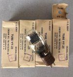
NOS Drivers:

These are NOS drivers in boxes, never opened. There's an insane amount of them.

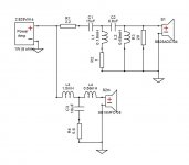
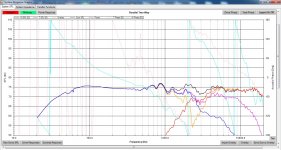
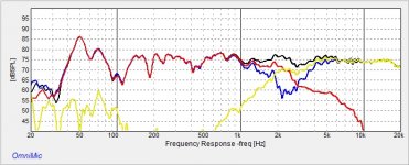
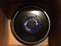
15 cases and 4 individual boxes, or 94 total of the YD180-8P01 low/mid drivers. Don't let the Chinese branding fool you, these appear to be very high quality drivers. The magnets are huge with cast (not stamped) housings, and they are HEAVY for their size. The only info I can find about them online is the following:

Model: YD180-8P01
Impedance: 8 ohms
Rated Power: 60 watts
Freq Range: 50hz-6000hz
Sensitivity: 89±
Q: 0.52
Cabinet Volume: 18 liters
Effective Vibration Radius: 65mm
Vibration Quality (?): 11.4

Apparently these were made by "South Whale". The only speakers I can find that utilize these drivers (or at least nearly identical South Whale 6.5's) are here: Xy-020 6.5 Inch Hifi Speaker Vifa Dx25+south Whale King Mid Bass 8ohm 30-120w 87db - Buy Full Range Speakers,6.5 Inch,Bookshelf Speaker Product on Alibaba.com

Here's a thread on HifiDIY with some info about the drivers specifically (you'll need to translate from Chinese): HIFIDIY- - Powered by Discuz!

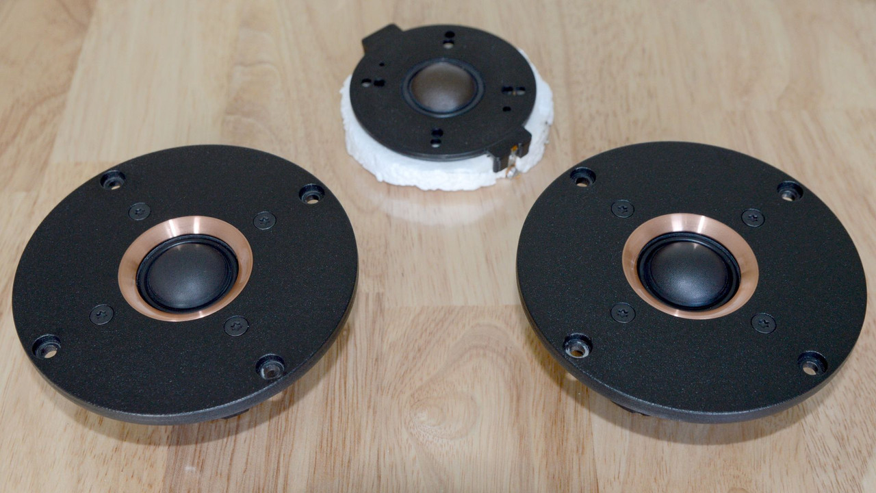
As for the HF drivers in the boxes, I can't really find any info about them, but they are clearly meant to pair with the LF drivers, and even look similar to the Vifa tweeter in the Alibaba speaker. The model # on these is DT516-FS.

There are 5 cases of tweeters, and 10 individuals, or 100 total drivers.

So you'd have enough drivers here to make at least 94 speakers, with a few extra tweeters left over. *EDIT: I think I'm going to keep a pair to install in the cabs I have. So possible minus 2 from this list.

I have no idea what to ask for these, so make an offer? Keep in mind these are very heavy, so shipping will be a factor. Local pickup around Seattle would probably be easiest.

PICTURES: LOTSO SPEAKER STUFF - Google Drive

Other misc drivers

There are several boxes/bins of misc drivers, some loose, some in boxes. This is where you'll find some oldschool Scanspeak, Seas, Coles, Vifa, Polydax, McFarlow, Visonik, Intervox, etc. There are some Chinese ribbon tweeters that look pretty cool and lots of unbranded drivers. I've tried to keep the cones protected as much as possible, so for being in a big pile, they're actually in pretty decent shape for the most part (I had to toss some that were obviously toast). There's no way I'm testing all of these, so it's a crap shoot. I can't really guarantee condition on any of this stuff, but especially the loose speakers. I'm guessing most of them work just fine, especially the ones still in their original boxes, but I'm sure there are some dead ones as well.

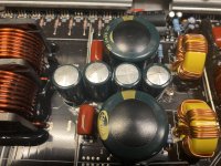
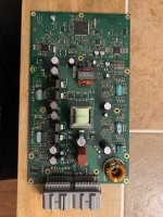
Capacitors, resistors, misc.

There are a ton of caps and resistors. Resistors are of the large ceramic variety. There is a huge bag of 4ohm resistors, and some misc 2ohms too. There are a ton of 10uf 50v caps, one bag of 2uf 200v, a bag of 6uf 50v, and some large white caps that aren't obviously labelled but measure 20uF bipolar on a calibrated Fluke 87V. I have no idea of how much of each there are, just A LOT. There is also a bag of some kind of connector I'm not familiar with, and a bag of misc components.

PICTURES: LOTSO SPEAKER STUFF - Google Drive


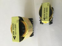
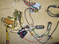
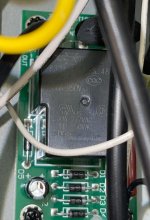
Xformer/inductor stuff

This could probably go along with the above lot for making crossovers, but it's kind of a seperate category, so here goes. There is a giant, and I mean GIANT box of transformer housings or layers (not sure what they're technically called). This box probably weighs about 100 pounds. Shipping would not be fun....but if you really like making your own transformers, it might be worth it. Again, local pickup in Seattle is probably going to be way easier. This "lot" could also include a bunch of misc transformer/inductor wire in different gauges (see pics).

PICTURES: LOTSO SPEAKER STUFF - Google Drive

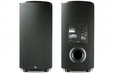
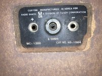
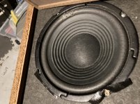
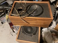
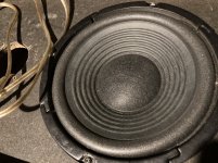
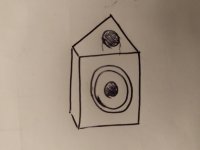
Speaker cabinets and grills:

Probably not worth messing with...I'll probably just throw these in with any of the above groups if someone wants them.

There are too many photos to upload here, so they can be viewed in this Google Drive folder. If anyone is interested in any of these items, or the entire lot, shoot me an offer! Thanks!

LOTSO SPEAKER STUFF - Google Drive

Lowest Noise JFETs?

With Toshiba 2SJ74 and 2SK170 getting harder to find, are there any easily obtainable lower-noise JFET amplifier parts being made today? I know about Linear Systems but they're also spotty to get and expensive. Anything else out there that may not be as quiet as the Toshiba's but offer similar performance in most other parameters (capacitance, etc.) and not so expensive? Thanks.

  • Poll Poll
Current-drive by a valve amplifier

What do you think about the SEP current-drive idea?

  • Brilliant idea

    Votes: 5 17.9%
  • May be good but not exactly this way

    Votes: 7 25.0%
  • Bad idea

    Votes: 7 25.0%
  • I don't know / no opinion

    Votes: 9 32.1%

This is mostly speculation since I have not built this.

Due to less distortion, current-drive would be already widespread if the bass resonance of a conventional speaker did not spoil that. However, solving the resonance issue may bring the current-drive to markets. This probably means some kind of an aperiodic loudspeaker, and there are many possible aperiodic speaker designs. But I won't get into details. Instead of explaining reasons leading to current-drive, I concentrate in the amplifier. I started thinking, how would one design a current-drive valve amplifier.

I approach the idea with a drawing. I borrowed some graphics from W. G. Morley.

(a) A voltage feedback circuit is a good starting point. The feedback may be brought to the cathode of the output valve, a pentode in this case. Resistors R1 and R2 are there for feedback only.

(b) A pentode left without feedback is actually a kind of transconductance amplifier, but not very good one due to distortion. Otherwise it is nice and simple.

(c) A resistor is required for current feedback, so it must be series connected with the load. The amount of feedback may be adjusted by choosing the resistor.

Attachments

  • valve_current-drive.png
    valve_current-drive.png
    147.6 KB · Views: 1,287

Why the difference after driver stage ?

I am looking at the Accuphase P-7100 and A-65 schematic and notice something of interest which I felt I wanted to ask about.

I have attached some pictures down bellow for your convenience. Looking at the attached picture with the schematic section of the P-7100 and A-65, I want you to look at the driver section of both schematics.
We are looking at positive voltage side only. I want you to pay attention to the constant current driver of the P-7100: Q28 2SC4793 driver to Q34 2SC5354 which is a power BJT. If you then look at the A-65,
here they cascade two 2SC4793 drivers. Since I don't have the P-7300 schematic, I had to use the available pictures to see if I could determine how many driver pairs the P-7300 use.

The P-7100 uses 1 driver pair + power BJT on the constant current section and 11 paralleled power BJT's.
The P-7300 uses 2 drive pairs and 10 paralleled power BJTs
The A-65 uses 2 drivers pairs and 10 paralleled power FET's
The A-70 uses 2 driver pairs and ...
The A-75 uses 2 driver pairs and ...

(1 driver pair consist of 1 pcs 2SC4793 (NPN) and 1 pcs 2SA1837 (PNP).

Amp release date:
A-65: 2009-2014
A-70: 2015-2019
A-75: 2019-

P-7100: 2006-2014
P-7300: 2015-

From my perspective, it looks like 2008/09 when the A-65 was released, that they did an overhaul or upgrade on the constant current section which was then used moving forward.

Wouldn't it be possible to adapt this newer 2 driver pairs on P-7100 and give it an upgrade ?


(If you want to see the whole schematic, you have to locate this on your own since sharing official schematics on diya.com that is not pre-approved is frowned upon)

Attachments

  • Why the difference.png
    Why the difference.png
    145.6 KB · Views: 140
  • Accuphase A-65.jpg
    Accuphase A-65.jpg
    179.2 KB · Views: 135
  • a-70-accuphase-4b.jpg
    a-70-accuphase-4b.jpg
    468.3 KB · Views: 116
  • a-75_power_amp_unit.tiff.jpg
    a-75_power_amp_unit.tiff.jpg
    528.3 KB · Views: 116
  • P-7100.jpg
    P-7100.jpg
    280 KB · Views: 115
  • p-7300_power_amp_1.tif.jpg
    p-7300_power_amp_1.tif.jpg
    962 KB · Views: 74

Buzzing sound from power conditioner

Greetings!

This is my first post on diyaudio, so first please pardon if I've made it in the wrong category. Second, while I know a little about electronics, I'm unfortunately far from the target audience of this site—however, I'm hopeful that I could be pointed in the right direction.

I recently acquired a Furman IT Reference 20i power conditioner and noticed a buzzing sound coming from within. Though it's also an isolation transformer, there's no hum, and I've traced the source of the buzzing sound to a small PCB that appears to be a voltage regulator. I've reached out to Furman but their approach is to just return the unit to the shop and get a new one... which seems overkill and unnecessarily expensive (unit weighs in at about 90 lbs).

Any suggestions on what might cause the buzzing and how to address? I'd think it's from that black box at the top of the diodes. I'm comfortable with a multimeter and soldering iron, but not with actual circuit design and troubleshooting.

Unit works perfectly fine otherwise.

Many thanks in advance!

Cheers,
Nick

Attachments

  • 1.jpg
    1.jpg
    700.9 KB · Views: 381
  • 3.jpg
    3.jpg
    424.7 KB · Views: 302

Swap cdm 1 for cdm 0 in Philips CD 204

Hello guys, i have a very worn Philips CD 204, the machine has been heavily used, and the CDM 1 transport is very weak. I recapped the whole machine, but even after recap the machine will not play all CDs, and when i change tracks it always fails to change track and the CDM1 stops reading.

Ive read on the forums that this is due to a worn bearing on the CDM and there is not much that can be done.

I have a donor CDM 0 but i dont know what modifications are required for the CDM 0 to work propperly on the CD 204.

I know that some CD 204 came with CDM 0 so it should be possible.

3 way crossover suggestion for Infinity ServoStatik

It sounds to me like the crossover on my ServoStatik system is having some issues. The high and/or mid channels are "bleeding" the left and right signals back and forth. I believe the crossover points are 100 & 2000 hz.

I would love to find an inexpensive crossover that I can use to prove this. Presumably I would need to run it for awhile until I can get the Infinity unit to the shop. Even an auto version would be acceptable - maybe even better since it would be easier to hide.

Does anyone have a good recommendation for a 3 way crossover? A unit that can handle both channels would be ideal, but single 3 way is fine if it's not too expensive... I can just buy two of them.

Thanks!
Mark

Pass Korg B1

I have 2 Korg NuTube B1 for sale. They both need a bit of attention as in adjusting the pots on the PCB. As you can see I tried one with a separate power supply (not included), the original power supply is included. One has J113 and the other 2SK170 (if I remember correct)

I will sell one for € 80 or both for € 140,- excl. P&P. Will ship worldwide.

Attachments

  • NuTube B1_DxO.jpg
    NuTube B1_DxO.jpg
    478.5 KB · Views: 556

PI/FI with Rasberry/Pi

Hello
greetings i am a newbie in the world of dac players i assembled a
rasberry Pi dac player with a cheap pi/fi dac card it works supply
is a 5 volt linear power supply L Adaptor software is volumio.
I want to add this waveshare 5 inch touch screen can anyone help
me with instructions please.
warm regards
Andrew😕

Attachments

  • 186510012_299360908393813_2559430053599369007_n.jpg
    186510012_299360908393813_2559430053599369007_n.jpg
    132.1 KB · Views: 647
  • config.txt
    config.txt
    114 bytes · Views: 85

Hello from Bengaluru, India

Hi,

This is Raghu from Bengaluru, India. Software Engineer by profession and interested in audio gear and music.
I am planning to build a Soekris DAC with the help of a friend.
Also need to re-host an older AKSA amp into a new chassis.
Will reach out to the forum when the fun begins 😀

The intent is to get this chain working in a few months from now.
Allo Digione --> Soekris DAM 1021 based DAC --> Lyrita Audio DHT tube pre --> AKSA 55 power amp --> KEF R300

Cheers,
Raghu

Is SA9302L Any Good?

Hello everyone. I just found this chip, SA9302L in Savi-tech's website. It could support up to 384k/32bit and DSD256. This chip only sells 30RMB (4.4$) on taobao, which is very competitive to the SA9227 (80RMB/12$) or XU208 (50RMB/7$). I can't find the datasheet yet and I don't know if it's need to be programmed. Seems there are some USB-C to 3.5mm wire are using this chip.
Is there anyone have used this chip on non-portable application?
Projects by fanatics, for fanatics
Get answers and advice for everyone wanting to learn the art of audio.
Join the Community
507,758
Members
7,887,127
Messages

Filter

Forum Statistics

Threads
406,169
Messages
7,887,127
Members
507,758
Latest member
Cindy